Note: Descriptions are shown in the official language in which they were submitted.
CA 02359847 2001-07-20
WO 00/45385 PCT/US00/01659
FLIPPER MECHANISM FOR DOUBLE-SIDED MEDIA
BACKGROUND OF THE INVENTION
This application is a continuation-in-part of co-pending Serial No.
08/744,107, filed
November 5, 1996.
Storage media library systems (jukeboxes) are devices which contain multiple
storage
media drives and many pieces of storage media to accommodate installations
requiring access
to large numbers of storage media, such as optical discs, compact discs and
tape cartridges.
The storage media may be housed in magazines which contain a fixed number of
storage
media. Existing storage media library systems are configured to contain a
fixed number of
magazines and a fixed number of drives.
Typically, a customer will make a purchase decision based on drive or media
capacity. If a jukebox will only handle a maximum number of drives or media,
and still not
meet the customer requirements, then a larger jukebox is required. Some
customers will
require a larger ratio of drives to media and some will require the opposite.
This may
demand the selection of a jukebox which is much larger than needed in order to
fulfill the
specific needs of the customer.
There is a need for a data media storage library with a fixed number of
homogeneous
'slots' which can be populated with either drives or storage media. This
allows for
customization of a library system which meets the specific requirements of the
end user. The
customer can opt to swap drives for media to tailor the jukebox to their
needs, and minimize
the necessity to purchase a larger system with capabilities they may not fully
realize. This
allows for easy future expansion if needed.
SUMMARY OF THE INVENTION
A data media storage library for storing and accessing storage media such as
optical
discs, CDs, tape cartridges, and PCMCIA cards, consisting of a housing
containing a storage
array with a number of storage locations therein; a number of media storage
elements for
CA 02359847 2001-07-20
WO 00/45385 PCT/US00/01659
-2 -
holding the storage media; a number of data transfer elements for reading and
writing
information on the storage media; and a media transport element for moving the
storage
media between the media storage elements and the data transfer elements. Each
storage
location may engage one of the media storage elements and data transfer
elements, thereby
allowing the interchangeability of media storage elements with data transfer
elements within
the storage array. A second embodiment includes a flipper mechanism for dual-
sided media
which can be mounted at one or more of the storage locations and rotate to
flip the storage
media to its other side.
A principal object and advantage of the present invention is that it provides
a data
media storage library with a fixed number of homogeneous 'slots' which can be
populated
with either drives or storage media. This allows for customization of a
library system which
meets the specific requirements of the end user. The customer can opt to swap
drives for
media to tailor the jukebox to their needs, and minimize the necessity to
purchase a larger
system with capabilities they may not fully realize. This allows for easy
future expansion if
needed.
A second principal object and advantage of the present invention is that it
allows for a
drive to be removed from the data storage library while power is on, that is,
it allows the
drive to be "hot swapped", which is now a serviceability requirement in the
industry.
Another object and advantage of the present invention is that it provides a
drive
assembly which contains a quick release fastening mechanism to simplify the
installation and
removal of drives. Installation of drives is achieved by simply pushing the
assembly into a
slot until the spring-loaded latch engages. Actuation of the latch mechanism
is all that is
required to disengage a drive from the jukebox.
A feature of the invention is that the media storage element and the data
transfer
element both have the same width and height, so that a given slot can hold
either one.
Another object and advantage of the present invention is that includes a
flipper
mechanism that can be mounted at one of the storage locations that can be used
to flip the
CA 02359847 2001-07-20
WO 00/45385 PCT/US00/01659
-3 -
storage media to its other side for reading. The flipper mechanism can be
added as a
replaceable part at one of the storage locations and provide dual sided media
access without
modifying any other components of the data media storage library.
BRIEF DESCRIPTION OF THE DRAWINGS
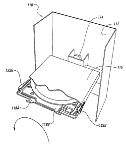
Fig. 1 is a front perspective view of the present invention.
Fig. 2 is a rear perspective view of the present invention.
Fig. 3 is a detailed perspective view of the present invention.
Fig. 4 is a detailed view of the data transfer element adapter.
Fig. 5 is a front perspective view of a second embodiment of the present
invention.
Fig. 6 is a rear perspective view of a second embodiment of the present
invention.
Fig. 7 is a perspective view of the flipper mechanism of the second embodiment
of the
present invention with an empty upper media tray and a lover media tray
holding a compact
disc.
Fig. 8 is a perspective view of a media transport element with a media tray
loaded
therein.
Fig. 9 shows a media tray 118A being inserted into the flipper mechanism of
the
second embodiment of the present invention below the empty tray 118B. The
upper support
finger 122B on the right side of the Figure has been cut away to show the
lower tray support
finger 122A supporting the upper tray.
Fig. 10 shows rotation of the flipper mechanism of the second embodiment of
the
present invention to flip the media to the other side.
CA 02359847 2001-07-20
WO 00/45385 PCT/US00/01659
-4 -
Fig. 11 shows a media tray 118A being withdrawn from the flipper mechanism of
the
second embodiment of the present invention. . The upper support finger 122B on
the right
side of the Figure has been cut away to show the lower tray support finger
122A supporting
the upper tray.
DETAILED DESCRIPTION OF THE PREFERRED EMBODIMENTS
The data storage library of the present invention is generally shown in the
figures as
reference numeral 10.
The data storage library 10 consists of a housing 20 which provides a
protective
environment for the other components of the data storage library 10.
Within the housing 20 is at least one storage array 30 which holds a number of
other
components in storage locations 31. Preferably, more than one storage array 30
is contained
within the housing 20. In the preferred embodiment, the storage array 30 is a
vertical
column, but any other orientation or shape such as horizontal or polygonal is
also possible.
Arranged within the storage array 30 is at least one and preferably several
media
storage elements 40. The media storage elements 40 hold the storage media when
the storage
media are not being read or written to. The storage media can be any media
which can be
used to record information, such as data and graphics. The recording means may
be
magnetic, optical, or any other equivalent recording means known in the
storage media art.
Preferably, the storage media are compact discs (CDs). Preferably, the media
storage
elements 40 are trays which hold the CDs.
Also arranged within the storage array 30 is at least one and preferably
several data
transfer elements 50, which are used to read and write information on the
storage media.
Preferably, the data transfer elements 50 are compact disc drives (CD drives)
but the data
transfer elements 50 may be any equivalent device such as an optical disc
drive, a cassette
drive, floppy disc drive or hard drive. The latest CD drives allow the CD to
be written to as
CA 02359847 2001-07-20
WO 00/45385 PCT/US00/01659
-5 -
well as read from, in which case the media is called a PH. Such writable PDs
are readily
available, an example being the Panasonic LM-RP6500A PD.
A media transport element 70 is movable within the housing 20 to move the
storage
media among media storage elements 40 and data transfer elements 50 within a
storage array
30, and also to move between storage arrays 30 when there is more than one
storage array.
The data media storage library 10 may preferably include a store guide 32
within the
storage array, the store guide 32 having slots 34. In the preferred
embodiment, the store
guide 32 is a pair of plastic molded rails attached to the storage array 30.
The slots 34 act as
storage locations 31.
Preferably, the data media storage library 10 also comprises a number of media
storage element adapter 42 which engage the store guide slots 34 and the media
storage
elements 40 to hold the media storage elements 40 in the slots 34 and allow
the media storage
elements 40 to be removed from the slots 34.
In the preferred embodiment, the media storage elements 40 are magazines 44
having
a plurality of trays therein for holding compact discs (CDs).
Preferably, the data media storage library 10 also comprises a number of data
transfer
element adapters 52 which engage the store guide slots 34 and the data
transfer elements 50
to hold the data transfer elements 50 in the slots 34 and allow the data
transfer elements 50 to
be removed from the slots 34.
In the preferred embodiment, the data transfer elements SO are CD drives 54
and the
data transfer element adapter further comprises a mounting plate 56 and
latching mechanism
57, the latching mechanism 57 engaging the CD drive 54 and holding the CD
drive 54 within
the data transfer element adapter 52. Preferably, the latch mechanism 57 is
spring-loaded.
To meet serviceability requirements, it is preferred that the data transfer
elements 50
can be removed from the slots 34 while power is supplied to the library 10.
CA 02359847 2001-07-20
WO 00/45385 PCT/US00/01659
-6 -
Preferably, the width of the media storage element 40 is substantially the
same as the
width of the data transfer element 50, and the height of the media storage
element 40 is
substantially the same as the height of the data transfer element 50, thereby
allowing the
interchangeability of media storage elements 40 and data transfer elements 50
in any given
slot.
In operation, the user populates the slots 34 with the appropriate number of
media
storage elements 40 and data transfer elements 50 as needed by his
application. When power
is applied, the data media storage library 10 will determine, by appropriate
means, whether a
given slot is empty, contains a media storage element 40, or contains a data
transfer element
50. Appropriate software executing in the data media storage library 10
determines which
data transfer element 50 is to be used or read or write to any given medium in
a media storage
element 40. The media transport element 70 will then move the medium between
the
appropriate media storage element 40 and data transfer element 50.
If the user wishes to remove a media storage element 40 or data transfer
element 50,
an appropriate software command is issued to the data media transfer library
10, the housing
20 is opened, and the media storage element 40 or data transfer element 50 is
removed from a
slot 34. In the case of the data transfer element 50, removal maybe
advantageously executed
by releasing the latching mechanism 57.
A second embodiment of the present invention is shown in Figures 5-11.
A flipper mechanism 110 comprises a flipper chassis 112 which is adapted to be
mounted at one or more of the storage locations 31. A flipper motor 114 is
mounted on the
flipper chassis.
A flipper cartridge 116 is connected to the flipper motor 114 and is
rotationally driven
by the flipper motor 114.
CA 02359847 2001-07-20
WO 00/45385 PCT/iJS00/01659
_7 _
The flipper cartridge 116 comprises at least two storage media trays 118A,
118B
contiguous to one another. One of the trays 118A, 118B holds a storage medium,
such as a
dual-sided compact disc (CD). The compact disc sits in a well or depression
119 in the tray.
When two trays are present in the cartridge 116, the lower tray supports its
media directly in
the well or depression 119, while the upper tray is inverted with the back
surface 119A of the
well or depression 119 upwards.
Although not shown in the Figures, it will be clear that additional flipper
cartridges
116 may be ganged together so that they are simultaneously rotated by the
flipper motor 114.
The flipper cartridge 116 also preferably comprises a tray support member 120
which
is adapted to support the upper media tray 118B within the flipper cartridge
116 when the
lower media tray 118A is removed from the flipper cartridge by the media
transport element.
The tray support member can have any appropriate shape, but in the preferred
embodiment it
is a tray support finger 122 having an elongate shape with a support tab 124
at one end. The
tray support member 120 is pivotally mounted in the flipper cartridge 116 so
that the tray
support member 120 is deflected by the media tray 118A as the tray 118A enters
the flipper
cartridge 116 below the media tray 118B.
The flipper cartridge also preferably comprises a tray detent 126 which is
adapted to
retain the media trays 118A, 118B within the flipper cartridge 116 during
rotation.
Preferably, the support tab 124 of the support finger 122 acts as the detent,
engaging the
notch of each tray.
Operation of the flipper mechanism 110 is as follows.
First, the media transport element 70 receives a media tray 118A from either
the
media storage elements 40 or the data transfer elements 50. Figure 8 shows the
media tray
118A after it has been received into the media transport element 70.
In order to flip the medium to its other side, the media transport element 70
is then
positioned adjacent the flipper mechanism 110 The media transport element 70
then inserts
CA 02359847 2001-07-20
WO 00/45385 PCT/US00/01659
_g _
the media tray 118A into the flipper cartridge 116 below the upper tray 118B,
which will be
empty. As shown in Fig. 9, the upper tray 118B will be supported by one of the
lower
support fingers 122A and one of the upper support fingers i22B will be
engaging the notch of
the upper tray 118B while the other upper support finger 122B is deflected (in
Fig. 9, one
upper support finger has been cut away to show the lower support finger).
As the lower media tray 118A enters the flipper cartridge, the lower tray
support
fingers 122A are deflected out of the way by the tray 118A, with one of the
lower tray
support forgers 122A engaging the notch of the lower tray 118A.
The flipper motor 114 is then activated, causing the flipper cartridge to
rotate 180
degrees as shown by the arrow in Fig. 10. During rotation, the medium drops
into the other,
empty media tray 118B, with its other side presented for data transfer. Media
tray 118B then
becomes media tray 118A.
As shown in Fig. 1 l, the lower media tray 118A is then removed from the
flipper
cartridge by the media transport element 70 for presentation to one of the
data transfer
elements 50 for accessing the other side of the medium. As the tray 118A
leaves the flipper
cartridge 116, the lower tray support fingers 122A deflect back into the
flipper cartridge 116
to support the upper media tray 118B.
It will be clear that operation of the flipper mechanism 110 can now continue
when
another media tray is inserted into the flipper cartridge 116 below upper
media tray 118B,
which is now empty.
The present invention maybe embodied in other specific forms without departing
from the spirit or essential attributes thereof, and it is therefore desired
that the present
embodiment be considered in all respects as illustrative and not restrictive,
reference being
made to the appended claims rather than to the foregoing description to
indicate the scope of
the invention.