Note: Descriptions are shown in the official language in which they were submitted.
CA 02359929 2001-07-24
WO 00/47099 PCT/US99/14698
A VANELESS IMPELLER HOUSING FOR A VACUUM CLEANER
Field of the Invention
The present invention relates generally to vacuum cleaners and more
particularly to a vaneless impeller housing for a vacuum cleaner that
increases
operating efficiency and reduces noise attributable to air flow.
Background of the Invention
Efficient and quiet operation are important requirements for vacuum
cleaners and similar air moving devices. To move the working fluid, i.e., air,
within
the vacuum cleaner an impeller is generally rotated within a housing by an
electric
motor. The impeller draws air at a central location and expels air about its
circumference. The housing encloses the impeller and generally includes an air
inlet passage located adjacent a central location on an inlet side of the
impeller and
a discharge passage extending about the circumference of the impeller.
It is known that some resistance to the free discharge of air from the
impeller, or back pressure, increases its operating efficiency. Vanes are
frequently
provided disposed about the circumference of the impeller and within the
discharge
passage to provide back pressure. The vanes may have an involute configuration
and are ~enerally arranged to at least partially restrict the air flow. One
disadvantage arising from the use of vanes in this manner is that they tend to
generate noise. Air is a compressible fluid. As an impeller blade passes
adjacent a
leading edge of a vane the air is compressed and rapidly decompressed creating
-1-
r tD. G'~. cYJ/J1 Lc = 11rrI r~nfC.7nnLL. v I vvL VLfNJ I LO 1 w="' "'=~ "
,20-')2-2001 US 0099~ 4698
CA 02359929 2001-07-24
pressure pulses, i.e., noise. This noise is objectionable parkieularly in a
vacuum
cleaning device that may be used in a home or workshop.
Past proposals for eliminating or reducing noise include placing a dome
structure over the housing into which the air is discharged. The large plenum
created by the
dome structure and the indirect pathway between the housing discharge passage
and an air
exit in the dome structure cooperate to reduce noise. Another proposal uses
complex involute
passages formed in the housing adjacent the circumference of the impeller. The
involute
passages are intended to provide smooth air flow and an increasing volume into
which the
discharge air decelerates to static pressure. These and other proposals, while
offering varying
degrees of success in maintaining impeIler operating efficiency and reducing
noise, have not
been entirely satisfactory. Furthermore, a number of these proposals have
added to the
overall size of the impeller housing, and the complex involute passage
proposal particularly
adds to the manufacturing cost and complexity of the vacuum cleaner product.
Documents US-A-4797072 and US-A-6158083 each describe a vacuum
cleaner device with an impeller that moves working air for the vacuum cleaner
between an
impeller cavity into a discharge plenum and from the vacuum cleaner via a
worldng air outlet.
A first housing member includes a first wall and a second housing member
includes a second
wall, and the first wall is radially displaced from the second wall thereby
forming an annular
passage in communication with the outlet passage. The annular passage is
substantially
continuous and uninterrupted about a full circumference of the air impeller.
Summary of the Invention
In accordance with one aspect of the present invention, a vacuum cleaner
includes
a driven impeller that moves working air for the vacuum cleaner. A housing for
the impeller
-2-
AMENDED SHEET
CMD:Ahlrc7CiT '1n CCD in,nn nncllD~irllc77 17 1n CLD 10=11
r ca. cG. cV10l lc = l lri i i IHK~t 1HLL U' I UUL lztKS I tllY -NU =~(.zl I=
D/ 0
,20-02-2001 US 009914696
CA 02359929 2001-07-24
has a first housing member including a first wall, a second housing member
including a
second wall opposite the first wall and an outlet for the working air. The
impeller rotates and
draws the working air through an opening and directs the worlang air radially
outwardly
toward the first wall and through a discharge passage formed between the first
watl and the
second wall.
-2.1-
AMENDED SHEET
CeA 0 CnniCC7CtT ')n I[o ~n.nn anOnoiirvo-?rT- nn rrn ,n.+~
CA 02359929 2001-07-24
WO 00/47099 PCT/US99/14698
The discharge passage is annular and is substantially unobstructed. The
discharge
passage has a substantially constant width between the first wall and the
second
wall from its inlet to its outlet, which serves as a restriction on the
working air to
provide back pressure.
In accordance with a preferred form of the present invention, the
working air is substantially unobstructed as it passes through the discharge
passage, and the first and second housings are separate components. In
addition,
both the annular passage and the working air are unobstructed by vanes.
In accordance with another aspect of the present invention, a vacuum
cleaner includes a driven impeller that moves the working air for the vacuum
cleaner, a first housing including a first wall, a second housing including a
second
wall opposite the first wall, and wherein the first and second walls define an
annular passage within an outlet passage for the working air. The impeller
rotates
and draws the working air through an opening and directs the working air
radially
outwardly toward the first wall and then through the annular passage. The
annular
passage is substantially uninterrupted about its full circumference. The
annular
passage may further define a minimum cross-section within the outlet.
In accordance with a further aspect of the present invention, a housing
for an air impeller has a first housing and a second housing including a first
wall
and a second wall separated by a recess. The first housing and the first wall
of the
second housing define an annular passage for working air moved by the
impeller.
The annular passage is substantially uninterrupted about its full
circumference.
In accordance with an even further aspect of the present invention, a
vacuum cleaner includes a driven impeller that moves working air for the
vacuum
-3-
CA 02359929 2006-05-30
64267-1154
cleaner, a housing in which the impeller rotates, and an
outlet for the working air. The housing has a first wall
having an opening therein for admitting the working air, a
second wall located generally radially outwardly from the
impeller attached to the wall, a third wall attached to the
second wall, a fourth wall opposite the first wall, and a
fifth wall opposite the third wall and connected to the
fourth wall. The fifth wall and the third wall form an
annular passage that is substantially uninterrupted about a
full circumference thereof.
In accordance with a further aspect of the present
invention, there is provided a vacuum cleaner having a
driven impeller, wherein the impeller moves working air for
the vacuum cleaner between an impeller cavity into a
discharge plenum and from the vacuum cleaner via an outlet
passage, and a first housing member including a first wall
and a second housing member including a second wall, wherein
the first wall is radially displaced from the second wall
thereby forming an annular passage in communication with the
outlet passage and the annular passage is substantially
continuous and uninterrupted about a full circumference of
the impeller, wherein, the annular passage being a minimum
cross-section within a working air discharge path of the
housing and wherein the working air discharge path before
and at the minimum cross-section is substantially
unobstructed.
In accordance with a further aspect of the present
invention, there is provided a housing for an air impeller,
the air impeller arranged for moving working air from an
inlet passage to an outlet passage of the housing, the
housing including a first housing member including a first
wall and the inlet passage and a second housing member
secured to the first housing member and including a second
-4-
CA 02359929 2006-05-30
64267-1154
wall and the outlet passage and the first wall is radially
displaced from and substantially concentric with the second
wall thereby forming an annular passage in communication
with the outlet passage and the annular passage is
substantially continuous and uninterrupted about a full
circumference of the air impeller, the housing characterized
in that: the annular passage being a minimum cross-section
within a working air discharge path of the housing and
wherein the working air discharge path before and at the
minimum cross-section is substantially unobstructed.
In accordance with a further aspect of the present
invention, there is provided a vacuum cleaner having a
driven impeller, wherein the impeller moves working air for
the vacuum cleaner, the impeller is disposed within a
housing and the housing includes an inlet passage, an
impeller cavity and a discharge plenum, an annular passage
is formed between the impeller cavity and the discharge
plenum, the annular passage being defined by a first wall
member of the housing and a second wall member of the
housing, the second wall member being radially displaced
from the first wall member and substantially concentric with
the first wall member, the annular passage extending
substantially entirely about the impeller cavity and having
a substantially constant width about a circumference
thereof; and wherein the impeller rotates and draws the
working air through the inlet passage and directs the
working air radially outwardly into the impeller cavity,
through the annular passage and into the discharge plenum,
the vacuum cleaner characterized in that: the annular
passage being a minimum cross-section within a working air
discharge path of the housing and wherein the working air
discharge path before and at the minimum cross-section is
substantially unobstructed.
-4a-
CA 02359929 2006-05-30
64267-1154
Other features and advantages are inherent in the
apparatus and methods claimed and disclosed or will become
apparent to those skilled in the art from the following
detailed description in conjunction with the accompanying
drawings.
Brief Description of the Drawings
Fig. 1 is a front view of a vacuum cleaner
provided with a vaneless impeller housing in accordance with
preferred embodiments of the present invention;
Fig. 2 is a cross-section view of the vacuum
cleaner shown in Fig. 1;
Fig. 3 is an enlarged partial cross-section of the
vacuum cleaner shown in Fig. 1;
Fig. 4 is a top plan view of a first housing
member for a vaneless impeller housing in accordance with
the present invention; and
Fig. 5 is a bottom plan view of a second housing
member for a vaneless impeller housing in accordance with
the present invention.
-4b-
CA 02359929 2001-07-24
WO 00/47099 PCT/US99/14698
Detailed Description of the Preferred Embodiments
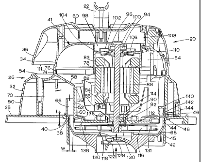
With reference now to Figs. 1-3, a canister type vacuum cleaner 10
includes a debris collection cannister 12 supported upon casters 14. An
aperture
16 is formed in a side of cannister 12 and is adapted to received a vacuum
hose or
similar attachment (not shown). Secured to an open top of cannister 12 by over-
center type latches 18 is a vacuum assembly 20 including a handle 22 and a
power
cord 24.
Referring more particularly now to Fig. 2 and Fig. 3, vacuum assembly
20 includes a housing assembly 26 formed by the joining of a plurality of
housing
members, respectively, members 28, 30, 32, 34 and 36. Preferred housing
members are formed from plastic materials, such as polypropylene,
polyethylene,
ABS and similar materials, and are joined using sonic welding, heat staking,
adhesive bonding, threaded fasteners or combinations of these and other
joining
techniques as are well-known in the art. Member 28 forms a closure for the
open
top of cannister 12 and is retained thereto by latches 18. Member 28 includes
formed offset from its center a flanged aperture 38 including a rabbet 40.
Member 30 forms an upper portion of an impeller housing 42. Member
30 includes a first cylindrical wall portion 44 separated from a second
cylindrical
wall portion 46 by a step offset 48. Wall portion 46 is received through
aperture
38 with stepped offset 48 engaging rabbet 40, and member 30 is then sPcured to
member 28.
Member 32 includes an substantially cylindrical outer wall 50 and a
substantially cylindrical inner wall 52 the upper edges 54 and 56,
respectively, of
which are joined by a wall 58. A lower end 60 of inner wall 52 is enclosed by
an
-5-
CA 02359929 2001-07-24
WO 00/47099 PCT/US99/14698
end wall 62, forming a cavity 64 that makes up a lower portion of a motor
housing
41. Opposite cavity 64, inner wall 52 and end wall 62 form an upper portion of
impeller housing 42.
Inner wall 52 is separated from wall portion 44 defining an annular
passage 66 between an impeller cavity 68 and a discharge plenum 70 formed
between inner wall 52 and outer wall 50. Outer wall 50 includes a plurality of
outlet passage 72 (best seen in Fig. 1) which permit the discharge of working
air
from discharge plenum 70 from the vacuum assembly 20.
Member 34 has a dome configuration and includes a cylindrical flange
74. Wall 58 is formed with an upwardly extending cylindrical flange 76, and
member 34 is disposed over member 32 enclosing cavity 64. Flange 74 engages
flange 76 for locating and securing member 34 to member 32. Member 34 further
includes a cylindrical wall 78 that extends downwardly into cavity 64 from an
upper portion of member 34. Member 36 also has a dome configuration and is
secured over member 34, and handle 22 is formed on an outer upper surface 80
of
member 36.
An electric motor 82 is disposed at its upper end 83 within cylindrical
wall 78 and is supported axially at its lower end 84 on ribs 86. Motor 82
includes
an axially extending motor shaft 88 which projects upwardly from upper end 83
and downwardly from lower end 86. In addition to the bearings supporting shaft
88 within motor 82, shaft 88 may also be journally supported by a bearing 90
retained within a bearing retainer 92 within ribs 86 and by a bearing 94
retained
within a bearing retainer 96 retained within a cylindrical recess 98 formed in
an
upper portion of member 34. A fan 106 is secured to an upper end 100 of shaft
88
-6-
CA 02359929 2001-07-24
WO 00/47099 PCT/US99/14698
adjacent a vent aperture 102 also formed in the upper portion of member 34.
Vent
aperture 102 is defined by a radially inwardly extending flange 104, and fan
106 is
retained on shaft 88 adjacent flange 104. During operation of motor 82, fan
106
draws air into cavity 64 via apertures 110 and upwardly from within cavity 64
and
over motor 82. The air is expelled from vent aperture 102 into a cavity 108
formed between member 34 and member 36 and outwardly from cavity 36 through
opening 111 formed between member 32 and member 36. Therefore, in a
preferred embodiment of the present invention working air is not used for
cooling
motor 82.
A lower end 114 of shaft 88 extends downwardly through an aperture
112 formed in end wall 62 and into impeller housing 68. An impeller 116 is
secured to lower end 114 within impeller housing 68 and adjacent a inlet
passage
118 formed in member 30. Inlet passage 118 includes a downwardly extending
cylindrical portion 120 within which are formed a plurality of louvers 122.
Secured
over inlet passage 118 opposite impeller housing 68 and within cannister 12 is
a
filter retainer 124 and a filter 126, each of which are of typical
construction. Inlet
passage 118 further includes an upwardly extending shroud portion 128 disposed
adjacent a central portion 130 of impeller 116.
When motor 82 is operating, impeller is rotationally driven within
impeller housing 68. As illustrated by the arrows in Fig. 3, working air is
drawn
from cannister 12, through filter 126, through inlet passage 118 to central
portion
130 of impeller 116. Impeller 116 drives the working air radially outwardly
toward
wall 44. A lower portion 45 of wal144 is angled to directed the working air
toward and through annular passage 66. As can be seen from the drawings,
-7-
CA 02359929 2001-07-24
WO 00/47099 PCT/US99/14698
annular passage 66 is formed substantially without obstruction about its
entire
circumference. In addition, annular passage 66 has a substantially constant
width,
"w" in Fig. 3, from an inlet 132 to an outlet 134. In this regard, annular
passage
66 forms a minimum cross-section within the working air discharge path, i.e.,
the
path from the outer circumference 13 1 of impeller 116, into plenum 70 and to
outlets 72. This minimum cross-section creates back pressure for impeller 116
thereby increasing its efficiency. Moreover, because annular passage 66 is
substantially obstruction free, noise normally associated with vanes or other
obstructions in the discharge path for creating back pressure is substantially
reduced or eliminated. It will be appreciated that for various applications
the width
of annular passage 66, and hence the size of the minimum cross-section, may be
adjusted to provide the desired amount of back pressure for optimum impeller
efficiency. As best seen in Fig. 3, wall member 60 extends as a cylindrical
flange
136 adjacent a recess 138 formed in end wall 62. Lengthening or shortening
cylindrical flange 136 correspondingly lengthens or shortens a length "I" of
annular
passage 66, respectively increasing or decreasing the amount of back pressure
it
creates.. Similarly, cylindrical flange may be moved inwardly, towards recess
138,
or outwardly to respectively increase or decrease the width of annular passage
66.
This similarly increases or decreases the amount of back pressure provided by
annular passage 66.
Referring now to Figs. 4 and 5, extending radially outwardly from wall
60 are a plurality of struts 140 including axially extending tabs 142. Wall 46
includes a plurality of inwardly extending and axially aligned slots 144.
Slots 144
are arranged to engage tabs 142 for retaining member 32 to member 34 ensuring
-8-
CA 02359929 2001-07-24
WO 00/47099 PCT/US99/14698
the described configuration of annular passage 66. As will be appreciated,
tabs 142
and slots 144 are disposed across annular passage 66 creating a small but
acceptable obstruction within annular passage 66.. It will be appreciated,
however,
depending on the particular construction of the housing members obstructions
may
be totally avoided and/or one or more small obstructions that do not
significantly
contribute to noise may be disposed within annular passage 66.
Housing members 28, 30, 32, 34 and 36 include various other
structures and features formed therein. These features may add to the strength
of
the member, facilitate alignment or assembly, provide for attaching the
members
and/or provide aesthetics. Several such features are shown in the drawings,
but
have not been individually referenced.
The foregoing description is for the purpose of teaching those skilled in
the art the best mode of carrying out the invention and is to be construed as
illustrative only. Numerous modifications and alternative embodiments of the
invention will be apparent to those skilled in the art in view of this
description. The
details of the disclosed structure may be varied substantially without
departing
from the spirit of the invention, and the exclusive use of all modifications
within the
scope of the appended claims is reserved.
-9-