Note: Descriptions are shown in the official language in which they were submitted.
CA 02360158 2001-10-29
-1-
WASTE AND RECYCLABLE MATERIALS
COMPACTION AND HANDLING APPARATUS
BACKGROUND OF THE INVENTION
This invention relates to improved multifunctional waste and recyclable
materials
compaction and handling apparatus.
The collection of Municipal Solid Waste (MSW), as well as Institutional,
Commercial
and Industrial (ICI) waste has undergone a major transformation in the last 50
years. As more
and more materials are separated form the waste stream and the quantities of
waste generated
have increased, particularly in North America, all types of specialized
equipment have
evolved. This, in combination with ever increasing budget constraints for
municipalities, has
created the opportunity to market a multifunctional collection vehicle that
can handle the
various collection methods as well as material types.
A typical prior art collection apparatus uses a hydraulic mechanism to compact
the
refuse into a storage container. Typically this container is mounted to the
frame of a truck
chassis and has a tailgate rotatably secured to the rear of the container. To
remove the
material from the container, the tailgate is rotated from a down locked
position to an upper
open position. The material is ejected from the container by either rotating
the container from
a lower loading position to an upper dumping position or by using a blade to
push the
material out of the opening created by the open tailgate.
In one version, the collection apparatus has the packing mechanism contained
within
the tailgate. The advantage of this system is that the mechanism can be made
relatively large
to be able to handle a wide variety of materials as well as achieve a high
degree of
compaction. The disadvantages of this arrangement are that more than one
operator is
required because of the walking distance from the cab to the hopper opening
for manual
collection and the requirement to move heavy containers to the compactor for
emptying.
Another disadvantage is that they typically have poor weight distribution
because the packing
mechanism, which is a large percentage of the overall weight, is located
behind the rear axle.
Another typical configuration is a body that loads from the front of the
chassis using
arms to pick up containerized material. The container is rotated over the cab
of the chassis to
empty material into the loading hopper. The mechanism includes is a blade
which pushes the
material into the storage container. The advantage of these units is that one
operator can
CA 02360158 2001-10-29
-2-
empty containers and achieve a substantial payload. One disadvantage of this
configuration is
the access space required to hook onto the containers. Another disadvantage is
that the
substantial mechanism required to lift the containers over the cab is heavy
and requires a
large chassis to operate practically. A side effect of the mechanism handling
the container is
the damage to the containers and their lids.
Similar body configurations, with the packing mechanism mounted above the
chassis
frame to compact material to the rear storage container, have side mounted
equipment to lift
and rotate containers to empty the contents into the charging hopper. The
advantage of this
type of equipment is that the automated collection of containers by one
operator is very
efficient. The disadvantage of these units is that the initial capital costs
and the specialized
and dedicated applications they are designed for limits their flexibility,
including the size of
containers that can be collected and types of material collected. In this type
of unit the
compaction mechanism can be either a push blade, a "pendulum" packer which
rotates down
and to the rear or a "paddle" packer which moves the material to the rear
storage container by
sweeping from side to side in a rounded hopper.
A slightly different configuration, which also uses a packing blade to push
material
from the front charging hopper to the rear storage container, uses a drop
frame to lower the
packing mechanism to allow for manual collection. The advantage of this
configuration is the
capability for one operator to collect door to door manually, or, with the
appropriate
additional mechanism, semi-automated or automated carts. The disadvantage of
these types
of units is the requirement to modify the chassis frame. The relatively high
loading height
even with the drop frame, and the relatively small charging hopper limits the
size of material
that can be handled as well as the size of carts or containers that can be
dumped.
In all of these configurations, the packing mechanism moves the material in
one
direction. The paddle packer, even though it moves in a rotary action from
side to side, only
moves the material to the into the storage container to the rear of the paddle
and effectively
acts like a single direction push blade. This operation in one direction is
the simplest and
most effective for many specialized applications but limits the versatility
for multiple
applications.
Except for the unit described with the packing mechanism in the tailgate, all
of the
other units require a chassis with a substantial wheelbase to accommodate the
packing
mechanism between the chassis cab and the storage container. The long
wheelbase, which
CA 02360158 2001-10-29
-3-
limits the units manoeuverability, restricts these units from certain tight
areas and slows the
collection process in areas where turns cannot be achieved without backing up.
Other units on the market have loading hoppers on the side which also act as
the
compacting mechanism. The advantage of these units is that they overcome the
turning
radius problems and versatility constraints of the aforementioned
configurations but have
limited compaction capability. The large loading/packing mechanism allows for
collection of
virtually any size or type material in the MSW and ICI streams, but the length
of the packing
mechanism and the packing motion from side to side, limits the payload for
some materials.
There are several issues beyond the personnel requirements and route planning
that
affect the operational efficiency of a collection program. As traffic becomes
more and more
abundant in many municipalities, the turn around time to dispose of the waste
and return to
the collection route increases. Also, the distance required to travel to
landfills is increasing as
old landfills are filled and new landfills are located further from the urban
areas. Another
important issue is the separation of material for recycling. Many of the
aforementioned units
can collect some separated materials but have difficulty or practically cannot
collect a
complete range of materials. As previously mentioned, the collection operation
must be done
in spite of ever increasing budget constraints on parks, municipalities and
regional districts.
In view of the aforementioned problems, it would be desirable if a refuse
compaction
and handling apparatus could be provided which would overcome the above
disadvantages
while retaining as many of the advantages as possible. A collection body that
could be
installed on a wide variety of chassis including single rear axles as well as
larger tandems,
would provide a cost efficient solution for a range of collection
requirements. A collection
body that could collect material in three different ways, i.e., manually, or
using semi-
automated or automated carts, as well as large containers for recycling and
ICI collection,
would provide the utility required by smaller operations and the efficiency
required for larger
operations. In addition, it would be desirable to provide a compaction
apparatus that could
collect bulky recyclables like old corrugated cardboard in addition to MSW and
ICI waste.
In addition, it would be desirable to provide a refuse compacting apparatus
that would
balance the load between the front and rear axles to optimize the chassis
capability and allow
for the purchase of the least expensive chassis for a desired payload.
CA 02360158 2004-02-12
-4-
SUMMARY OF THE INVENTION
In an effort to provide a solution to the aforementioned problems, the present
invention provides a refuse/recyclable materials compaction and handling
apparatus which is
versatile in both the types of collection that can be achieved, the types of
material that can be
collected, as well as the types of chassis that the storage
container/compaction apparatus can
be mounted on. Accordingly, the refuse/recyclables compaction and handling
apparatus of the
invention addresses the complex and often contradictory demands of collecting
manually as
well as with containerization, mixed waste as well as source separated
materials and payload
optimization on various chassis configurations.
Accordingly the invention provides a waste and recyclable materials compaction
and
handling apparatus including: a storage container for the materials; an
elongated charging
hopper defined and connected adjacent to and alongside said storage container
for receiving
the materials, said charging hopper including openings defining pathways
leading into the
interior of said storage container; a packing head mounted for travel in both
rearward and
forward directions within and along said charging hopper between end portions
thereof; at
least one driver connected to said packing head to effect the travel thereof
in said directions
along and within said charging hopper between positions adjacent said hopper
end portions;
and said packing head having opposed packing faces adapted to engage the
materials placed
in said charging hopper such that as said packing head is made to travel along
and within said
charging hopper by said at least one driver, said materials are compacted
within and
positively forced from the charging hopper through said pathways and thence
into the interior
of the storage container.
In a preferred form of the invention the packing head is mounted for travel
along an
elongated support assembly extending lengthwise of said charging hopper.
Furthermore said
at least one driver preferably comprises at least one hydraulic packing
cylinder extending
lengthwise of said charging hopper.
In a preferred embodiment said support assembly and said at least one
hydraulic
cylinder extend along a side portion of said charging hopper, said charging
hopper being
located along a lower portion of said storage container. Preferably a pair of
said hydraulic
packing cylinders is provided, each being adapted for moving the packing head
in a
respective one of rearward and forward directions of travel.
CA 02360158 2004-02-12
-5-
According to a further preferred feature said storage container includes wall
portions
contoured to assist in movement of the materials being compressed by said
packing head
through said openings and into and within the interior of the storage
container. Desirably,
said wall portions comprise a frontal contoured end section and a rear
contoured end section
of said storage container both shaped to facilitate said movement of the
materials into and
within said storage container. A further preferred feature is that said rear
end section is
hinged to provide a tailgate which can be opened to permit the contents of the
storage
container to be dumped. Pivotal connections for securing the compaction and
handling
apparatus to the chassis of a transport vehicle are typically provided along
with mechanisms
for opening and closing said tailgate in the course of a dumping procedure.
A further desirable feature includes a clean out panel mounted for pivotal
movement within
the storage container adjacent said frontal end section, and an actuator for
pivoting said clean out
panel to dislodge materials adjacent said frontal end section.
In a preferred form of the invention a loading hopper is mounted adjacent to
and
alongside said charging hopper for movement from a first lowered position to
permit ready
filling of the loading hopper to a second raised position above the charging
hopper for
dumping of materials into the charging hopper. Preferably said loading hopper
has a
retractable side wall which moves to enlarge the capacity of the lading hopper
during filling
and which partly closes during movement to the second raised position.
In operation, as the packing head moves back and forth within the charging
hopper, the
material is compacted into both the front and rear of the storage container.
The preferred shape of the
container allows the material to flow in all directions and fill the storage
container to capacity.
As noted above, a support assembly is preferably provided to house one or more
hydraulic cylinders which provide the motive force to cycle the packing head
from the front
to the rear of the charging hopper and back. The cylinder(s) provide
sufficient pressure to the
packing head to force the materials into the storage container through
openings at each end of
the charging hopper. The size of the openings at the ends of the charging
hopper may be
adjustable to accommodate different materials.
As noted above, suitable means may be provided for loading material into the
charging hopper. Although loading can be done manually directly into the
charging hopper,
this would not be practical for most applications. Therefore, means are
preferably provided to
accept materials from a lower loading position and to move the materials to a
higher
unloading position partially or completely inverted over the charging hopper.
CA 02360158 2001-10-29
-6-
One preferred such means as noted above is a loading hopper that is sized for
the
appropriate application. The hopper rotates from a lower loading position to a
higher,
partially or completely inverted dumping position. In the simplest
configuration, this hopper
has a fixed volume with a loading height appropriate to the application. In
another
configuration the loading hopper maybe provided with a retractable side wall
that opens to
accept a large quantity of material, and which retracts in cooperation with
the storage
container and charging hopper as it rotates from the lower loading position to
the higher,
unloading position. This configuration would be compatible for dumping
containers with a
fixed frame and a rotatable hopper. In an additional configuration, the
loading hopper may be
equipped with a means to unload carts or containers for semi-automated
collection. The
hopper may also be modified or eliminated completely and replaced with a means
to dump
carts or containers for automated collection.
BRIEF DESCRIPTION OF THE DRAWINGS
Fig. 1 is a perspective view of a waste/recyclables materials compaction and
handling
apparatus in accordance with a preferred embodiment of the invention when
mounted on a
suitable vehicle;
Fig. 2 is a perspective view of the compaction and handling apparatus with the
loading hopper removed and looking generally downwardly into the charging
hopper from
the rear of the apparatus;
Fig. 3 is a further perspective view very similar to Fig. 1 but with the
loading hopper
removed so as to show the underlying assemblies;
Fig. 4 is a transverse vertical section view taken through the storage
container and
charging hopper showing the packing head, container divider wall, and certain
external panels
of the storage container;
Fig. 5 is a top plan view of the truck mounted compaction and handling
apparatus
showing the relative positions of the storage container, charging hopper,
packing head and
related assemblies;
Fig. 6 is a perspective inside view of a portion of the compaction assembly
showing
the packing head and the packing cylinder frame assembly along which the
packing head
travels;
CA 02360158 2001-10-29
-7-
Fig. 7 is a further perspective view showing the outside of the compacting
assembly
including the packing cylinder frame assembly, the packing cylinders, and the
packing head
support arrangements;
Fig. 8 is a further perspective of the complete compaction and handling
appaxatus as
in Fig. 1 but with the compaction and handling apparatus in the raised dumping
position with
the tailgate open;
Fig. 9 is a partial horizontal section view taken at the frontal end of the
storage
container and looking downwardly from above and illustrating the pivotally
mounted clean
out panel and its actuating cylinder;
Fig. 10 is a cut-away perspective view of the frontal portion of the storage
container
and looking generally inwardly and forwardly and illustrating the pivotally
mounted clean out
panel and associated assemblies;
Fig. 11 is a perspective view looking generally upwardly and toward the rear
of the
apparatus and illustrating the rear tailgate locking assembly;
Fig. 12 is a partial longitudinal section view further illustrating the
tailgate locking
actuator and associated linkages;
Fig. 13 is a further perspective view similar to Fig. 1 but with a manual
loading
hopper in the fully opened or down position;
Fig. 14 is a perspective view similar to Fig. 13 but showing a modified
extendable
loading hopper with an extendable panel arrangement to provide greater
capacity;
Fig. 15 is a transverse view looking toward one end of the loading hopper
illustrated
in Fig. 14 with such hopper in the raised dumping position and illustrating
various linkages
and actuator mechanisms associated with the loading hopper;
Fig. 16 is a view similar to Fig. 15 and showing the relative positions of the
various
linkages when the hopper is in the fully raised travel position above the
charging hopper;
Fig. 17 is a perspective view of the compaction and handling apparatus with a
modified form of loading hopper in the open position in engagement with a roll
out cart
which has been moved into a position ready to be dumped;
Fig. 18 is a transverse view partly in section showing the loading hopper in
elevation
along with its associated mechanisms together with the roll out cart which has
been raised
upwardly in the dumping position along with the loading hopper;
CA 02360158 2001-10-29
-8-
Fig. 19 is a perspective view similar to Fig. 14 showing the compaction and
handling
apparatus with extendable loading hopper, such apparatus being equipped with
an extendable
arm assembly having an actuator thereon for tipping a container assembly;
Fig. 20 is a front elevation view of the compaction and handling apparatus
with the
extendable loading hopper in the loading position with the extendable arm and
actuator
located in a position to engage a tiltable hopper assembly; and
Fig. 21 is a view similar to Fig. 20 but taken from the rear and showing the
hydraulic
actuator extended such that the container has been raised into the tipping
position whereby
materials therein are dumped into the extendable loading hopper.
DETAILED DESCRIPTION OF PREFERRED EMBODIMENTS
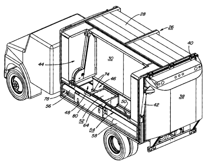
Referring now to the drawings, Figs. 1 and 2 are perspective views of the
materials
compaction and handling apparatus 20 mounted on the chassis 22 of a truck 24.
The
apparatus 20 includes a storage container 26 including a top wa1128, a
vertical divider wall
pane130, exterior wall panel 32, a floor 34 (see Fig. 4), and opposed smoothly
convexly
curved frontal 36 and rear panels 38. The rear pane138 defines a tailgate
which is hinged
along its upper edge by conventional tailgate hinges 40 and this tailgate is
opened and closed
by a tailgate hydraulic cylinder 42. The lower edge portion of the tailgate is
provided with a
tailgate lock assembly to be described hereafter.
Fig. 1 shows the compaction and handling apparatus 20 together with a side
mounted
loading hopper 110, 114 (to be described hereafter) in the raised travel
position and disposed
intermediate the frontal and rear portions of the storage container 26 in a
loading hopper
recess 44 located above an elongated charging hopper 46 which is easily seen
in Figs. 2 and
subsequent figures.
Referring to Figs. 2 - 5 (which omit the loading hopper) it will be seen that
the
elongated charging hopper 46 is defined adjacent to and alongside the storage
container 26
and that it extends along a lower portion of the storage container 26 in close
proximity to and
is partly defined by the above-mentioned divider panel 30. This elongated
charging hopper
46 is provided with opposed open end portions 48, 50 which define pathways
leading into the
interior of the storage container. The size of these pathways may be varied
somewhat
depending on the nature of the materials being handled. A packing head 52 is
mounted for
travel within and along the charging hopper 46 between the open end portions
48, 50. The
packing head 52 is mounted for travel along an elongated support assembly 54
which extends
CA 02360158 2001-10-29
-9-
lengthwise of the charging hopper 46 and which, in part, serves to define an
outer wall of
same. Packing head 52 is driven to and fro along the lengtr.i of the charging
hopper 46 by
means of a pair of packing cylinders namely a forward packing cylinder 56 and
a rear packing
cylinder 58.
The smoothly convexly curved frontal wall section 36 of the storage container
26 and
the correspondingly convexly contoured tailgate 38 of the storage container
both assist in
facilitating movement of the materials being handled through the passageways
defined by the
open end portions 48, 50 of the charging hopper and in helping material flow
to completely
fill the storage container.
The packing head 52 and its support and drive assemblies are best seen in
Figs. 6 and
7. The support frame assembly 54 includes an elongated packing cylinder frame
60, an upper
portion of which is provided with a packing head support rail 62. The packing
head 52 is
provided with a slider assembly 64 which slides along the support rai162, this
slider assembly
64 being provided with suitable wear strips 66 of a material selected to
reduce wear and
friction. Slider assembly 64 is fixed to an outer box assembly 80 (Fig. 7) via
which forces
from the packing cylinders are transferred to the packing head 52 as described
hereafter. The
packing cylinder frame 60 is also provided with an elongated corner guide 68
extending along
the lower inner surface portion of the packing cylinder frame 60 thereby to
provide additional
support for the packing head 52 as it is moved along the packing cylinder
frame by the
aforementioned packing cylinders 56, 58.
The packing head 52 itself is of a sturdy reinforced box-like structure and
includes
opposed packing head faces 70, 72 which engage the materials being handled as
the packing
head 52 travels along and within the charging hopper 46 in the course of
operation.
The lower portion of the divider pane130 is also provided with a spaced apart
parallel
pair of elongated packing head support strips 74 (Fig. 2) which engage mating
wear elements
76 formed on the inner distal end portions of the packing head 52 thereby
assuring that the
packing head is securely supported during the course of its movement along and
within the
charging hopper 46. It will be appreciated that since relatively high
compaction forces are
exerted, that the packing head 52 and its associated assemblies together with
the storage
container 26 must all be sturdily constructed to withstand the relatively
substantial
compression forces involved. This also applies to the packing cylinder frame
60 previously
referred to including the packing cylinder end frames 78 against which the
forward and rear
packing cylinders 56, 58 abut. It should be noted here that the two packing
cylinders 56, 58
CA 02360158 2001-10-29
-10-
are located in spaced parallel relationship to one another with the forward
packing cylinder 56
being disposed above the rear packing cylinder 58 with the rams of the two
cylinders
engaging within the outer box assembly 80 (Fig. 7) via which the forces
exerted by the two
cylinders are transmitted through slider assembly 64 to the packing head 52
per se. This box
assembly 80 is provided with apertures in its opposing ends into which the
opposing packing
cylinders56, 58 can enter as the packing head assembly (i.e., the packing head
52 and box
assembly 80) is driven from one end of the packing cylinder frame to the other
during the
course of normal operations.
Fig. 8 shows the truck mounted compaction and handling apparatus 20 in the
raised
dumping position with the tailgate 38 open. It will be seen that the underside
of the
conlpaction and handling apparatus 20 is provided with a sturdy frame
construction 82 and
that the rearward end portion of same is provided with suitable pivot hinges
84 which are
pivotably secured to the rear end portion of the truck chassis 22. A
conventional dumping
actuator 86 is provided to effect dumping of the assembly. The previously
noted tailgate
actuator cylinder 42 is shown in the extended position with the tailgate in
the full open
position.
Fig. 9 is a partial section view taken at the frontal end of the storage
container 26
looking downwardly from above and illustrating a pivotally mounted clean-out
panel 88 and
its actuating cylinder 90. Referring to Fig. 10 which is cutaway perspective
view of a frontal
portion of the storage container 26 looking generally inwardly and forwardly,
it will be seen
that the clean-out pane188 is mounted by way of upper and lower panel hinges
92 so that
when the actuating cylinder 90 is operated, the clean-out pan.e188 pivots with
a sweeping
motion thereby to clear out materials which may tend to hang up in the upper
corner portion
of the curved frontal wal136 of the storage container. The actuating cylinder
90 is normally
retained in the retracted condition during the loading/packing procedures and
the clean-out
pane188 is activated in the course of unloading/dumping of the storage
container 26 thereby
to ensure full clean out is accomplished.
Referring to Figs. 11 and 12, it will be seen that Fig. I 1 is a perspective
view looking
generally upwardly and toward the rear of the storage container 26 and
illustrating the rear
tailgate locking assembly 94. Fig. 12 further illustrates the tailgate locking
actuator and
associated linkages. Tailgate locking assemblies are, in general, well known
in the art and an
important factor is that the locking assembly be sturdily constructed to
withstand the
substantial compaction forces exerted. With reference to Fig. 12 there is
shown a lock
CA 02360158 2008-09-15
-11-
actuator cylinder 96 mounted to the storage container underframe which
cylinder 96 engages
a tailgate lock pivot linkage 98 which, in turn, is connected to a tailgate
lock link 100 and
this, in turn, is connected to the elongated tailgate lock 102 which is
pivotally connected
(104) to a rearward portion of the storage container frame. This lock 102 is
adapted to
engage a lip portion 106 extending along the lower edge of the tailgate 38 to
securely hold
the tailgate in the closed position. When the lock actuating cylinder 96 is
extended however,
the above-described linkages rotate the tailgate lock 102 to the open or
released position
thereby allowing the tailgate to open.
Referring to Fig. 13, there is shown a perspective view of the complete
apparatus 20
with a manual loading hopper 110 shown as being mounted adjacent to and
alongside the
charging hopper 46 for movement about pivot hinges from the lowered position
shown to
permit filling of the loading hopper 110 to a raised position within recess 44
generally above
the charging hopper 46 for dumping of the materials into the charging hopper.
This
movement of the loading hopper 110 is effected by way of a pair of elongated
loading hopper
actuating cylinders 112 interconnected between the opposing ends of the
loading hopper and
upper portions of the storage container generally as shown.
An extendable loading hopper 114 is illustrated in Figs. 14 - 16. Here it will
be seen
that the extendable loading hopper is provided with a pivotally mounted panel
116 which
effectively acts to increase the capacity of the loading hopper. This panel is
hinged to the
main body of the hopper 114 along its lower edge and it is provided with
opposed triangle-
shaped end panels which cooperate with the end panels of the loading hopper
114 to prevent
spillage of materials. Elongated gas shocks 120 extend between the main body
of the loading
hopper and the extendable panel as shown.
Referring now to Figs. 15 and 16, further details of the above-noted
assemblies are
shown. The extendable loading hopper 114 is hinged adjacent opposing ends of
the charging
hopper by way of spaced-apart loading hopper hinges 122. The hopper or
actuating cylinders
112 each extend between an upper attachment points 124 and a lower loading
hopper link
126 as well as well as a doglegged shaped pivot link 128, the lower end of
which is affixed to
the loading hopper support assembly. The extendable panel is shown connected
by the
extendable panel hinges 130 to the loading hopper 114 per se. The gas shock
120 is also
shown as extending between the extendable panel and the loading hopper per se.
The upper
distal edge portion of the extendable panel is provided with rollers 132 which
engage curved
CA 02360158 2008-09-15
-12-
roller guides 134 which extend inwardly and hence downwardly along opposed end
portions
of the inner divider panel 30 of the storage container (see also Fig. 14.).
With the loading hopper 114 in the partially raised position shown in Fig. 15,
the
rollers 132 on the upper edge of the extendable panel 116 have just begun to
contact the roller
guides 134. As the loading hopper is made to rotate counterclockwise by way of
the hopper
lifting cylinders 112, the roller guides 134 interact with the rollers 132
thus causing the
extendable panel 116 to be pivoted towards the main body of the loading hopper
against the
relatively small forces exerted by the gas shocks 120. In fact these gas
shocks exert just
enough force as to prevent premature closure of the extendable panels 116.
Since the
materials which were in the loading hopper are relatively quickly released
into the charging
hopper 46, the closure of the extendable panel is not impeded and rotation of
the entire
loading hopper continues into the fully upright travel position illustrated in
Fig. 16 with the
loading hopper 114 positioned within loading hopper recess 44 directly above
the charging
hopper 46. At this point it will be seen that the extendable panel is fully
closed. When the
reverse action occurs, i.e., as the loading hopper 114 is pivoted outwardly,
the gas shocks 120
act to extend the extendable panel with the rollers 132 travelling along the
roller guides and
controlling the extent of the panel opening process.
Fig. 17 and 18 illustrate the simple manual loading hopper 110 depicted in
Fig. 13
when used in conjunction with a specially designed rollout cart 140 which is
provided with
suitable hooks to engage the frontal ledges of the loading hopper 110 so that
as the loading
hopper is swung to the dumping position shown in Fig. 18, the rollout cart is
also swung
upwardly along with it such that the contents of the rollout cart are dumped
directly into the
charging hopper 46. This relatively simple adaptation offers obvious time and
labour saving
advantages.
Fig. 19 is a further perspective view showing the compaction and handling
apparatus
with the extendable loading hopper 114 as described previously and wherein the
vehicle is
equipped with an extendable arm 142 having a hydraulic actuator cylinder 144
thereon
arranged for tipping a ground mounted container assembly. A vehicle mounted
extendable
arm assembly having an actuator thereon adapted for tipping a container
assembly of this
nature is described in my U.S. Patent 6,077,020 issued June 20, 2000.
With particular reference to Fig. 20 there is shown a front elevation view of
the
compaction and handling apparatus 20 with the extendable loading hopper 114 in
the
CA 02360158 2001-10-29
-13-
downwardly located loading position. The extendable arm 142 is in its
outwardly extended
position and the hydraulic actuator 144 has been located in the required
position so as to
engage between a tiltable container 146 and the frame 148 upon which it is
mounted.
Fig. 21 is a view similar to Fig. 20 but taken from the rear. This figure
shows the
hydraulic actuator 144 in its extended condition such that the container 146
has been raised
and tilted around into the tipping position such that its lid 150 has
automatically opened
thereby to discharge the materials therein into the extendable loading hopper
114 described
previously. Following discharge of the materials, the hydraulic actuator 144
is retracted such
that as the container 146 rotates back into the loading position as shown in
Fig. 20, the
extendable arm 142 is retracted along with the hydraulic actuator cylinder and
stowed
alongside the chassis of the vehicle, and thereafter, the loading hopper lift
cylinders 112 are
actuated thereby to swing the extendable loading hopper 114 around such that
its load is
discharged into the charging hopper 46 in the manner described above. When the
loading
hopper has reached the travel position above the charging hopper, the vehicle
moves away to
a further collection site.
As will be apparent from the description set out above, once the materials
have been
received into the charging hopper 46, the packing cylinders 56, 58 are
activated to cycle the
packing head 52 along the charging hopper thereby to force the materials
through the forward
or rear opening 48, 50 described previously and into the storage container 26.
For example,
when the forward packing cylinder 56 is fully extended and the packing head 52
is at the rear
of the charging hopper 46, the hydraulics are reversed, by any well-known
means, and the
rear packing cylinder 58 is activated to move the packing head 52 toward the
front of the
charging hopper 46. This back-and-forth motion empties the charging hopper 46
and.
compacts the material into the storage container 26 through the passageways
defined by the
openings 48, 50 referred to previously. Once the material passes through these
openings, the
material is guided by the convexly-curved front end section and the convexly-
curved rear
tailgate 38 in such a way as to assist in completely filling the storage
container 26.
When the storage container 26 is to be emptied, the rear tailgate is unlocked
by the
mechanisms described above and rotated around the upper hinges from a position
approximately perpendicular to the storage container floor to a position
approximately
parallel to that floor. Dumping actuator 86 then rotates the entire compaction
and handling
apparatus approximately 45 to empty the contents thereof through the opening
created by
the open tailgate. Removal of the material from the front of the storage
container 26 will of
..~..
CA 02360158 2001-10-29
-14-
course be assisted by the previously described clean-out pane188 which is
rotated by its
associated actuator to assist in sweeping away any materials which might tend
to lodge
adjacent the front of the container.
The addition of the manual loading hopper 112 to the apparatus allows for
material to
be collected at a lower loading height. As described above, such hopper is
emptied by
rotation of same about the loading hopper hinges from the lower receiving
position to the
upper dumping position. This is accomplished through the use of the actuators
112 acting via
the loading hopper linkage arrangement and pivot linkage described above.
The extendable loading hopper 114 described previously rotates in the same
manner
as the manual loading hopper but has the additional feature of the extendable
panel 116. The
extendable panel rotates outwardly from the this hopper when large quantities
of material are
received. As this hopper is rotated from the lower receiving position to the
raised dumping
position, the rollers described previously come into contact with the roller
guides 134 which
provides an ever decreasing arc to gradually collapse the gas shock 120 and
thus rotate the
extendable panel into the hopper body as the material is emptied. When this
rotation is
completed the extendable hopper is approximately directly over the packing
head 52 and the
charging hopper 46and in the travel position within the loading hopper recess
44.
Preferred embodiments of the invention have been described by way of example.
Those skilled in the art will realize that various modifications and changes
may be made
while remaining within the spirit and scope of the invention. Hence the
invention is not to be
limited to the embodiments as described but, rather, the invention encompasses
the full range
of equivalencies as defined by the appended claims.