Note: Descriptions are shown in the official language in which they were submitted.
CA 02360253 2001-10-26
-1_
MEDIA CASSETTE FOR AUTOMATIC DISPENSER
BACKGROUND OF THE INVENTION
s 1. Field of the Invention
The present invention relates to a media cassette for an automatic
dispenser such as a paper currency dispenser and particularly, to a media
cassette for an automatic dispenser in which a push plate locking latch in the
to media cassette is automatically unlatched when the media cassette is
received in
the automatic dispenser.
2. Description of the Background Art
is Generally, an automatic dispenser is applied to automatic teller machines
(ATMs). An ATM generally is provided with a space for receiving a media
cassette
to store cash (paper currency) which is a medium and with a door for locking
the
media cassette after receiving the media cassette therein.
Figure 1 is a top plan view showing a conventional media cassette for an
2o automatic dispenser and Figure 2 is a front view showing the conventional
media
cassette for an automatic dispenser.
The conventional media cassette for the automatic dispenser includes a
cassette body 102 having an interior space in which media may be stored, a
push
plate 104 installed slidably in the cassette body 102 for supporting media
received
2s in the cassette body 102, a spring 106 positioned between the push plate
104 and
CA 02360253 2001-10-26
-2-
an inside wall of the cassette body 102 for urging the push plate 104, and a
guide
installed between the push plate 104 and the cassette body 102 for slidably
supporting the push plate 104.
The cassette body has a rectangular shape with the one side opened and
s a guide line 108 which is slid at the upper side when the media cassette is
installed in the automatic dispenser.
The push plate 104 is positioned movably in the cassette body 102
standing upright and at the one upper end of the cassette body, a handle 110
is
formed which a user can hold and pull out. As mentioned between the rear
surface
io of the push plate 104 and the inner rear wall surface of the cassette body
102, a
spring 106 is installed to provide an elastic force to the push plate 104.
The guide includes a guide rails 112 which are installed on the both inner
side walls of the cassette body 102 in the longitudinal direction thereof and
guide
rollers 114 which are installed at the both sides of the push plate 104
rotatably and
is abutted to the respective guide rails 112.
The guide rollers 114 are supported on rotation shafts 116 which are
installed at both sides of the push plate 104 in the upright direction.
The operation of the conventional media cassette for an automatic
dispenser will be described as follows.
2o If the handle 110 formed in the push plate 104 is pulled to the rear, the
push plate 104 moves rearwardly overcoming the elastic force of the spring
106.
After moving the push plate 104, media are received to the inside of the
cassette
body 102 sequentially with the push plate 104 being held back manually to
prevent
the push plate 104 from moving forwardly.
2s In case the handle 110 of the push plate 104 is released after completing
CA 02360253 2001-10-26
-3-
loading of the media, the push plate 104 moves forwardly by the elastic force
of
the spring 106 and the media between the cassette body 102 and the push plate
104 is pressed by a certain elastic force. Once the loading is completed, the
media
cassette is ready to be installed and used for the automatic dispenser.
s However, the conventional media cassette for the automatic dispenser has
problems that the operation is difficult, the operation time is long and
inferior
results are produced in case of installing it in the automatic dispenser due
to the
irregular reception of the media after the operation since a user must move
the
support plate rearwardly and hold it so that it with one hand cannot move
forwardly
~o while holding the media into the cassette body with the other hand.
To solve the above problem, a locking tool is installed between the support
plate and the cassette body, the push plate is pulled backed and locked, media
is
loaded, and when a locking release button is pushed, locking of the push plate
is
released thus to support the media.
is However, in the above conventional media cassette, locking of the push
plate must be released before loading the media cassette into the automatic
dispenser. In case the user loads the media cassette into the automatic
dispenser
without pushing the locking release button by mistake, there occurs a problem
that
the media are not supplied to the dispenser because the push plate is held in
the
20 locked state.
Also, since the conventional media cassette can store only one kind of
media, media of different sizes can not be stored thus to limit the usage of
the
cassette.
2s SUMMARY OF THE INVENTION
°
CA 02360253 2004-10-12
-4-
Therefore, certain specific embodiments of the present invention provide a
media cassette for an automatic dispenser which can be used easily and which
solves
the problems of incorrect operation in case of loading a cassette with a
locked push
plate since locking of the push plate is automatically released if the
automatic
dispenser receives the cassette with a locked push plate.
Another advantage flowing from certain embodiments is the provision of a media
cassette for an automatic dispenser which can store many kinds of media having
different sizes since the width of the cassette body can be changed according
to the
size of the stored media thus to broaden the usefulness.
To achieve these and other advantages, in accordance with one aspect of the
present invention, there is provided a media cassette for an automatic
dispenser,
comprising a cassette body having an interior space in which media to be
dispensed
may be received, a push plate installed slidably in the cassette body for
supporting
media received therein, an elastic member positioned between the push plate
and the
cassette body for urging the push plate, guide means installed between side
surfaces
of the push plate and inner sides of the cassette body for guiding the push
plate to
perform linear movement, and locking means installed between the push plate
and the
cassette body for locking the push plate to the cassette body and for
automatically
releasing the locking of the push plate when the media cassette is inserted
into an
automatic dispenser.
The guide means comprises a guide rod installed at each side of the cassette
body and extending in a longitudinal direction thereof and a guide hole formed
at each
side of the push plate and respectively fixed slidably to the
CA 02360253 2001-10-26
-5-
corresponding guide rod.
A bushing is fixed inside each guide hole to facilitate sliding of the push
plate.
The locking means comprises a hook part coupled to a rear wall of the
s cassette body and protruded to the inner side of the cassette body for
performing
locking operation of the push plate, a hook assembly having a locking release
button part protruded to the outside of the cassette body for being operated
when
the cassette is inserted into an automatic dispenser, to release the locking
and a
latching pin provided on the push plate and engageable by the hook assembly.
Io The hook assembly comprises a bracket which is fixed an the installing
hole formed in the cassette body, a hinge shaft fixed to the bracket, a hook
member having a side protruded to the inner side of the cassette body forming
a
hook part which is protruded outwardly from the cassette body and engageable
with the latching pin and another side having a locking release button part
for
~s releasing latching operation and being rotatable on the hinge shaft and a
return
spring for urging the hook member to its original position on the hinge shaft.
The locking release button part of the hook member is formed protruded
outwardly of the cassette body at a certain angle so that the button can be
pushed
and operate when a door of the automatic dispenser is closed.
2o The latching pin is fixed to two mounting parts which are protruded at a
certain interval from the rear surface of the cassette body.
A retaining ring is fixed at each end of the latching pin.
The media cassette for an automatic dispenser comprises a cassette body
having an interior space in which media to be dispensed may be received, a
push
2s plate installed slidably in the cassette body for supporting media received
therein,
CA 02360253 2001-10-26
-6-
an elastic member positioned between the push plate and the cassette body for
urging the push plate, a guide means installed between each side of the push
plate and each side of the cassette body to guide the push plate to perform
linear
movement and a width varying means installed on a bottom surface of each sides
s of the cassette body for varying the width of the interior space in the
cassette body
according to the size of media to be received therein.
The width varying means comprises a support panel installed at each side
of the cassette body extending in a longitudinal direction for supporting both
side
edge of the media, position determining holes formed in a bottom surfaces at
both
to sides at the cassette body at intervals so that the position of the support
panels in
a transverse direction of the cassette body can be changed according to the
size
of the media to be received in the cassette body and position fixing bolts for
fixing
the support panels in the position determining holes.
The media cassette for an automatic dispenser comprises a cassette body
is having an interior space in which media to be dispensed can be received, a
push
plate installed slidably in the cassette body for supporting media received
therein,
an elastic member positioned between the push plate and the cassette body for
urging the push plate, a guide means installed between each side surfaces of
the
push plate and inner sides of the cassette body for guiding the push plate to
2o perform linear movement, a locking means installed between the push plate
and
the cassette body for locking the push plate and releasing the locking of the
push
plate when the media cassette is inserted into the automatic dispenser and a
width
varying means installed on a bottom surface at both sides of the cassette body
for
varying the width of the cassette body according to the media to be received
2s therein.
' CA 02360253 2004-10-12
-7-
In accordance with another aspect of the invention, there is provided a media
cassette for an automatic dispenser. The media cassette includes a cassette
body, a
push plate, an elastic member, guide means, and locking means. The cassette
body
has an interior space in which media to be dispensed may be received. The push
plate
is installed slidably in the cassette body for supporting media received
therein. The
elastic member is positioned between the push plate and the cassette body for
urging
the push plate. The guide means is installed between side surfaces of the push
plate
and inner sides of the cassette body for guiding the push plate to perform
linear
movement. The locking means is installed between the push plate and the
cassette
body for locking the push plate to the cassette body and for automatically
releasing the
locking of the push plate when the media cassette is inserted into an
automatic
dispenser. The guide means includes a guide rod installed at each side of the
cassette
body and extending in a longitudinal direction thereof, and a guide hole
formed at each
side of the push plate and respectively fixed slidably to the guide rod.
In accordance with another aspect of the invention, there is provided a media
cassette for an automatic dispenser. The media cassette includes a cassette
body, a
push plate, an elastic member, a guide means, and a width varying means. The
cassette body has an interior space in which media to be dispensed may be
received.
The push plate is installed slidably in the cassette body for supporting media
received
therein. The elastic member is positioned between the push plate and the
cassette
body for urging the push plate. The guide means is installed between each side
of the
push plate and each side of the cassette body to guide the push plate to
perform linear
movement. The width varying means is installed on a bottom surface of each
sides of
the cassette body for varying the width of the interior space in the cassette
body
according to the size of media to be received therein. The width varying means
includes a support panel installed at each side of the cassette body extending
in a
longitudinal direction for supporting both side edges of the media, and
further includes
position determining holes formed in a bottom surface at both sides of the
cassette
body at intervals so that the position of the support panels in a transverse
direction of
the cassette body can be changed according to the size of the media to be
received in
the cassette body. The width varying means also includes position fixing bolts
for fixing
the support panels in the position determining holes.
~
CA 02360253 2004-10-12
-7A-
In accordance with another aspect of the invention, there is provided a media
cassette for an automatic dispenser, including a cassette body, a push plate,
an elastic
member, a guide means, a locking means, and a width varying means. The
cassette
body has an interior space in which media to be dispensed can be received. The
push
plate is installed slidably in the cassette body for supporting media received
therein.
The elastic member is positioned between the push plate and the cassette body
for
urging the push plate. The guide means is installed between each side surfaces
of the
push plate and inner sides of the cassette body for guiding the push plate to
perform
linear movement. The locking means is installed between the push plate and the
cassette body for locking the push plate and releasing the locking of the push
plate
when the media cassette is inserted into the automatic dispenser. The width
varying
means is installed on a bottom surface at both sides of the cassette body for
varying
the width of the cassette body according to the media to be received therein.
The width
varying means includes a support panel installed at each side of the cassette
body
extending in a longitudinal direction for supporting both side edges of the
media, and
further includes position determining holes formed in a bottom surface at both
sides of
the cassette body at intervals so that the position of the support panels in a
transverse
direction of the cassette body can be changed according to the size of the
media to be
received in the cassette body. The width varying means further includes
position fixing
bolts for fixing the support panels in the position determining holes.
In accordance with another aspect of the invention, there is provided a media
cassette for an automatic dispenser, including a cassette body, a push plate,
an elastic
member, guide means and locking means. The cassette body has an interior space
in
which media to be dispensed may be received. The push plate is installed
slidably in
the cassette body for supporting media received therein. The elastic member is
positioned between the push plate and the cassette body for urging the push
plate.
The guide means is installed between side surfaces of the push plate and inner
sides of
the cassette body for guiding the push plate to perform linear movement. The
locking
means is installed between the push plate and the cassette body for locking
the push
plate to the cassette body and for automatically releasing the locking of the
push plate
when the media cassette is inserted into an automatic dispenser. The locking
means
includes a hook part, a hook assembly and a latching pin. The hook part is
' CA 02360253 2004-10-12
-7B-
when the media cassette is inserted into an automatic dispenser. The locking
means
includes a hook part, a hook assembly and a latching pin. The hook part is
coupled to a rear wall of the cassette body and protrudes from the inner side
of the
cassette body for performing locking operation of the push plate. The hook
assembly
has a locking release button part protruding from the outside of the cassette
body for
being operated when the cassette is inserted into an automatic dispenser, to
release
the locking. The latching pin is provided on the push plate and is engageable
by the
hook assembly.
The foregoing and other features, aspects and advantages of the present
invention will become more apparent from the following detailed description of
the
present invention when taken in conjunction with the accompanying drawings.
BRIEF DESCRIPTION OF THE DRAWINGS
The accompanying drawings, which are included to provide a further
understanding of the invention, illustrate embodiments of the invention and
together
with the description serve to explain the principles of the invention.
In the drawings:
Figure 1 is a top plan view showing a conventional media cassette for an
automatic dispenser;
Figure 2 is a front view showing the conventional media cassette for an
automatic dispenser;
Figure 3 is a perspective view showing a media cassette for an automatic
dispenser in accordance with an embodiment of the present invention;
Figure 4 is a sectional view taken along section line A-A in Figure 3;
Figure 5 is a sectional view showing a width varying means of the media
cassette in accordance with an embodiment of the present invention; and
Figure 6 is a block diagram showing the media cassette in accordance with the
present invention.
CA 02360253 2001-10-26
-8-
Reference will now be made in detail to the preferred embodiments of the
present invention, examples of which are illustrated in the accompanying
drawings.
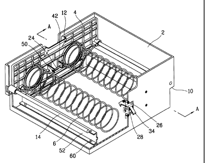
Figure 3 is a perspective view showing a media cassette for an automatic
s dispenser in accordance with the present invention, Figure 4 is a sectional
view
taken along section line A-A in Figure 3 and Figure 5 is a sectional view
showing a
width varying means of the media cassette in accordance with the present
invention.
The media cassette for an automatic dispenser includes a cassette body 2
Io having a certain interior space in which media to be dispensed is received,
a push
plate 4 installed slidably in the cassette body 2 for supporting media
received
therein, an elastic member 6 positioned between the push plate 4 and the
cassette
body 2 for urging the push plate towards a dispensing position of the media,
guide
members installed between the both side surfaces of the push plate 4 and the
is inner sides of the cassette body 2 for guiding the push plate 4 to perform
linear
movement, and a locking mechanism installed between the push plate 4 and the
cassette body 2 for locking the push plate 4.
In the cassette body 2, a width varying device which can vary the width of
the interior space in the cassette body 2 according to the size of the media
is
2o installed.
The cassette body 2 has a rectangular shape. At a front lower side of the
cassette body, an outlet port 8 for discharging stored media is formed and a
guide
line 10 which guides the media in case of receiving the media into the
automatic
dispenser is formed at both side surfaces.
2s The push plate 4 is installed in the cassette body 2 standing upright and
CA 02360253 2001-10-26
-9-
having a shape of a flat plate and has a handle 12 with which a user can hold
and
pull at the center of the upper side of the push plate.
The elastic member 6 has an end fixed on the rear surface of the push
plate 4 and another end having a coil spring fixed on the inner wall surface
of the
s cassette body 2 for pushing the push plate 4.
As shown in Figure 5, the guide members include a guide rods 14 which
are installed at the both sides of the cassette body extending in the
longitudinal
direction and guide holes 16 formed at the both sides of the push plate 4 and
respectively fixed slidably on the guide rods 14.
io Here, in each of the guide holes 16, a bushing 18 is inserted thus to help
the guide holes slide on the guide rods 14.
The locking mechanism includes a hook assembly 22 mounted through an
installing hole 20 which is formed in the center of the rear side wall of the
cassette
body 2 for locking the push plate 4 and a latching pin 24 provided at the
center of
the rear side of the push plate 4 and engageable by the hook assembly 22.
The hook assembly 22 includes a bracket 28 which is mounted in the
installing hole 20 as formed in the cassette body 2 with bolts 26, a hinge
shaft 30
transversely fixed to the bracket 28, a hook member 36 having an end protruded
to the inner side of the cassette body 2 forming a hook part 32 which is
protruded
20 outwardly from the cassette body 2 and engageable with the latching pin 24
and
another end having a locking release button part 34 for releasing locking
operation
under the condition of being rotated on the hinge shaft 30 and a return spring
38
for urging the hook member 36 to its original position on the hinge shaft 30.
Here, the locking release button part 34 of the hook member is formed to
2s be protruded outwardly of the cassette body 2 at a certain angle so that
the button
CA 02360253 2001-10-26
10-
can be pushed and operated when a door of the automatic dispenser is closed.
The latching pin 24 is axed to two mounting parts which are protruded at a
certain interval from the rear surface of the cassette body 2, and retaining
ring 50
for preventing separation of the latching pin 24 are installed at both ends of
the
s latching pin 24.
The locking mechanism overcomes the elastic force of the elastic member
6 and the push plate 4 moves inwardly in the cassette body 2 in case of
holding
and pulling the handle 12 of the push plate. At this time, the latching pin 24
is
latched by the hook part 32 of the hook member and the push plate 4 is locked.
In
~o this condition, if the door (not shown) of the automatic dispenser is
closed after the
media are stored in the cassette body 2, the rear surface of the door pushes
the
locking release button part 34, whereby the hook member rotates out of
latching
engagement with the latching pin and thereby locking of the push plate 4 is
released and the push plate 4 supports the media with certain elastic force.
is As shown in Figure 5, the width varying device includes a support panel
52 installed at each side of the cassette body 2 extending in the longitudinal
direction for respectively supporting both side surfaces of the media, first,
second
and third position determining holes 54, 56 and 58 which are formed in the
bottom
surface at both sides of the cassette body 2 at certain intervals so that the
position
20 of the support panels 52 in the transverse direction in the cassette body 2
can be
changed according to the size of the media stored and position fixing bolts 60
for
fixing the support panels 52 to the position determining holes 54, 56 and 58.
The number of the position determining holes 54, 56 and 58 can be
increased accordingly as the size of the media varies.
2s Each supporting panel 52 has a bolt hole 62 where a position fixing bolt 60
CA 02360253 2001-10-26
-11-
is installed on the surface abutted on the bottom surface of the cassette body
2.
The width varying device fixes the supporting panels 52 by selecting one
of the first, second and third position determining holes 54, 56 and 58
according to
the size of the stored media.
s Operation of the media cassette for the automatic dispenser in
accordance with the present invention with the above composition will be
described.
Figure 6 is a block diagram showing the media cassette in accordance
with the present invention.
to Firstly, in case of holding and pulling back the handle 12 of the push
plate
to secure a space for storing the media, the push plate 4 overcomes the
elastic
force of the elastic member 6 and moves inwardly in the cassette body 2. At
this
time, the push plate 4 performs linear movement along through the guide rods
14
since the guide holes 16 of the push plate 4 move along the guide rods 14 of
the
i s cassette body 2.
If the push plate 4 moves to near the rear portion of the cassette body 2,
the latching pin 24 which is installed on the push plate 4 is latched on the
hook
assembly 22 installed at the rear of the cassette body 2 and the push plate 4
is
locked.
2o In this condition, after storing the media in the cassette body 2, the
media
cassette is ready to be received into the automatic dispenser. Here, if the
door of
the automatic dispenser is closed after receiving the media cassette into the
automatic dispenser, the rear surface of the door pushes the locking release
button part 34 of the hook assembly and accordingly, the locking of the push
plate
2s is related and the media is supported elastically toward the dispensing end
due to
CA 02360253 2001-10-26
-12-
releasing of the locking of the push plate 4.
Namely, if the rear surface of the door pushes the locking release button
part 34, the hook member 36 rotates around the hinge shaft 30, whereby the
hook
part 32 is separated from the latching pin 24 and locking is released.
s In case of storing a media having a bigger size than that of the currently
stored media, the position fixing bolts 60 are tightened after moving the
supporting
panels 52 to the direction of the inside of the cassette body and aligning the
bolt
holes 62 with the third position determining hole 58. On the contrary, in case
of
storing a media having a smaller size than that of the currently stored media,
the
to position fixing bolt 60 is tightened after moving the supporting panel 52
to the
direction of the inside of the cassette body and aligning the bolt holes 62
with the
first position determining hole 54.
The media cassette in accordance with the present invention with the
above composition and operation can prevent a incorrect operation generated in
is case of receiving the cassette with a push plate of which locking is not
released by
releasing locking of the push plate by having the door push the locking
release
button if the media cassette is received and the door is closed after storing
the
media by locking the push plate with the locking mechanism and the present
invention has an advantage that its use is convenient since locking of the
push
2o plate does not need to be released by hand.
Also, the media cassette in accordance with the present invention has
another advantage that its usefulness can be widened since media of many
difference side edges can be received by having the supporting panels for
supporting the both sizes of the media movable at the both sides of the
cassette
2s body in the transverse direction.
CA 02360253 2001-10-26
-13-
As the present invention may be embodied in several forms -without
departing from the spirit or essential characteristics thereof, it should also
be
understood that the above-described embodiments are not limited by any of the
details of the foregoing description, unless otherwise specified, but rather
should
s be construed broadly within its spirit and scope as defined in the appended
claims,
and therefore all changes and modifications that fall within the meets and
bounds
of the claims, or equivalence of such meets and bounds are therefore intended
to
be embraced by the appended claims.