Note: Descriptions are shown in the official language in which they were submitted.
CA 02360406 2001-10-29
1
BUNDLE OF HOLLOW FIBRES FOR A DEVICE FOR EXTRACORPOREAL
TREATMENT OF BLOOD AND PLASMA, AND PROCESS FOR ITS
PRODUCTION
The present invention relates to a bundle of hollow fibres for a device for
treating
blood or plasma by extracorporeal circulation, and to a process for producing
a bundle of
hollow fibres constituting the semi-permeable membrane of the device.
Membrane devices for treating blood or plasma by extracorporeal circulation
are
1 o used in many different medical or paramedical applications, such as
treating renal
insufficiency by dialysis or haemofiltration, plasmapheresis and apheresis for
therapeutic
and non-therapeutic purposes, oxygenating blood, immunopurification, etc.
In general, semi-permeable membranes can be classified by their hydraulic
permeability into low flux membranes, medium flux membranes and high flux
membranes.
Hydraulic permeability describes the quantity of water that can be
ultrafiltered
through a semi-permeable membrane with a given active surface area, at a given
transmembrane pressure over a given time period. Simultaneously with the water
ultrafiltration, salts and toxins traverse the semi-permeable membrane.
Eliminating the
2 0 different solutes depends on a property of the membrane known as the
rejection rate or
transmittance (transmittance = 1 or rejection rate = 0 for solutes traversing
the membrane
with no change in concentration, rejection rate = 100% and transmittance = 0
for
completely cleared solutes). The transmittance of a particular molecule is
defined as the
ratio of the concentration of the molecule in ultrafiltered water
(ultrafiltrate) to its mean
concentration in the unfiltered fraction of the blood.
With high flux semi-permeable membranes, i.e., with a hydraulic permeability
of at
least 31 x 10-12 m3/s.Pa.m2 (15 mllh.mmHg.m2), the quantity of water extracted
from the
blood must be regulated using a water extraction controller. Devices provided
with a high
3 0 flux membrane run the risk of reverse filtration or back filtration, which
consists of
migration of a portion of the dialysis solution into the blood.
CA 02360406 2001-10-29
la
The dialysis solution, which has an electrolytic composition that is close to
that of
a normal extracellular liquid, is usually a non-sterile aqueous solution.
Before use, the
dialysis solution is normally free of solutes to be eliminated from the blood,
but can contain
foreign substances or pyrogenic substances, for example as a result of
microbial
contamination. Dialysis solution is not intended for injection into the blood
and thus does
CA 02360406 2001-10-29
2
not have the quality of an injectable liquid. With back filtration, then,
there is then a risk of
causing foreign or pyrogenic substances to enter the blood with the dialysis
solution.
As is known, back filtration can be minimised by using semi-permeable low flux
membranes with a hydraulic permeability of less than 12.5 x 10⁻¹² m3/s.Pa.m2
(6
s ml/h.mmHg.m2), or medium flux semi-permeable membranes with a permeability
of
between about 12.5 and about 31 x 10-~Z m3/s.Pa.m2 (between about 6 and about
15
ml/h.mmHg.m2). However, the reduction in hydraulic permeability is generally
accompanied by a reduction in transmittance, i.e., a reduction in the fraction
of certain
molecules that pass by convection through the pores of the membrane and which
are
t o intended to be eliminated from the blood.
Thus, one aim of the invention is to provide a device for treating blood or
plasma by
extracorporeal circulation, comprising a semi-permeable membrane with a
reduced overall
hydraulic permeability to limit the risks of reverse filtration, while
retaining satisfactory
transmittances, in particular those for toxins and proteins.
15 A further aim of the invention is to provide a device for treating blood or
plasma by
extracorporeal circulation comprising a semi-permeable membrane, the
characteristics
(hydraulic permeability, transmittances) of which can be adjusted
independently of each
other to a certain extent such that the hydraulic permeability of the membrane
is low flux,
medium flux or high flux, while the transmittances, in particular as regards
toxins and
2o proteins, are maintained at satisfactory values.
In a first aspect of the invention, these aims are achieved by a bundle of
hollow
fibres intended to constitute the semi-permeable membrane of a device for
treating blood or
plasma by extracorporeal circulation, in which:
~ the distribution of the hollow fibres in the bundle is heterogeneous; and
25 ~ the internal diameter and wall thickness of the hollow fibres located in
the zones
most dense in hollow fibres are respectively greater than the internal
diameter
and wall thickness of the hollow fibres located in the least dense zones.
Preferably, the internal diameter and wall thickness of the hollow fibres
located in
the zones least dense in hollow fibres are respectively a minimum of 180
microns and 40
30 microns.
CA 02360406 2001-10-29
J
In a variation of the invention:
~ the heterogeneity of the distribution of the hollow fibres in the bundle
corresponds to a higher density of hollow fibres around at least a portion of
the
periphery of the bundle compared with a density of hollow fibres at the centre
of the bundle; and
~ the internal diameter and wall thickness of the hollow fibres located at the
periphery of the bundle are respectively greater than the internal diameter
and
wall thickness of the hollow fibres located at the centre of the bundle.
In a second aspect of the present invention, the above aims are achieved by a
bundle
of hollow fibres intended to constitute the semi-permeable membrane of a
device for
treating blood or plasma by extracorporeal circulation, in which:
~ the hydraulic permeability of the hollow fibres in the bundle is
heterogeneous; and
~ the ratio of the highest hydraulic permeability measured on some hollow
fibres of the
bundle to the lowest hydraulic permeability measured on other hollow fibres of
the
t 5 same bundle is at least about 5.
In a variation of the invention, the heterogeneity of the hydraulic
permeability in the
bundle corresponds to a higher hydraulic permeability around at least a
portion of the
periphery of the bundle compared with a hydraulic permeability of the bundle
fibres, such
that the ratio of the highest hydraulic permeability measured at the periphery
of the bundle
2o to the lowest hydraulic permeability measured at the centre of the bundle
is at least about
5
In a further variation of the invention, the heterogeneity of the hydraulic
permeability is associated with a heterogeneity of the distribution of the
hollow fibres in
the bundle, the hydraulic permeability being higher in the zones most dense in
hollow fibres
25 and lower in the zones least dense in hollow fibres.
Advantageously, the internal diameter and wall thickness of the hollow fibres
located in the zones most dense in hollow fibres are respectively greater than
the internal
diameter and wall thickness of the hollow fibres located in the zones least
dense in hollow
fibres. Advantageously again, the internal diameter and wall thickness of the
hollow fibres
CA 02360406 2001-10-29
4
located in the zones least dense in hollow fibres are respectively a minimum
of 180 microns
and 40 microns.
In one embodiment of the invention, the overall hydraulic permeability of the
bundle of hollow fibres is in the range 10 x 10-2 to 312 x 10-2 m3/s.Pa.m2 (5
to
150 m1/h.mmHg.m2), the lowest hydraulic permeability measured at the centre of
the
bundle is less than 17 x 10-2 m3/s.Pa.m~ (8 ml/h.mmHg.m2) and the highest
hydraulic
permeability measured at the periphery of the bundle is more than 42 x 10-~2
m3/s.Pa.m2
(20 ml/h.mmHg.m2).
In a further embodiment, the overall hydraulic permeability of the bundle of
hollow
~o fibres is in the range 42 x 10-2 to 146 x 10-2 m3/s.Pa.m2 (20 to 70
ml/h.mmHg.mZ), the
lowest hydraulic permeability measured at the centre of the bundle is less
than
17 x 10-2 m3/s.Pa.m2 (8 ml/h.mmHg.mz), the highest hydraulic permeability
measured at
the periphery of the bundle is more than 83 x 10-2 m3/s.Pa.m2 (40
ml/h.mmHg.m2) and the
ratio of the highest hydraulic permeability measured at the periphery of the
bundle to the
lowest hydraulic permeability measured at the centre of the bundle is at least
10.
Within the context of the present invention, the overall hydraulic
permeability Lp
of the bundle is conventionally obtained by measuring the filtration time t of
a volume V of
water at a mean transmembrane pressure P of the order of 50 to 500 mmHg
tluough a
surface area S of membrane at a given temperature (see European standard EN
12.83). The
2o hydraulic permeability Lp is expressed in m3/s.Pa.mZ or ml/h.mmHg.m2 and
corresponds to
formula (I):
Lp = V/(tPS) (I) ,
To evaluate the heterogeneity of the hydraulic permeability of hollow fibres
inside a
bundle, within the context of the present invention a method has been
developed for
measuring the hydraulic permeability of a sub-group of hollow fibres of the
bundle, the
number of hollow fibres in the evaluated sub-group being substantially the
same for each
measurement. The hydraulic permeability of a sub-group of hollow fibres will
be termed
the ''local hydraulic permeability Lpi" in the description. In general, the
method for
measuring the local hydraulic permeability Lpi of a sub-group of hollow fibres
of a bundle
of hollow fibres mounted in a tubular casing comprising a lateral opening at
one of its ends,
CA 02360406 2001-10-29
the bundle of hollow fibres being fixed in the casing by an adhesive seal at
each of its ends,
and the adhesive seals having been cut perpendicular to a longitudinal axis of
the bundle to
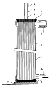
open the fibres, comprises the principal steps defined in Claiin 26 below. The
conditions
for this measurement are diagrammatically shown in the accompanying Figure 1
and are
5 described in detail below. The local hydraulic permeability Lpi measurements
are
preferably carned out on a ready-to-use hollow fibre device for the treatment
of blood or
plasma by extracorporeal circulation, i.e. after assembling the various
components of the
hollow fibre device, in particular by mounting bundle 1 of hollow fibres in a
tubular casing 2
comprising, at each of its ends, a lateral opening 5 and 6 (inlet/outlet
channel) and by setting
~ 0 seals 3 and 4, after having separated the hollow fibres from each other at
their ends, for
example by riffling or brushing their ends, manually or with a stream of air.
This allows the
ends of hollow fibres that have stuck together to be separated and eliminates
the risk of
leakage into the seal. As is well known, the sealing operation consists of
securing the two
ends of the bundle of hollow fibres by adhesive bonding using a seal in which
a portion of
I S the length of the fibres is embedded, the ends of the fibres being left
open. Then the
adhesive seals, in which the open ends of the hollow fibres are secured by
adhesive and
substantially uniformly distributed, are cut. To measure the local hydraulic
permeability,
casing 2 containing the bundle of hollow fibres is placed in a vertical
position, and a seal is
produced at the lower end of the casing (and as a result the lower cut surface
of the bundle)
2o by pressing it on a plate 11 to ensure a seal, for example a plate of a
flexible plastics
material such as a silicone. A liquid, for example water or a dialysis liquid,
is then passed at
a flow rate of 80 ml/min, for example, through the lower lateral opening 6
while the upper
lateral opening 5 is closed. A calibrated tube 12, in the vertical position,
is applied to a
portion of the upper cut surface of the bundle to measure the local flow rate
at the upper
25 end of the casing. To carry out the measurement, calibrated tube 12 is
firmly applied
against the portion of the upper cut surface to be evaluated (in the figure,
against the centre
of the bundle of hollow fibres), to form an intimate connection between the
upper cut
surface and the calibrated tube 12. A flow of liquid is applied via lower
lateral opening 6 of
casing 2 and the time t that the liquid takes to pass from a given first
graduation 13 to a
3o second given graduation 14 provided on calibrated tube 12 is measured. From
the local
CA 02360406 2001-10-29
6
measured flow rate (corresponding to the defined volume V of tube 12 between
the two
graduations 13, 14 related to the time t for the liquid to pass from
graduation 13 to
graduation 14) and the known values of the transmembrane pressure P and the
surface area
Si of the hollow fibres in the sub-group on which the local flow rate is being
measured, the
local hydraulic permeability Lpi is measured using the following formula (II):
Lpi = V/(tPSi) (II).
The dimensions of the calibrated tube 12 are not critical. They are suitable
to allow
local measurement of the flow rate. Thus the diameter of calibrated tube 12
can be 3.2 cm
and its height can be of the order of 50 cm.
It should be noted that the local hydraulic permeability measured with the
above
method corresponds in fact to back filtration (passage of liquid from the
dialysate
compartment to the blood compartment, as conventionally defined, in particular
via the
insides of the hollow fibres), but other tests carried out by the Applicant
have shown that
the value of the hydraulic permeability of the hollow fibres does not depend
on the
i 5 direction of passage of the liquid.
By carrying out local hydraulic permeability measurements over the whole of
the
upper cut surface of the bundle of hollow fibres, the local hydraulic
permeability can be
mapped to show the variation with measurement zone. In this respect, it should
be noted
that the number of hollow fibres evaluated during each local hydraulic
permeability
2o measurement is substantially constant. The operation of separating the
hollow fibres from
each other at their ends prior to sealing homogenises the hollow fibre density
at the ends of
the bundle.
In accordance with the present invention, the devices for treating blood or
plasma
by extracorporeal circulation contain a bundle composed of an assembly of
hollow fibres
25 that differ from each other by their hydraulic permeability, certain hollow
fibres being low
flux while other hollow fibres are high flux. Overall, devices according to
the present
invention have the advantage of being capable of being high flux, medium flux
or low flux
depending on the local hydraulic penneabilities of the hollow fibres in the
bundle.
CA 02360406 2001-10-29
7
The devices of the invention have the further advantage of having higher
transmittance values than those obtained with conventional devices with an
equivalent
hydraulic permeability.
Thus, in the present invention, the devices can have a transmittance for
cytochrome
C of about 0.1 to about 0.6 (measured under the conditions specified in
standard EN 12.83)
with overall hydraulic permeability values of 20 x 10-~Z to 312 x 10-2
m3/s.Pa.m2 (10 to
150 ml/h.mmHg.mZ)
In a variation of the invention, to produce the hollow fibre devices of the
invention,
hollow fibres consisting mainly of polyaiylsulphone are selected. Preferably,
they contain
1 o repeating units with formula (I) or (II) below:
CH3
C p- O S02- ~ (~)
o-~ O ~ n
I
CHs
O -~ 502 -
n
The polyarylsulphone with formula (I), the chain of which contains alkyl
radicals,
l5 in particular methyl radicals, is termed a polysulphone. The
polyaiylsulphone with
formula (II), which simply contains aryl radicals connected together by an
ether or a
sulphone group, is termed polyethersulphone.
The invention also pertains to a process for producing a bundle of hollow
fibres
consisting mainly of polarylsulphone, useful as a semi-permeable membrane in a
device for
2o treating blood or plasma by extracorporeal circulation, the process
comprising the following
steps:
(a) preparing a bundle of hollow fibres with a heterogeneous distribution
of fibres within the bundle insofar as the density of the hollow fibres .is
higher in certain zones of the bundle than in other zones;
CA 02360406 2001-10-29
g
(b) mounting the bundle of hollow fibres in a tubular casing comprising
two axial openings;
(c) causing a hot, dry gas that is chemically inert towards the hollow
fibres, preferably hot, dry air, to circulate through the bundle of hollow
fibres, not held at its ends, at a temperature and flow rate that are suitable
to
cause geometrical heterogeneity of the hollow fibres in the bundle as regards
the internal diameter and wall thickness of the hollow fibres;
(d) stopping the hot, dry gas from circulating when the geometrical
heterogeneity of the hollow fibres has been obtained.
Adjusting the operating conditions of steps a) and c) affects the
characteristics of
devices for extracorporeal treatment of blood, in particular the hydraulic
permeabilities.
The term "hot, dry gas" as used in the context of the present invention means
a hot
gas with a relative humidity that does not exceed 10% at the temperature at
which the gas is
used. Preferably, the temperature of the hot, dry gas at the inlet to the
bundle of hollow
fibres is 75°C to 130°C, more preferably 90°C to
120°C.
Preferably, the flow rate of the hot, dry gas at the inlet to the bundle of
hollow
fibres is 2 to 5 m3 per hour.
Preferably, the duration of step (c), consisting of circulating a hot, dry gas
tluough
the bundle of hollow fibres, is of the order of 1 to 4 hours.
2o Preferably, circulation of the hot, dry gas is stopped when the temperature
of the
gas at the outlet from the tubular casing is substantially equal to the
temperature of the gas
at the inlet to the tubular casing.
The invention also concerns a bundle of hollow fibres resulting from carrying
out
the production process described above.
Further characteristics and advantages of the invention will become apparent
from
the detailed description below, concerning variations and embodiments of the
present
invention.
Reference should also be made to the accompanying drawings, in which:
~ Figure 1 shows a diagrammatic view in longitudinal section of the device for
;o measuring local hydraulic permeability in accordance with the invention;
CA 02360406 2001-10-29
9
~ Figure 2 shows a partial diagrammatic perspective view of a fibre guiding
device;
~ Figure 3 shows a perspective diagrammatic view of two carriages of the fibre
guiding device that guide the hollow fibres into a semi-cylindrical trough;
~ Figure 4 shows an example of the variation with time of the amplitude of the
reciprocating motion of the hollow-fibre guide carriages;
~ Figure 5 shows a diagrammatic view in transverse section of a bundle of
hollow
fibres after a fibre guiding step carried out in the manner described for
Figure 4;
~ Figures 6a, 6b, 6c and 6d show the influence of the conditions of
circulation of
hot, dry air through the bundle of hollow fibres on the hydraulic permeability
of
i o the hollow fibres;
~ Figure 7 shows the correlation between the length of the hollow fibre after
circulating hot, dry air and its hydraulic permeability.
To provide a detailed illustration of the invention, the production of a
pauticular
type of device for extracorporeal treatment of blood in accordance with the
present
invention will now be described.
1. Production of hollow fibre
A polymer solution for extrusion is prepared that contains:
~ 14% by weight of polyarylsulphone, in particular a polyethersulphone (with a
weight average molecular weight Mw of 70000 Daltons) miscible with N-
2o methylpyrrolidone (NMP);
~ 5% by weight of a mixture of polyvinylpyrrolidone (PVP) of the K30 and K90
type, miscible with water and NMP;
~ 1% by weight of water;
~ 80% by weight of NMP.
Mixing is carned out at high temperature, of the order of 80-90°C,
applying high
shear forces. The solution is then cooled, preferably to 20°C.
To obtain a hollow fibre, the above polymer solution is extruded through a die
comprising two concentric circular openings, an external annular opening to
extrude the
polymer solution and an internal central opening for passage of the hollow-
fibre centring
3o and precipitating liquid. The external and internal diameters of the
annular opening of the
CA 02360406 2001-10-29
die are respectively 500 microns and 350 microns, and the diameter of the
internal central
opening is 170 microns.
The composition of the hollow-fibre centring and precipitating liquid in this
example is a homogeneous mixture of 44% by weight of NMP, 55% by weight of
water and
1 % by weight of PVP.
Under the conditions of this example, a hollow fibre is formed with an
internal
diameter of 215 ~.m and a wall thickness of 50 p.m.
The hollow fibre is then carefully washed with water that is free of
pyrogenous
elements by passing it through a plurality of baths without stretching it.
t o 2. Production of bundle of hollow fibres
In accordance with the invention, when extrusion is complete, after
precipitation
and washing the hollow fibres, a bundle of hollow fibres is prepared that is
substantially
rectilinear with a heterogeneous distribution of fibres inside the bundle
whereby the density
of the hollow fibres is higher at the periphery of the bundle and lower at the
centre of the
bundle. The chemical nature of the hollow fibres in this example is identical
throughout the
bundle.
In this example, preparation of the fibre bundle comprises a fibre guiding
step
carried out using a fibre guiding device (shown diagrammatically in the
accompanying
Figures 2 and 3). Fibre guiding is an operation that consists of structuring
the fibre bundle
2o and results in a criss-crossed arrangement of fibres. To this end, the
fibre-guiding device
comprises:
~ a drum 20 with a winding surface 21 with a regular polygonal cross section
that
can be rotated about its axis of symmetry 22, each side of the winding surface
21 of drum 20 being provided with a semi-cylindrical trough 23, the axes 24 of
the semi-cylindrical troughs 23, which are aligned about the drum 20, being
coplanar; and
~ at least one carriage 30 (in this case two carriages 30) carrying at least
one set of
guide rollers (not shown). located a certain distance from the drum 20, to
guide
and supply at least one hollow fibre 40 (or at least one strand of hollow
fibres)
3o to the semi-cylindrical troughs 23, each carriage 30 being movable in a
CA 02360406 2001-10-29
reciprocating motion perpendicular to the plane containing the axes 24 of
troughs 23, with a variable amplitude not exceeding the diameter of the semi-
cylindrical troughs.
The fibre guiding step consists of winding at least one hollow fibre 40 onto
the
s drum 20, which drum is rotated about its axis of symmetry 22, the hollow
fibre being
supplied and guided by the guide rollers on at least one carriage 30 to semi-
cylindrical
troughs 23 turning with the drum 20, to fill the troughs 23. In this example,
the
reciprocating motion of the two carnages 30 is in phase opposition and the
reciprocating
motion of each carriage 30 varies with time as shown in Figure 4 as the
troughs 23 are filled,
i o leading to the formation of bundles of hollow fibres:
( 1 ) initially, to fill the bottom of the semi-cylindrical troughs 23, the
reciprocating motion amplitude is small;
(2) then the reciprocating motion amplitude varies regularly, increasing
to reach a plateau corresponding to a value less than the diameter of the
15 semi-cylindrical troughs 23;
(3) then the reciprocating motion amplitude is kept constant for a certain
period; and
(4) finally, the reciprocating motion amplitude varies regularly, reducing
to a very small value.
20 Further, during steps (1) to (4) above, the speed of rotation of drum 20 is
substantially constant and the speed of displacement of each carnage 30 is
substantially
constant.
Preferably, the fibres are arranged into a bundle immediately after their
production.
Between the extrusion device and the fibre-guiding device, they are kept under
tension
25 without stretching them. They are wound onto drum 20 at a constant
circumferential speed
(circumferential speed of drum 20 in rotation about its axis of symmetry 22)
in the range 20
to 80 metres/minute. As indicated above, semi-cylindrical troughs 23
corresponding to the
number of bundles to be manufactured are fixed to the winding surface 21 of
drum 20. In
this example, the diameter of the troughs 23 is slightly larger than the
diameter of the
3o bundles of hollow fibres before they are subjected to a circulation of hot,
dry air, while the
CA 02360406 2001-10-29
12
length of the troughs is slightly less than that of the bundles of hollow
fibres. In this
example, the trough diameter is 45 mm with a length of 280 mm. Twelve semi-
cylindrical
troughs 23 are mounted on the drum 20.
In this example, the hollow fibres leaving the extrusion step are distributed
into two
groups of fibres using fixed separating rollers (not shown), each group of
fibres beiizg
separately guided by a set of integral movable rollers carried by each of the
respective
carriages 30. The two groups of hollow fibres finally meet on the troughs 23
whereupon
they are wound around the drum 20. As indicated above, the two carriages 30
are displaced
in a reciprocating motion in phase opposition, with a variable amplitude, in
this case from 0
to to 40 mm. Advantageously, each carriage 30 carries out an odd, non-integer
number of
movements in one direction per turn of the drum 20 that varies from 3 to 15,
preferably 7.1
movements in one direction.
The displacement of the two carriages 30 that guide the fibres 40 towards the
troughs 23 with a constant circumferential speed and a variable amplitude
influences the
structure of the bundle of hollow fibres. The density of the fibres disposed
in the trough is
inversely proportional to the amplitude of the displacement of the carriages
30: the smaller
the displacement amplitude, the higher the density of the fibres placed in the
troughs 23.
The fibre-guiding step contributes towards heterogeneous distribution of the
hollow fibres
with a higher fibre density in certain parts of the bundle. In this case, the
bundles of hollow
2o fibres, after they have satisfied the conditions regarding the time
variation of the amplitude
of the reciprocating motion of the guide carriages 30 indicated in Figure 4,
have a higher
density at the periphery compared with the density at the centre (see Figure
5). Further,
each bundle. comprises two longitudinal peripheral and opposed zones where the
densities
in hollow fibres are at their highest: these two zones correspond to the start
and finish of
filling of the troughs 23.
Clearly, the reciprocating motion amplitude of carriages 30 can be varied with
time
in a different way, and a different distribution of hollow fibres from that
described above
thus be produced, the zones most dense in hollow fibres then not necessarily
being at the
periphery of the bundle.
CA 02360406 2001-10-29
13
When the predefined number of hollow fibres per trough 23 has been reached,
drum
20 is stopped from rotating, troughs 23 are closed with a semi-cylindrical
cover (not
shown) and the fibres between each trough 23 are cut.
In this example, each bundle of hollow fibres is then transferred into a
tubular casing
comprising two axial openings and two lateral openings.
After equalising the length of the hollow fibres for each bundle, the
operations
required to dry the bundles of fibres are carried out. If necessary, firstly,
the liquid present
in the hollow fibres is eliminated, preferably by centrifuging.
Then, in accordance with the invention, hot, dry air is passed through the
bundles of
~ o hollow fibres that are not held at their ends, the hot, dry air entering
via one axial opening iil
the casing and leaving via the other axial opening in the casing, the two
lateral openings in
the casing being closed.
The hot, dry air is circulated under the temperature, flow rate and duration
conditions described above, to cause a geometrical heterogeneity of the hollow
fibres in the
t 5 bundle (i.e., differences in the internal diameter and wall thickness of
the fibres) and a
heterogeneity in the density of the hollow fibres in the bundle.
Advantageously, the hot, dry air is injected via one of the axial openings of
the
casing with the speed of the circulation front homogeneous over the whole of
this opening,
under turbulent flux.
20 The hot, dry air introduced into the casing encounters the zones most dense
in
hollow fibres (at the periphery of the bundle) and preferentially passes along
the less dense
zones (in particular at the centre of the bundle). Further, circulating hot
air in the casuig
tends to displace and constrain the hollow fibres towards the periphery of the
bundle,
against the walls of the casing. This drying step, therefore, also contributes
to
25 heterogeneity in the distribution of the hollow fibres in the bundle.
Further, because of the preferential passage of the hot air along the central
portion
of the bundle, the fibres of the interior of the bundle shrink more (length,
internal and
external diameters and thickness) than those at the periphery of the bundle.
With such a bundle of hollow fibres, a device can be produced to treat blood
or
3o plasma with reduced risks of reverse filtration, an overall hydraulic
permeability that can be
CA 02360406 2001-10-29
14
adjusted to requirements and with transmittances that are higher than those of
a
conventional device with a similar hydraulic permeability.
Further, with such a bundle, a device can be produced for treating blood or
plasma
with characteristics (hydraulic permeability, transmittances) that can be
independently
adjusted to a certain extent so that the hydraulic permeability of the
membrane is low flux,
medium flux or high flux, while the transmittances, in particular those for
toxins and
proteins, are maintained at values that are higher than those of a
conventional device with a
similar hydraulic permeability.
The last steps necessary for finishing the manufacture of a device for
treating blood
~o or plasma by extracorporeal circulation in accordance with the invention
after stopping the
circulation of the hot, dry air as soon as the bundle of hollow fibres is
sufficiently dry to
allow it to be sealed, are conventional. The principal steps are:
~ homogenising the distribution of the fibres, limited to the ends of the
bundle;
~ sealing, consisting of securing the two ends of the bundle of hollow fibres
by
adhesion using a seal in which a portion of the length of the fibres is
embedded,
the ends of the fibres being left open;
~ cutting the ends of the bundle;
~ closing the tubular casing at its two ends with caps;
~ sterilising the medical device.
2o EXAMPLES 1 TO 5
Dialysers comprising about 8000 hollow polyethersulphone fibres were produced
and assembled as in the above detailed description.
Only the conditions for circulating the hot, dry air differed between the
examples.
The table below summarises these conditions.
CA 02360406 2001-10-29
Example Air flow rate Temperature of hot,
(m3/h) dry
air at inlet into
tubular
casing, C
Comparative example 2 60
1
2 2 110
3 2 120
q 4 110
120
From the results for the measurements of local permeability Lpi, four maps
were
established by mathematical regression: see Figures 6a, 6b, 6c and 6d, which
correspond to
Examples 2, 3, 4 and 5, respectively. In Figures 6a, 6b, 6c and 6d:
5 ~ the axes of the abscissas and ordinates, graduated from -50 mm to +50 rnm,
represent two directions that are perpendicular to each other, of one of the
cut
surfaces of the ends of the bundle of hollow fibres;
~ each curve, closed or otherwise, marked in dotted lines or as a solid line,
represents points with the same local hydraulic permeability Lpi, expressed in
1 o ml/h.mmHg.m2;
the central curve, shown in dotted lines, represents points with a local
hydraulic
permeability Lpi of 0 ml/h.mmHg.m2;
~ the difference between two successive curves is 10 ml/h.mmHg.m2;
~ the key given with each figure notes successive values of the local
hydraulic
~ 5 permeability Lpi at each curve starting from the central curve.
Figures 6a, 6b, 6c and 6d demonstrate that the local hydraulic permeabilities
Lpi are
higher at the periphery of the bundle than at the centre of the bundle.
The table below also shows the influence of the conditions for circulating
hot, dry
air on the overall and local hydraulic permeabilities, Lpi, measured before
sterilisation.
CA 02360406 2001-10-29
1G
Hydraulic
permeability
(mUh.mmHg.m2)
Example n Overall Minimum at Maximum at Max/min
bundle centrebundle peripheryratio
1 (comparative)200 200 200 1
2 30 1.5 80 53
3 25 0.9 63 70
4 23 4.1 98 24
S 18 1.5 46 30
The table below shows the dimensions of certain hollow fibres before and after
circulating hot, dry air through the bundle of Example 2. The fibre dimensions
were
measured using an optical microscope and the results shown below in the table
correspond
to an average of measurements over 36 fibres.
Internal diameterExternal diameterWall thickness
(Nnl) (l~nl) (I~m)
Before circulating215 315 50
hot,
dry air
After circulating
hot,
dry air:
hollow fibres 213.7 313.6 49.9
at
periphery of bundle
hollow fibres 205.7 299.1 46.7
at
centre of bundle
EXAMPLES 6 TO 10
Dialysers comprising about 8000 hollow polyethersulphone fibres were produced
and assembled as in the above detailed description.
CA 02360406 2001-10-29
17
The conditions for producing the dialysers were substantially similar, with
the
exception of the conditions for circulating the hot, diy air, which differed
from one example
to another.
The table below shows the conditions and the results of measurements of the
overall hydraulic permeability.
Example Hot air flow Temperature Overall hydraulic
n rate of hot, permeability
(m3/h) dry air at inlet(ml/h.mmHg.mz)
(C)
6 ~ 2, then 1 85-90 37
7 ~ 4, then 2 85-90 51
8 ~ 4, then 2 75-80 54
9 ~ 2 90 33
~ 1 90 29
EXAMPLES 11 TO 29
Dialysers comprising about 8000 hollow polyethersulphone fibres were produced
and assembled as described in the above detailed description.
1 o The conditions for producing the dialysers were substantially similar with
the
exception of the hot, dry air circulation conditions, which differed between
examples.
The table below shows the conditions and the results of measurements of the
overall hydraulic permeability Lp and cytochrome C transmittance (Tr), and
measurements
of the length (L) of the hollow fibres, maximum and minimum, after circulating
hot, dry air.
~ 5 The transmittance measurement conditions were: a starting concentration of
cytochrome C
of 0.05 g/1, a blood flow rate of about 400 ml/min and an ultrafiltration flow
rate of about 80
ml/min. The maximum length, Lmax, and the minimum length, L min, corresponded
to the
length of the longest fibre and shortest fibre in the bundle respectively. The
longest fibre
was located at the periphery of the bundle, while the shortest was located at
the centre of
2o the bundle.
CA 02360406 2001-10-29
Example Air TemperatureLp Tr for Lmax L min Difference
no. flow of hot, (ml/h.mmcytochrome(mm) (mm) between
rate dry Hg.mm2) C Lmax and
(m3/h)air at Lmin
inlet (nun)
to
tubular
casing,
C
11 4.5 102 46.9 n.m. 269.6 268.3 1.3
12 4.5 97.5 55.8 n.m. 270.4 269.4 1.0
13 4.0 97.5 48.7 n.m. 270.2 269.5 0.7
14 4.5 100 42.6 0.23 269.8 268.9 0.9
15 4.5 100 34.1 0.22 269.8 268.5 1.3
16 4.8 93 58.4 0.36 270.2 269.5 0.7
17 4.8 93 63.3 0.39 271.0 269.5 1.5
18 4.8 93 53.2 0.37 270.1 269.3 0.8
19 4.8 93 47.0 0.36 270.1 269.3 0.8
20 4.8 93 46.7 0.34 270.3 269.4 0.9
21 2 105 45.5 0.47 270.3 267.3 3.0
22 2 105 41.8 0.47 270.1 267.4 2.7
23 2 105 44.5 0.47 270.6 267.2 3.4
24 2 105 35.7 0.41 270.2 267.0 3.2
25 4 109 27.3 0.46 269.7 267.7 2.0
26 4 109 27.2 0.52 269.1 267.1 2.0
27 4 109 24.8 0.48 269.2 267.4 1.8
28 4 109 24.9 0.52 269.1 267.2 1.9
29 4.8 93 68.8 n.m. 269.9 269.3 0.6
n.m. means: not measured.
Figure 7 illustrates the relationship between the mean fibre length of the
bundle after
circulating hot, dry air (along the abscissa) and the overall hydraulic
permeability, Lp, of
the bundle (up the ordinate), established from Examples 11 to 29.
CA 02360406 2001-10-29
19
The mean fibre length corresponds to the mean of values Lmax and Lmin given
above.
Figure 7 shows a correlation between this mean fibre length and the overall
hydraulic permeability of the bundle.