Note: Descriptions are shown in the official language in which they were submitted.
CA 02360595 2003-11-06
63751-295
- 1 -
HYBRID FILM TYPE SENSOR
FIELD OF THE INVENTION
The invention is directed toward a sensor with
thick or thin film electrodes on a non-conductive substrate.
BACKGROUND OF THE INVENTION
Film based techniques have been investigated for a
wide variety of sensors. While solid-state gas sensors have
the advantage of being able to operate at elevated
temperatures, they also have the disadvantages of slow
l0 response and recovery time and a high internal operating
temperature. Substantial development work is yet to be done
before this type of sensor is applicable for use in battery-
powered instruments.
A Nafiori -coated metal oxide pH sensor with
sputtered iridium oxide sensing and silver/silver chloride
reference electrodes on alumina ceramic substrates is known.
Nafion was used as a cation-selective ionomer coating in
order to decrease the oxidation-reduction error generally
affecting the performance of metal oxide pH electrodes.
Nafion has also been used as polymer-electrolyte for a thin-
film CO sensor with macro-sized, sputtered Pt sensing and
counter electrodes and a smaller, sputtered Au electrode as
reference electrode. A 5 wt% n-propyl alcohol solution of
Nafion
CA 02360595 2003-11-06
63751-295
-2-
(DuPont;~ 1100 EV1~ is used to form the polymer electrolyte film over the
electrodes
by casting. The polymer is washed and protonated in aqueous sulfuric acid
prior to
casting: The reported lifetime of this sensor is reported to be less than one
month.
During this time, the CO oxidation current decreases steadily down to a few
percent of its original value without any period of stable measurement signal.
The
lifetime of the device may be extended up to three years by laminating the
polymer
electrolyte layer with a cast perfluorocycloether-polymer film in order to
keep the
CO permeability coefficient through Nafion constant; theoretical calculations
showed that the drift rate of the signal could be significantly reduced under
these
conditions.
A description of typical state-of the-art hydrated solid polymer electrolyte
or
ionomer sensors and sensor cells is ~ described by Kosek et al. U.S. Patent
5,527,446; LaConti and Grifflth, U.S. Patent 4,820,386; Shen et al., U.S.
Patent
5,573,fi48; and, Stetter and Pan, U.S. Patent 5,331,310. These sensor cells,
based on hydrated solid polymer electrolyte or ionomer technology, have
several
advantages over conventional electrochemical sensor cells. ~ The catalytic
electrodes are bonded directly to both sides of a proton conducting solid
polymer
ionomer membrane providing a stable electrode to electrolyte interface. One
side
of the electrolyte membrane is flooded with distilled water, making the sensor
cell
self humidifying and independent of external humidity. Since no corrosive
acids or
bases are used in the sensor cell, a lifetime of over 10 years has. been
demonstrated for solid polymer ionomer sensor cells. Finally, the sensor cells
are
easy to maintain, and so are ideal for use in remote, unattended environments.
Regular addition of water to the reservoir in the sensor housing every several
months and monthly calibration checks are the only requirements.
A disadvantage of the state-of the-art sensors described above is that the
signal-to-noise ratio may not be conducive to detection of very low
concentrations
(parts per billion, ppb) of important environmental and biomedical gases and
vapors. Also, response time may be relatively slow, and reproducibility
between
*Trade-mark
CA 02360595 2003-11-06
63751-295
-3-
sensors and sensor cells may be difficult to achieve. Also, they arse
relatively
Recently, miniaturized thick- and thin-film type sensors have been
developed where the solid ionomer membrane acts as a conduit between the gas
to be detected (sample gas) and the sensing electrode. The
sample gas permeates through the membrane itself where a 3-phase contact area
is established. A disadvantage with this configuration is that the solid
ionomer
membrane water content may control the gas permeation rate as well as proton
conductivity. As the humidity increases, the membrane water content increases.
This causes an increase in the gas diffusion rate as well as proton
conductivity and
sensor signal response. The best method of controlling or fixing the water
content
of the membrane is to have a water reservoir on the back side of the membrane,
directly opposite to where the film type electrodes and non-conductive
supportive.
substrate are located. Unfortunately in the above configuration the back side
of the
membrane is required to be free of liquid so that the sample gas can diffuse
through the membrane to the sensing electrode.
Some embodiments of the present invention overcome the limitations of the
state-of-the-art in miniaturized electrochemical sensors stated above by
uniquely
combining an advanced solid polymer ionomer membrane configuration with a film
type electrode on a non-conductive supportive substrate. The substrate has
diffusion openings or holes having a known area which permit easy access of
the
sample gas to a sensing electrode contact area. The sensor configuration
provides a three phase contact area which serves as an interface for the
membrane, the electrodes, and the gas being detected. This design utilizes the
precision of solid-state device fabrication techniques to yield inexpensive,
low
maintenance, highly sensitive, rapidly responsive, and reproducible sensor
devices
for environmental, industrial, and biomedical monitoring.
63751-295
CA 02360595 2004-05-06
- 4 -
SUMMARY OF THE INVENTION
In one aspect, the invention provides an apparatus
for detecting gases comprising: a substrate; a sensing
electrode, said sensing electrode in contact with said
substrate; an opening in the substrate proximate to said
sensing electrode for controlling a gas flow; and a gas
diffusion membrane being of electrolytic material in contact
with said sensing electrode and placed within said opening and
between the gases to be detected and said sensing electrode.
Embodiments of the invention are directed toward a
controllable and reproducible gas sensor configuration
having a three-phase contact area, whereby the sample gas
diffuses to the sensing electrode and membrane through
openings, holes or slits that extend through the non-
conductive supportive substrate.
Further embodiments of the invention are directed
toward a gas sensor where the gas diffusion process is
decoupled from the proton conduction process. The gas
diffusion is controlled only by through openings of known
area in the substrate or in the substrate and an additional
rate limiting gas diffusion barrier film, eg: polyethlene,
while proton conduction takes place only through an
electrolyte layer, e.g., a Nafion~ membrane.
Some embodiments of the invention are also
directed toward utilizing a method of mass producing film
type gas sensors by stacking a number of component layers to
form a series of adjacent sensors which are subsequently
separated into individual sensors.
Another embodiment of the invention is directed
toward a gas sensor utilized in conjunction with a gas
sensor control circuit.
CA 02360595 2003-11-06
63751-295
- 4a -
In one embodiment of the invention, a gas sensor
is utilized in a gas sensing instrument.
BRIEF DESCRIPTION OF THE DRAWINGS
Figure 1 shows a schematic top view of the non-
conductive supportive substrate.
Figure 2 shows a film type electrochemical sensor
cell with Pt/Air (Oz) reference.
Figure 3 shows a film type electrochemical sensor
cell with a polymeric gas-diffusion layer over the sensing
electrode membrane.
Figure 4a shows a top view of a thick-film type
electrochemical sensor cell..
Figure 4b shows a cross-section A-A'.
CA 02360595 2001-07-18
WO 01/36956 PCT/US00/31660
-5-
Figure 4c shows a cross-sectional view of sensor cell assembly.
Figure 5 shows a gas sensor control circuit.
Figure 6 shows a gas sensor utilized in a gas sensing instrument.
DETAILED DESCRIPTION OF THE INVENTION
Figure 1 shows the top view of a ceramic film type substrate (1) (e.g.,
alumina) having holes (2) uniformly distributed in parallel rows. The distance
between the holes in the parallel rows and the distance between the rows
determine the dimensions ofthe sensor. The holes are ideally punched in a
single
step, while the alumina plate is still soft, in the "green" stage of substrate
fabrication, prior to high-temperature sintering. Other techniques to create
the
holes include laser ablation or use of soluble fillers.
Using screen printing or lithographic techniques, conducting leads (3) and
thick- and thin-film electrodes are formed on the non-conductive substrate (1)
for
multiple electrodes. A typical sensor design utilizing this method is shown in
Figure 2, which has a single reference electrode (4) (e.g., Pt/Air (02)
electrode)
and a Pt counter electrode (5). The contact for the sensing electrode (6) is a
ring
concentric to the hole. This ring can be made of smooth, rough or platinized
platinum. Some platinization may provide better contact. Simultaneous
platinization of electrodes can be performed by customized electrolytic
plating on
properly masked multi-sensor plates.
The sensing or working electrode (7) may be a disc of Teflon~-bonded or
Nafion-bonded platinum or other electrocatalyst. A number of discs are
deposited
on an ionomer film, such as Nafion electrolyte membrane (8) at uniform
distances
from each other, for instance, by decal transfer, silk printing, spray
painting, artist
brush lettering, or by any approach which lends itself to uniform deposition
of a
design on a transfer substrate without waste. The discs' distances from center
to
center are the same as for the holes of Figure 1. The diameter of the sensing
or
CA 02360595 2001-07-18
WO 01/36956 PCT/US00/31660
-6-
working electrode disc is somewhat larger than the diameter of the hole in
Figure 1
to allow for contact between the disc and the sensing electrode support ring
of
Figure 2. Instead of a single large hole per sensor of Figure 1 (which
requires the
use of the substrate to control diffusion of the analyte), a series of smaller
openings
may be used, with small enough diameters to control diffusion independently of
the
analyte flow. The areas of the openings are chosen so as to control diffusion
of the
sample gas toward the sensor and to maintain a constant diffusion rate
independent of any changes in the sample gas flow rate. By using a number of
these diffusion-controlling orifices, a reasonably large signal may be
maintained.
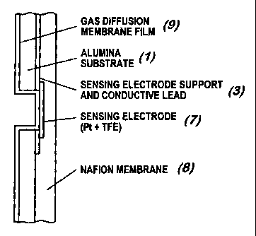
Over the empty alumina surface (the surface with no printed leads and
electrodes) a gas-permeable diffusion film (9) is deposited in one
configuration of
the invention. This film is made to conform to the sensor electrode over the
holes
(as shown in Figure 3), or hangs loose over the (sensor) sensing electrode
(7).
The substrate (with multiple arrays of printed conductors), the Nafion
membrane
(with multiple sensing electrode discs), and the gas-permeable film are
arranged as
shown in the schematic representation of Figure 3. After all the components
are
unitized, the resulting structure is cut in individual sensor units.
An additional advantage of this structure is that it allows for a water
reservoir
over the Nafion membrane on the opposite, or back side from where the sensing
electrode is located as shown in Figure 4c.
A schematic drawing of the sensor cell assembly of this invention is shown
in Figure 4. In a preferred embodiment of this invention a hole of
approximately
80 mils (0.080 in) is formed in a film type substrate and sensing electrode
contacts
(6), and Pt counter (5) and reference electrodes (4) are then deposited on the
substrate (1) surface as shown in Figure 4a. In an alternative embodiment of
this
invention the hole (2) is drilled directly through the non-conductive
substrate and
integral sensing electrode contact structure. As a result the sample gas has
direct
contact through the substrate hole with the sensing electrode as shown in
Figure
CA 02360595 2001-07-18
WO 01/36956 PCT/US00/31660
-7-
4b. This film type substrate structure is mounted in a sensor housing (10) as
shown in Figure 4c with a solid ionomer membrane (Nafion 117). The Pt sensing
electrode (with hole in center) and solid counter and reference electrodes are
compressed tightly against the Nafion membrane. The fixture as shown in
Figure 4 has a water reservoir (11) on the opposite side of the membrane from
where the electrodes are located. The reservoir (11) is filled with distilled
water
and wets the membrane, thus fixing and controlling the water content of the
membrane and electrode assemblies. The reservoir (11) is sealed with a cap.
(20).
The film type sensor configuration from above is integrated with a
potentiostat and a voltage of approximately +0.1 V is applied to the Pt
sensing
electrode with respect to a Pt/Air (Oz) reference. This corresponds to an
applied
potentiostatic voltage of approximately 1.16 V with respect to a normal
hydrogen
electrode (NHE).
Gas samples of air and 7.4 ppm S02 in air are introduced into the sampling
port of the fixture described above. The gas flow is approximately 60 cm3/min
and
temperature is approximately 25°C. The sample gas diffuses through the
80-mil
hole in the non-conductive substrate and electrochemically reactes at the
exposed
sensing electrode/solid ionomer electrolyte surface. Humidification is
provided by
the liquid water in the reservoir which soaks the opposite, or back side of
the
membrane as to where the electrode structures are located.
The background response signal with air is 30 nanoamps (nA). The
response signal with 7.4 ppm S02 in air is 135 nA. This corresponds to a net
response signal for 7.4 ppm SOZ in air of 105 nA or 14.2 nA/ppm per 80-mil
hole. It
is possible to increase the magnitude of signal and signal-to-noise ratio by
increasing the number of holes in the substrate above the integral sensing
electrode structure.
CA 02360595 2001-07-18
WO 01/36956 PCT/US00/31660
_g_
It is also possible, with this configuration, to detect other oxidizable or
reducible gases such as CO, NO, N02, H2S, ozone, COZ, hydrogen, hydrazine,
ammonia, HCI, alcohols and acetone.
Referring to Figures 5 and 6, a block diagram of the sensor control circuit
(13) is shown. The sensor control circuit (13) is designed to: 1 ) control the
potential of the sensing electrode (7) at a predetermined voltage (the
"potentiostatic
voltage", or "EPot'); 2) measure the temperature; 3) convert the gas
concentration-
related current to a temperature-compensated voltage signal; and 4) provide
properly amplified voltage to the data acquisition/storage microprocessor
(14). An
on-board micro power-regulated power supply (16) uses the microprocessor's
(14)
power supply to provide the required t3.9 volts for the sensor circuitry. The
DC
power can be supplied by a 6-V battery (16d) or an AC adaptor (16e).
The control amplifier portion (17b) of the sensor control circuit (13)
consists
of a micro power operational amplifier (e.g., MAX407 or LM6062). The sensing
(7),
counter (5) and reference (4) electrode portions of the sensor assembly (1)
are in
the feedback loop of the control amplifier (17b) as shown in Figure 5, a
standard
configuration for potentiostat circuits. An adjustable voltage divider (17a)
allows
the polarizing voltage (EPot) to be set at a predetermined voltage range such
as 0 to
50 mV. This signal is compared to the reference electrode (7) voltage (which
appears with it at the summing junction) by the control amplifier (17b) of the
sensor
control circuit (13). The latter adjusts the current through the sensor cell
(10) to
minimize the difference between the EPot and the reference electrode (4)
voltages.
The resulting sensor cell assembly (19) current (flow of electrons from
sensing electrode (7) to counting electrode (5)), which is linearly related to
the
concentration of gas, is transformed into a voltage signal by the current-to-
voltage
converter (15a). Temperature compensation of the sensor signal is effected in
the
next stage of amplification (15b) using a thermistor (18a) which is positioned
in the
gas sensor housing (10). The last stage of amplification (15c) provides the
CA 02360595 2003-11-06
63751-295
-9-
necessary inversion of the voltage signal as well as gain adjustment, to
permit
calibration for normal variations in sensitivity among sensors. The same type
of
micro power operational ampffier is used for these stages (15a), (15b), (15c)
as for
the control amplfier (15b). The transformed current signal is directed to an
AID
channel on the data acquisition board of the microprocessor (14).
Power for the sensor control circuit (13) is provided by a Duracell 6-V
battery
(16d) (PX 28A or 28L) through a micro power-regulated power supply (16). The
power supply (16) utilizes a voltage inverter (e.g., ICt_ 7660) (16a) to
convert the
positive battery voltage to a negative voltage of the same magnitude, and a
positive voltage regulator (e.g., MAX663) (16c) and negative voltage regulator
(e.g., MAX 664) (16b) to provide a stable t3.9 volts.
The film type gas or vapor sensing instrument (12), as shown in Figure 6,
includes the sensor cell assembly (19), potential-control circuitry (13), and
the
microprocessor (14) with the data acquisition-recording unit. The sensing
instrument (12) is preferably battery operated, and has the ability to sample
the gas
or vapor and temperature signals at intervals and store in the random access
memory (RAM) on the data acquisition board days to weeks of data. The data
acquisition circuit microprocessor is programmed to sample and store the gas
concentration signals at preset intervals. Data are off loaded to. a personal
computer by accessing the microprocessor through an RS232 port.
The sensor cell assembly (19) and its potential-control circuit (13) are
integrated with a battery-operated microprocessor (14) of 32K memory, which
samples the sensor signal as well as temperature and other signals at 10-, 20-
, or
30-second intervals and stores an average value at intervals of 2, 5, or 10
minutes
according to a programmable protocol. The data acquisitionlstorage unit in the
microprocessor (14) can record 8 days of data, storing at 2-minute intervals,
or up
to 40 days storing at 10-minute intervals. In clinical testing to date, a 2-
minute
interval is suitable for one-day clinical studies and a 10-minute interval is
*Trade-mark
CA 02360595 2001-07-18
WO 01/36956 PCT/US00/31660
-10-
appropriate for extended use. The microprocessor (14) with data
acquisition/logic
circuit can be programmed to sample more than one analog signal from the
control
circuit (13), and to convert these to digital signals and store them (i.e.,
gas
concentration and temperature) at preset intervals together with real-time
data.
Data are off-loaded to a personal computer by accessing the microprocessor
(14)
through an RS232 port. After downloading, the digital data are converted to
engineering units of gas concentration and temperature, and can be graphed by
a
menu-driven Lotus~ 123 spreadsheet. Through a potentiometer in the gain
amplifier circuit (15c), the device can be calibrated with calibrated gas
samples, to
indicate gas concentrations in the ambient. The potential-control circuit (13)
shown
in Figure 5 is powered, in a preferred embodiment, by six 1'/Z volt AA-size
batteries (16d). A typical microprocessor (14) with data acquisition-recording
capability that has been successfully used is sold by ONSET Computers,
Falmouth, MA, under the product name of "Tattletale Lite~." The sensor cell
assembly (19) with its control circuit (13) is also designed to yield a
current or
voltage signal proportional to gas flux that could be used to continuously
transmit
the data to a remote receiving device or central monitoring station or unit.
The sensing electrodes can be organized in multiple arrays or sets
containing a necessary number of counter or reference electrodes. Reference
electrodes such as Pt/air (02), Pt02, or dynamic hydrogen electrode as
described
by Giner (1964) may be employed. Electrically driven 3- or 2-electrode film
type
configurations may be employed using potentiostatic, potentiodynamic or
potential
control. Two-electrode configurations require a reversible or stable counter-
reference electrode such as Pt/air (OZ), Pt02 or Pt/H2 which has a higher BET
(Brunauer, Emmett, Teller) surface area (25 m2/g or larger) and/or larger
geometric
surface areas than the sensing lectrode.
Electrochemically reversible electrodes may be used in 3 or 2 electrode
configurations, but especially in a 2 electrode arrangement where the counter
electrode also acts as a reference electrode. Electrochemically reversible
CA 02360595 2001-07-18
WO 01/36956 PCT/US00/31660
-11-
electrodes are constructed of stable catalyst materials and usually have a
relatively
large electrochemical active surface area so that they remain stable and their
potential is not perturbed by small current flow. Examples include Pt02 and
Ag/AgCI electrodes.