Language selection

Search

Patent 2360607 Summary

Third-party information liability

Some of the information on this Web page has been provided by external sources. The Government of Canada is not responsible for the accuracy, reliability or currency of the information supplied by external sources. Users wishing to rely upon this information should consult directly with the source of the information. Content provided by external sources is not subject to official languages, privacy and accessibility requirements.

Claims and Abstract availability

Any discrepancies in the text and image of the Claims and Abstract are due to differing posting times. Text of the Claims and Abstract are posted:

  • At the time the application is open to public inspection;
  • At the time of issue of the patent (grant).
(12) Patent: (11) CA 2360607
(54) English Title: STORAGE TRAY FOR USE WITH A TONNEAU COVER ASSEMBLY
(54) French Title: PLATEAU DE RANGEMENT CONCU POUR SERVIR AVEC UN COUVRE-TONNEAU
Status: Deemed expired
Bibliographic Data
(51) International Patent Classification (IPC):
  • B60P 7/02 (2006.01)
(72) Inventors :
  • HENDERSON, JACK V. (United States of America)
(73) Owners :
  • DECOMA INTERNATIONAL INC. (Canada)
(71) Applicants :
  • DECOMA INTERNATIONAL INC. (Canada)
(74) Agent: BRANDT, KERSTIN B.
(74) Associate agent:
(45) Issued: 2010-05-18
(22) Filed Date: 2001-10-29
(41) Open to Public Inspection: 2002-05-02
Examination requested: 2006-10-17
Availability of licence: N/A
(25) Language of filing: English

Patent Cooperation Treaty (PCT): No

(30) Application Priority Data:
Application No. Country/Territory Date
60/245,447 United States of America 2000-11-02

Abstracts

English Abstract

A tonneau cover assembly is adapted to be secured to a vehicle having a cargo bed and side walls. The tonneau cover assembly includes a panel that extends between two sides, a front edge and a back edge. The panel is movable between open and closed positions. A hinge mechanism includes first and second attachment brackets wherein the second attachment bracket is secured to the panel. A link mechanism extends between two ends wherein the first end is secured to the panel. A storage tray is secured to the first attachment bracket and the second link end. The storage tray is supported by the panel and moves relative to the panel when the panel moves.


French Abstract

Ensemble couvercle conçu pour être fixé à un véhicule doté d'une plate-forme de chargement et de parois latérales. L'ensemble couvercle comprend un panneau qui s'étend entre deux côtés, un bord avant et un bord arrière. Le panneau peut passer d'une position ouverte à une position fermée. Une charnière comprend une première et une seconde pièces de fixation, dont l'une est fixée au panneau. Un mécanisme de liaison comprend deux extrémités, dont l'une est fixée au panneau. Un plateau de transport est fixé à la première pièce de fixation et à la seconde extrémité du mécanisme de liaison. Le plateau de transport est supporté par le panneau et se déplace par rapport au panneau lorsque celui-ci bouge.

Claims

Note: Claims are shown in the official language in which they were submitted.


Claims

What is claimed is:


1. A tonneau cover assembly adapted to be secured to a vehicle having a cargo
bed
and a sidewall disposed adjacent thereto, said tonneau cover assembly
comprising:
a panel extending between first and second side edges and front and rear
edges, said panel movable between an open position and a closed position;
a hinge mechanism including first and second attachment brackets, said
second attachment bracket fixedly secured to said panel;
a link mechanism extending between first and second link ends, said first link

end fixedly secured to said panel; and
a storage tray secured to said second link end and said first attachment
bracket
such that said storage tray is supported by said panel and moves relative
thereto when
said panel moves.


2. A tonneau cover assembly as set forth in claim 1 wherein said storage tray
includes
a positioning ledge for abutting the sidewall when said panel is moving to and
from
said open position such that said storage tray remains horizontal as said
panel moves
to and from said open position.


3. A tonneau cover assembly as set forth in claim 2 including a locking
mechanism
for securing said storage tray to said panel to maintain said storage tray in
a position
abutting said panel preventing access to said storage tray.


4. A tonneau cover assembly as set forth in claim 3 wherein said link
mechanism is
longer than said hinge mechanism allowing a portion of said storage tray
disposed
adjacent said link mechanism to move from said panel a distance greater than a

second portion of said storage tray disposed adjacent said hinge mechanism.


5. A tonneau cover assembly as set forth in claim 4 wherein said link
mechanism
includes first and second links.


6


6. A tonneau cover assembly as set forth in claim 5 wherein said first link is
rotatably
secured to said storage tray.


7. A tonneau cover assembly as set forth in claim 6 wherein said second link
is
rotatably secured to said panel.


8. A tonneau cover assembly as set forth in claim 7 wherein said first and
second link
are rotatably connected to each other.


9. A tonneau cover assembly as set forth in claim 8 wherein said locking
mechanism
includes a pin.


10. A tonneau cover assembly as set forth in claim 9 wherein said locking
mechanism
further includes a hole extending through said storage tray for receiving said
pin
therethrough.


11. A tonneau cover assembly as set forth in claim 10 wherein said locking
mechanism further includes a second hole extending through said panel for
receiving
said pin therethrough when said storage tray is abutting said panel whereby
said pin
prevents said storage tray from moving away from said panel as said panel
moves
toward said open position.


12. A tonneau cover assembly adapted to be secured to a vehicle having a cargo
bed
and a sidewall disposed adjacent thereto, said tonneau cover assembly
comprising:
a panel extending between first and second side edges and front and rear
edges, said panel movable between an open position and a closed position;
a hinge mechanism including first and second attachment brackets, said
second attachment bracket fixedly secured to said panel;
a link mechanism extending between first and second link ends, said first link

end fixedly secured to said panel;
a storage tray secured to said second link end and said first attachment
bracket
such that said storage tray is supported by said panel and moves relative
thereto when
said panel moves; and


7


a locking mechanism for securing said storage tray to said panel to maintain
said storage tray in a position abutting said panel preventing access to said
storage
tray.


13. A tonneau cover assembly as set forth in claim 12 wherein said storage
tray
includes a positioning ledge for abutting the sidewall when said panel is
moving to
and from said open position such that said storage tray remains horizontal as
said
panel moves to and from said open position.


14. A tonneau cover assembly as set forth in claim 12 wherein said link
mechanism is
longer than said hinge mechanism allowing a portion of said storage tray
disposed
adjacent said link mechanism to move from said panel a distance greater than a

second portion of said storage tray disposed adjacent said hinge mechanism.


15. A tonneau cover assembly as set forth in claim 13 wherein said link
mechanism
includes first and second links.


16. A tonneau cover assembly as set forth in claim 15 wherein said first link
is
rotatable secured to said storage tray.


17. A tonneau cover assembly as set forth in claim 16 wherein said second link
is
rotatably secured to said panel.


18. A tonneau cover assembly as set forth in claim 17 wherein said first and
second
link are rotatably connected to each other.


19. A tonneau cover assembly as set forth in claim 18 wherein said locking
mechanism includes a pin.


20. A tonneau cover assembly as set forth in claim 19 wherein said locking
mechanism further includes a hole extending through said storage tray for
receiving
said pin therethrough.


8


21. A tonneau cover assembly as set forth in claim 20 wherein said locking
mechanism further includes a second hole extending through said panel for
receiving
said pin therethrough when said storage tray is abutting said panel whereby
said pin
prevents said storage tray from moving away from said panel as said panel
moves
toward said open position.


9

Description

Note: Descriptions are shown in the official language in which they were submitted.


CA 02360607 2001-10-29

STORAGE TRAY FOR USE WITH A TONNEAU COVER ASSEMBLY
BACKGROUND ART

Field of the Invention

This invention relates to a storage tray. In particular, this invention
relates to a
storage tray fixedly attached to the underside of a rigid tonneau cover so as
to expose the
contents therein when the tonneau cover is pivoted to an open position.

Description of the Related Art

Tonneau covers are becoming increasingly popular as an added option for pickup
trucks. The tonneau cover overlies the cargo bed of the pickup truck to
provide covered
storage in the bed and also improve vehicle aerodynamics.

Pickup trucks are commonly used for storing and transporting items. With the
addition of a tonneau cover, ease of access to cargo, especially small cargo,
carried in the
truck bed is more difficult. A storage compartment within easy access when the
tonneau
cover is opened enables small cargo to be placed within easy reach and is
therefore
desirable.

SUMMARY OF THE INVENTION

A tonneau cover assembly is adapted to be secured to a vehicle having a cargo
bed and side walls. The tonneau cover assembly includes a panel that extends
between
two sides, a front edge and a back edge. The panel is movable between open and
closed
1


CA 02360607 2001-10-29

positions. A hinge mechanism includes first and second attachment brackets
wherein the
second attachment bracket is secured to the panel. A link mechanism extends
between
two ends wherein the first end is secured to the panel. A storage tray is
secured to the
first attachment bracket and the second link end. The storage tray is
supported by the
panel and moves relative to the panel when the panel moves.

BRIEF DESCRIPTION OF THE DRAWINGS

Advantages of the invention will be readily appreciated as the same becomes
better understood by reference to the following detailed description when
considered in
connection with the accompanying drawings, wherein:

Figure 1 is a side view of the tonneau cover and storage tray of the present
invention in the closed position;

Figure 2 is a side view of the tonneau cover and the storage tray of the
present
invention in an open position;

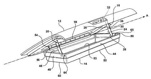
Figure 3 is a perspective view of the tonneau cover and the storage tray in an
open
position; and

Figure 4 is a perspective view of the storage tray and tonneau cover
illustrating
the locked out position.

DETAILED DESCRIPTION OF THE PREFERRED EMBODIMENT
Referring to Figure 1, a tonneau cover assembly is generally indicated at 10.
The
tonneau cover assembly 10 includes a panel 12, storage tray 14, a hinge
assembly 16, and
link assemblies 18, 20. The tonneau cover assembly 10 is a rigid, generally
planar panel

2


CA 02360607 2001-10-29

12 constructed of plastic, fiberglass, or the like, that is used for covering
a cargo bed 21
of a pickup truck 22 and is pivotally attached thereto. In an alternative
embodiment, the
tonneau cover 10 may be fabric extending over a hard skeletal structure
(neither shown).

As shown in Figure 3, the storage tray 14 includes a generally rectangular
shape,
which is formed from any suitable material such as a thermoset or
thermoplastic. The
storage tray 14 is mounted to an underside of the panel 12. The tray 14
includes a bottom
portion 52 having a position ledge 53. The bottom portion 52 is a generally
horizontal
plane defined by a perimeter edge 60. Generally parallel front and rear
vertical walls 44,
46 are interconnected by generally parallel vertical side members 48, 50, each
extending

upwardly from the perimeter edge 60 of the bottom portion 52 and defining an
interior
area. Furthermore, the storage tray 14 may have additional interior walls
which form
smaller compartmentalized areas.

As shown in Figures 2 and 3, the hinge assembly 16 is fixedly attached between
the storage tray 14 and panel 12. The hinge 16 can be any type of hinge
mechanism, i.e.,
dual hinge, piano hinge, or similar, as known to one of ordinary skill in the
art. The

hinge 16 has a first attachment bracket 56 which is fixedly attached to the
rear wall 46.
The hinge 54 further has a second attachment bracket 58 which is fixedly
attached to the
panel 12. The first and second attachment brackets 56, 58 are pivotally
connected
together to create pivot axis A for providing rotation between the tonneau
cover 12 and
the tray 14.

The side members 48, 50 are rotationally connected to the links assemblies 18,
20.
The link assemblies 18, 20 are mirror images and, therefore, only link
assembly 18 will
be described. Referring to Figure 2, the link assembly 18 includes a first and
second link
3


CA 02360607 2001-10-29

24, 26. The first link 24 has a first end 28 rotationally connected to the
storage tray 14
and a second distal end 30. The second link 26 has a first end 32 which is
rotationally
connected to the panel 12 and a second distal end 34 which is rotationally
connected to
the second distal end 30 of the first link 24. The link assemblies 18, 20 can
be link type,

wire type or a similar mechanism which will prevent further rotational
movement of the
storage tray 10 when a predetermined position has been reached.

Referring to Figure 3, each side wall 48, 50 of the storage tray 14 further
includes
a tray lockout feature 64, 65. Each tray lockout feature 64, 65 is similar in
function and
design, therefore, lockout feature 64 will be described. Referring now to
Figure 4, the

tray lockout feature 64 includes a tray lockout opening or hole 66 and a
tonneau lockout
opening or hole 68. The tray lockout opening 66 is mounted such that it
corresponds to a
similar opposing tonneau lockout opening 68 in the panel 12 when in the closed
position.
Each lockout opening 66, 68 accepts a lockout pin 70. The lockout pin 70 is
generally T-
shaped and is used to hold the storage tray assembly 10 in the closed position
while the

panel 12 is opened to allow for access into the cargo bed 21 of the pickup
truck 22.
Alternatively, the lockout opening 66 can be located in the front wall 44 of
the storage
tray 14. It should be recognized that this is one such lock out device and
others could be
used in the alternative.

Referring to Figure 1, in operation, when the panel 12 is lifted, the front
wall 44
of the storage tray 14 rests against the pickup truck 22 keeping the storage
tray 14
generally parallel with the ground while allowing the panel 12 to open.
Referring to
Figure 3, the storage tray 14 is allowed to rotate about pivot axis A until
the link
assemblies 18, 20 become taut, thus preventing further rotation. When the link
4


CA 02360607 2001-10-29

assemblies 18, 20 are taut and the panel 12 is in the open position, the
storage tray 14 is
presented at a level which allows for easy access to the interior of the
storage tray 14, as
shown in Figure 2.

Referring again to Figure 1, when the panel 12 is closed, the bottom portion
52 of
the tray 14 opposite the front wall 44 contacts the pickup truck 22, thereby
preventing the
front wall 44 from moving but allowing for rotation of the storage tray
assembly 10 about
pivot axis A relative to the panel 12. The pickup truck bed 22 holds the
storage tray
assembly 10 against the panel 12 when in the closed position creating a lid
which
prevents spillage of the contents within the storage tray 14.

Referring to Figure 4, the storage tray 14 of the tonneau cover assembly 10
may
be locked out by aligning the tray opening 66 with the tonneau opening 68 and
inserting
the lockout pin 70 through both openings 66, 68. The storage tray 14 is then
held in place
relative to the tonneau cover 12 when being opened which allows for access to
the cargo
bed 21 of the pickup truck 22.

The invention has been described in an illustrative manner. It is to be
understood
that the terminology, which has been used, is intended to be in the nature of
words of
description rather than of limitation.

Many modifications and variations of the invention are possible in light of
the
above teachings. Therefore, within the scope of the appended claims, the
invention may
be practiced other than as specifically described.

5

Representative Drawing
A single figure which represents the drawing illustrating the invention.
Administrative Status

For a clearer understanding of the status of the application/patent presented on this page, the site Disclaimer , as well as the definitions for Patent , Administrative Status , Maintenance Fee  and Payment History  should be consulted.

Administrative Status

Title Date
Forecasted Issue Date 2010-05-18
(22) Filed 2001-10-29
(41) Open to Public Inspection 2002-05-02
Examination Requested 2006-10-17
(45) Issued 2010-05-18
Deemed Expired 2011-10-31

Abandonment History

There is no abandonment history.

Payment History

Fee Type Anniversary Year Due Date Amount Paid Paid Date
Registration of a document - section 124 $100.00 2001-10-29
Application Fee $300.00 2001-10-29
Maintenance Fee - Application - New Act 2 2003-10-29 $100.00 2003-09-22
Maintenance Fee - Application - New Act 3 2004-10-29 $100.00 2004-09-15
Maintenance Fee - Application - New Act 4 2005-10-31 $100.00 2005-09-26
Maintenance Fee - Application - New Act 5 2006-10-30 $200.00 2006-09-14
Request for Examination $800.00 2006-10-17
Maintenance Fee - Application - New Act 6 2007-10-29 $200.00 2007-09-20
Maintenance Fee - Application - New Act 7 2008-10-29 $200.00 2008-09-17
Maintenance Fee - Application - New Act 8 2009-10-29 $200.00 2009-08-31
Final Fee $300.00 2010-03-04
Owners on Record

Note: Records showing the ownership history in alphabetical order.

Current Owners on Record
DECOMA INTERNATIONAL INC.
Past Owners on Record
HENDERSON, JACK V.
Past Owners that do not appear in the "Owners on Record" listing will appear in other documentation within the application.
Documents

To view selected files, please enter reCAPTCHA code :


To view images, click a link in the Document Description column. To download the documents, select one or more checkboxes in the first column and then click the "Download Selected in PDF format (Zip Archive)" or the "Download Selected as Single PDF" button.

List of published and non-published patent-specific documents on the CPD .

If you have any difficulty accessing content, you can call the Client Service Centre at 1-866-997-1936 or send them an e-mail at CIPO Client Service Centre.


Document
Description 
Date
(yyyy-mm-dd) 
Number of pages   Size of Image (KB) 
Cover Page 2002-04-26 1 47
Representative Drawing 2002-02-05 1 19
Abstract 2001-10-29 1 18
Description 2001-10-29 5 191
Claims 2001-10-29 5 132
Drawings 2001-10-29 4 156
Claims 2009-08-14 4 135
Drawings 2009-08-14 3 50
Representative Drawing 2009-09-25 1 15
Cover Page 2010-04-21 1 45
Assignment 2001-10-29 3 126
Prosecution-Amendment 2006-10-17 1 29
Correspondence 2006-10-17 2 46
Correspondence 2006-11-02 1 15
Correspondence 2006-11-02 1 16
Prosecution-Amendment 2006-11-30 1 26
Correspondence 2010-03-04 1 27
Prosecution-Amendment 2009-02-16 2 48
Prosecution-Amendment 2009-08-14 10 264
Correspondence 2009-09-29 1 31