Note: Descriptions are shown in the official language in which they were submitted.
CA 02360682 2005-06-28
MOUNTING OF A ROTATABLE CHISEL IN MINING MACHINERY
The invention relates to rotatable chisel especially for mining machines,
which is used mostly in conveying and cutting heads of cutter roller loaders.
The
rotating chisel comprises a shaft and a working part with a flange for support
at the
front of a chisel holder. And the end of the shaft part of the rotating
chisel, an elastic
friction ring is disposed. The friction ring is slipped onto a section,
constructed for
this purpose, of the chisel shaft, which is provided with an end flange. The
end flange
and the part of the shaft, constructed for accommodating the friction ring,
protrude
together with the friction ring partly over the edge of the chisel holder, in
which the
chisel is fastened.
Many solutions for constructing chisel shafts are known from the state
of the art and depend upon the safety mechanism employed. The Polish patent
application 316,848 discloses a chisel holder, which is widespread and has a
wide flat
groove in the vicinity of its end. When a chisel is inserted in the holder, an
expansion
sleeve, with surface elements constructed convexly at its surface, engages
this groove
and thus prevents the expulsion of the inserted chisel. In the case of this
solution, the
shaft of the chisel is completely in the chisel holder. It is a disadvantage
of
dissolution that the expansion sleeve, the so-called "clip ring", is relaxed
after
insertion in the chisel holder. A gap therefore remains between its inside and
the
surface of the groove and the small particles of the rock, which have been
removed,
collect in this gap. As a result, the free rotatability of the chisel holder,
which is
important for uniform wear, is made difficult after a certain time. Because of
the
intercalated small particles, it is also difficult, if not impossible, to
compress the
expansion sleeve and, with that, to exchange and a worn out chisel. A similar
construction of the chisel shaft is shown in the British patent 2146058 and
the U.S.
patent 4,484,783.
1
CA 02360682 2001-07-24
Further solutions for structural shapes of shafts and components of the
safety mechanism are unknown from the U.S. patent 4,684,176. In an example
(there
Figure 1), the shaft is short and inserted completely into a hole of the
chisel holder. A
friction expansion sleeve, made from a thin metal sheet, is used over the
whole
surface of the shaft from the end flange to the supporting flange. Such
sleeves are
also known from the Polish patent 173,146 or, for example, from the German
patent
3,233,123. These solutions have the disadvantage that the insertion of the
chisel in
the chisel holder is made difficult, since the sleeve, in the relaxed state,
has a diameter
larger than that of the internal hole of the chisel holder. As the chisel is
driven in, the
sleeve therkore shifts to the upper, cylindrical part of the shaft u~~o the
flange and
prevents further insertion of the chisel into the hole or, in the rever case,
a knocking
out of the whole. The leads to difficulties in underground working conditions.
There are similar problems with the chisel, which is disclosed in the EP
0 295 232 A1 and the sleeve of which also is in contact with the shaft over
almost its
whole length and, at the bottom, is buckled and engages a groove, and, at the
top, is
angled to the outside. As a result, when the chisel is inserted into the seat
of the chisel
holder, the sleeve once again is expanded and is pushed upward, which can lead
to
jamming.
, In a different embodiment of the already mentioned U.S. patent
4,684,176 (Figure 3), there is a construction, for which the shaft of the
chisel is longer
than the hole of the chisel holder and protrudes from the latter. Normally, a
narrow
groove, into which a blockage in the form of a safety ring, a clamp or a
splint is
inserted, is assigned here to the end section of the shaft. Such solutions
lead to
difficulties, in as much as contamination collects between the shaft and the
chisel
holder hole and, due to friction wear, results in an ever increasing clearance
at the
inner hole. When the chisel holder hole has been expanded very much, the
safety
AMENDED
2 SHEET
CA 02360682 2001-07-24
mechanism may also become ineffective, so that the chisel falls out of the
chisel
holder.
In a different U.S. patent 4,944,559, the groove is disposed at the shaft
of the chisel, which protrudes from the hole of the chisel holder. In the case
of this
arrangement, there are sometimes even double safety mechanisms, predominantly
in
the form of two Seger rings or of one Seger ring and a locking barrier.
Starting out from this state of the art, it is an object of the invention to
indicate a generic chisel and a safety mechanism preventing the chisel falling
out
during operation, which avoid the disadvantages of the previously known
solutions,
can be handled easily, have a simple structure and facilitate exchanging the
chisel.
The solution shall be usable equally for chisels, the shaft of which has a
uniform
diameter throughout its length, as well as for chisels, the shaft of which has
a stepped
diameter. The invention shall be suitable for fastening the chisel directly in
the chisel
holder as well as for fastening it in an intermediate sleeve.
Pursuant to the invention, this objective is accomplished owing to the
fact that the end part of the chisel shaft is equipped with a projection,
which is
constructed as a lug and sloped to both sides, and that is, provided with
chamfers. A
friction ring, the diameter of which in the relaxed state is larger than the
diameter of
the hole of the chisel holder, is placed on the lug. At its upper and lower
ends, the
friction ring has inwardly inclined slopes, which are adapted to the chamfers
of the
lug. The chamfers of the lug and the slopes of the friction ring, inclined
inwards on
both side, cause of the friction ring to remain in the region of the lug
during the
insertion as well as during the expulsion of the chisel and prevent it from
being
pushed onto another part of the shaft. Because of this restricted guidance,
there is no
undesirable expansion of the friction ring. Moreover, in comparison with
conventional shaft shapes with broad, smoothed accommodating grooves for a
sleeve
or a friction ring, the lug-shaped accommodating region of the shaft has the
advantage
3 AMENDED
SHEET
CA 02360682 2005-06-28
for the friction ring that the lug does not represent an appreciable thinning
of the
material relative to the rest of the shaft and, in this respect, contributes,
in addition to
the rest of the shaft region, to the stabilization of the chisel during the
rotation of the
latter.
For the inventive solution, the effective fastening, as well as the easy,
rapid and reliable handling during the fastening are of advantage. It also
advantageous
that a separate blocking piece does not have to be provided, since the
friction ring is
placed on the shaft of the chisel already by the manufacturer and is disposed
of
together with the worn out chisel. This construction of the safety mechanism
for the
chisel is not expensive and perhaps even less expensive than that of known
safety
mechanisms. Moreover, the inventive construction ensures and unimpeded
rotation of
the chisel in the chisel holder and, with that, a uniform wear. Since the lug
is
constructed as a simple extension of the shaft, the stability of the shaft,
introduced
into the chisel holder, is increased. The expansion of the chisel holder hole
and the
eventual breakage of the chisel, which are customary when chisels with short
shafts
are used, are avoided.
According to an aspect of the present invention there is provided a rotating
chisel assembly for insertion in a chisel holder, comprising a shaft and a
working part
with a flange, which acts as a support at a front of the chisel holder, when
the shaft of the
rotating chisel is inserted in an accommodating hole of the chisel holder, the
shaft having
a lug provided with an end flange and an upper chamfer connecting to an upper
shaft part
of the shaft, and a lower chamfer connecting the end flange, and a friction
ring disposed
over the lug and having upper and lower slopes adapted to the upper and lower
chamfers
of the lug.
4
CA 02360682 2005-06-28
According to another aspect of the present invention there is provided a
chisel arrangement for mining machines, comprising a rotatable chisel
including a
working part, a supporting flange arranged adjacent the working part, and a
shaft
arranged adjacent the supporting flange, the shaft having a lug and an end
flange at an
end opposite from the supporting flange, a chisel holder arranged around a
portion of the
shaft, and a friction ring arranged around the lug and at least partially
against the chisel
holder, the end flange of the shaft, a portion of the lug and a portion of the
friction ring
being arranged exterior of the chisel holder.
Further advantages of the invention arise out of the following description
of a preferred embodiment. In the drawings,
Figure 1 shows a partial view of the rotating chisel with a uniform shaft and
slipped-on friction ring, inserted in a chisel holder, which is shown in
section,
Figure 2 shows a view of the rotating chisel shaft with slipped-on friction
ring
during the insertion into the chisel holder, partly in section
4a
CA 02360682 2001-07-24
Figure 3 shows the shaft of the rotating chisel of Figures 1 and 2, partly in
section,
Figure 4 shows a side view of the friction ring of Figure 1 and 2 from the
direction of the slot in the ring, partly in section,
Figure 5 shows a plan view of the friction ring and
Figure 6 shows an enlargement of the chamfer of the end edge of the friction
ring of Figure 4.
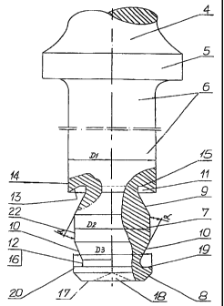
Pursuant to the invention, the rotating chisel has a working part 4 and a
mandrel-shaped shaft 6, which is connected with the working part 4 by a
supporting
flange 5. After the insertion of the rotating chisel in the chisel holder 1,
the
supporting flange 5 lies against the front 3 of the chisel holder 1. In its
end section,
the shaft 6 has a region, which is constructed as a lug 7 and is sloped to
both sides and
has a chamfer 9 to the side of the upper shaft part 6 and a chamfer 10 to the
side of the
end flange 8. Advisably, both chamfers 9, 10 are constructed identically and
enclose
between themselves and the peripheral surface 22 of the lug 7 an angle a of 10
to
35 and preferably of 25 . The diameter D2 of the lug 7 is smaller than the
diameter
D 1 of the shaft 6 and the diameter D3 of the side surface 20 of the end
flange 8. It is
advantageous if the diameter D3 of the end flange 8 is somewhat smaller than
the
diameter D 1 of the shaft 6. Between the chamfer 9 and the inner inclined
surface 13
of the shaft 6, a recess 11 is formed with a bottom 15 and with a straight or
curved
contour and, between the chamfer 10 and the inner side 19 of the end flange 8,
a
groove 12 with a bottom 16 with a straight contour is formed. A friction ring
23,
which has slopes 25 to both sides and forms a slot 26 between two edges 28, is
placed
on the lug 7. Between themselves and the surface 20 for off the friction ring
23, the
slopes 25 enclose an angle 0, which is between 10 and 35 and preferably is 25
, so
that the slopes 25 are aligned as far as possible according to the chamfers 9
and 10 of
AMENDED
SHEET
CA 02360682 2001-07-24
the lug 7. The diameter dl of the friction ring 23, in the relaxed state, is
larger than
the diameter of the hole 2 of the chisel holder 1. However, the diameters d2
of the
end edges 13 of the slopes 25 of the friction ring 23 are smaller than the
diameter D 1
of the shaft 6 and the diameter D3 of the side surface 20 of the end flange 8.
As a result, the end edges 30 of the slopes 25 of the friction ring 23 are
disposed, on the one hand, in the recess and, on the other, in the groove 12.
Consequently, the end edges 30 cannot be pushed out of the recess 11 and the
groove
12 even in the relaxed state, not even when the friction ring 23 opposite the
lug 7 is in
its outermost end position. The diameters of the lug 7 and of the friction
ring 23 and
the diamett of the hole 2 of the chisel holder 1 are matched to one another in
such a
manner, that the friction ring 23, the wall of which has a thickness~; with
its surface
20 exerts on the surface of the hole 2 a pressure, which is so large, that the
frictional
force prevents a displacement of the chisel 4 in the axial direction and the
chisel 4 is
reliably prevented from falling out of the chisel holder 1. Accordingly, the
slot 26 is
constructed so that its edges 28 cannot contact one another even when the
friction ring
23 is stressed. At the same time, in order to assure free rotatability of the
chisel 4 in
the chisel holder 1, there is a gap 21 between the inside 27 of the friction
ring 23 and
the peripheral surface 22 of the lug 7. It is also important that only the
surface 24 for
of the friction ring 23 is in contact with the hole 2. For this reason, it is
advantageous
if the slopes 25 of the friction ring 23, from their transition 29 to the
surface 24 up to
the exid edge 30 are shorter than the chamfers 9, 10 of the lug 7, so that the
end edges
30 are not in contact, on the one hand, with the inner inclined surface 13 of
the shaft 6
and, on the other, with the inside 19 of the end flange 8. The inner inclined
surface 13
advisably extends at an angle of less than 90 (Figure 3) towards the
peripheral
surface 14 of the upper shaft part 6, so that, when the chisel 4 is inserted
in the chisel
holder 1, the upper end edge 30 points in the direction of the bottom 15 of
the recess
11. In addition, the end edges 30 are chamfered at an angle x of about 15 to
the outer
side, in order to prevent the end edges 30 being pushed out of the recess 11
and the
groove 12 even when there are larger manufacturing errors. In order to
facilitate the
6 AMENDED
SHEET
CA 02360682 2001-07-24
insertion of the chisel 4 in the chisel holder 1, the transitions 29 between
the surface
24 and the slopes 25 advisably have a radius r (Figure 4), as a result of
which the
insertion of the chisel 4 can be accomplished even without a hammer by the
exertion
of a small force. This applies even in the case of friction rings 23, which
have been
hardened extensively by a heat treatment. In order to make it easier to slip
the friction
ring 23 onto the lug 7 and to take it off once again, the center parts of the
edges 28
have recesses 31, which prevent pliers slipping off during a manipulation. In
order to
make it easier to drive out the chisel 4 especially in the case of heavy
underground
work, a small recess 18 is provided at the front side 17 of the end flange 8.
This
recess 18 prevents a tool slipping off from the front side 17, when blows are
applied
to it in order to drive the chisel 4 out of the chisel holder 1.
7 IAMENDEb]
SHEET
CA 02360682 2001-07-24
List of the Reference Ntmexals
1. chisel holder
2. hole
3. front
4. working part
5. supporting flange
6. shaft
7. lug
8. end flange
9. chamfer
10. chamfer
11. recec
12. groove
13. inner inclined surface
14. peripheral surface
15. bottom
16. bottom
17. front side
18. recess
19. inner side
20. side surface (of the end flange)
21. gap
22. peripheral surface
23. friction ring
24. surface
25. slope
26. slot
27. inner side
28. edges
29. transition
30. end edge
8 AMENDED
SHEET
CA 02360682 2001-07-24
31. recess
dl diameter
d2 diameter
D 1 diameter
D2 diameter
D3 diameter
g thickness
r radius
a angle
p angle
x angle
9 AMENDED
SHEET