Note: Descriptions are shown in the official language in which they were submitted.
CA 02360845 2001-10-31
Docket No. 740792-132
IMPROVED PROSTHESIS AND METHOD THEREFOR
BACKGROUND OF THE INVENTION
s FIELD OF THE INVENTION
This invention is directed to artificial prosthetic components and
assembly methods therefor for use in a human lower limb prosthesis.
More particularly, this invention is directed to improved human
prostheses and methods therefor wherein the prosthesis comprises
io modular prefabricated components.
DESCRIPTION OF RELATED ART
The most common artificial leg for below knee amputees is of a
is rigid nature. A solid shank connects the socket, which mounts the
artificial leg to the residual limb of the amputee, and the artificial foot.
The shank is often made out of a rigid alloy, such as one containing
titanium, or from shaped wood or plastic. It can be solid for strength, or
it can be hollow for lightness.
2o In a typical conventional prosthesis fabrication technique, a
significant amount of time and effort is wasted in duplicating fabrication
steps. Generally, conventional fabrication includes taking a cast of the
patient's stump and making a socket incorporating the necessary fittings,
including (a) an alignment fitting for angular adjustments; (b) a tubular
2s fitting for length and rotational adjustment; (c) a fitting for linear
adjustments; and (d) an ankle fitting for angular adjustments and to allow
attachment of a foot. The prosthesis is assembled for bench alignment
and the patient is scheduled for dynamic alignment. When the patient
CA 02360845 2001-10-31
and prosthesis are satisfied with both the fit of the socket and the
alignment of the prosthesis, the prosthesis is duplicated in an alignment
device that captures the prosthetic alignment and allows removal of the
metal components and replacing them with polyurethane. The area
s between the top of the keel and the bottom of the socket is foamed in
place, and when the foam hardens, the shank is hand shaped to the
desired configuration between the keel and the socket. The prosthesis is
prepared for the final draping of copolymer plastic. If the finished
prosthesis is not satisfactory and can not be adjusted, the process is
io repeated using the same components. The approximate fabrication time
for this procedure is S to 8 hours.
As an example, U.S. Patent 4,314,398 discloses a method of
making a lower leg prosthesis comprising the steps of (a) forming a
temporary prosthesis socket having an inner shape corresponding to the
is remaining lower leg stump of the amputee to which the prosthesis is to be
attached; (b) forming a test prosthesis by fixing an adjustable position
testing device to the temporary socket and connecting the testing device
to the prosthesis foot through a temporary connecting member; (c) testing
the test prosthesis on the patient and adjusting the testing device so as to
ao obtain a proper alignment of the temporary socket in relation to the
prosthesis foot; (d) providing a positive prosthesis socket in the
temporary socket of the test prosthesis and reproducibly fixing the
assembly comprised of the positive socket, the temporary socket, the
testing device and at least the temporary connecting member in a support
Zs device; (e) removing the test prosthesis parts from the support device; (f)
placing the connecting member adjacent the positive socket in the support
device in the aligned relative position reproducibly set in the support
device in step (d); and (g) forming the prosthesis socket on the positive
2
CA 02360845 2001-10-31
socket while simultaneously securing the connecting member to the
prosthesis socket in the aligned relationship thereby obtaining an
individually aligned lower leg prosthesis. However, the method
associated with this reference requires duplicating assembly steps; i.e.,
s fixing the adjustable position testing device to a temporary socket and
temporarily connecting this device to the prosthesis foot, followed by
removing the test prosthesis and replacing it with a permanent member in
the position formerly occupied by the testing device.
U.S. Patent No. 5,152,800 discloses a below the knee prosthesis
io and method for making the same. The prosthesis includes a socket for
receiving the stump of the below-the-knee amputee, a keel having a
peripheral groove formed about the periphery of a bottom portion of the
keel, a tubular shin member extending from the socket and surrounding
lateral and medial portions of the keel and filling the peripheral grooves
is formed about the bottom portion of the keel leaving a substantial portion
of the bottom of the keel exposed. A resilient foot member is then secured
to the exposed portion of the keel with the material of the tubular shin
member being formed into the grooves of the keel and maintaining such
keel within the shin member. The method thereof includes the steps of
zo forming a socket for receiving a stump of the below-the-knee amputee;
constructing a shin support about the socket including an ankle block and
keel about the socket in accordance with the size and stature of the
amputee; forming a retaining means in a bottom surface of the keel for
retaining the keel in a predetermined position with respect to the socket;
Zs molding a sheet of copolymer material about the shin support, into the
retaining means and over the bottom surface of the keel to form a shin
member; removing the copolymer material from the bottom surface of the
keel; removing a substantial portion of material used to construct the shin
3
CA 02360845 2001-10-31
support from within the shin member; and securing a foot member to the
keel. The method for assembly of this device does not take advantage of
a prefabricated socket adapter/pylon/keel assembly, instead requiring
several distinct steps for assembling the prosthesis including assembling a
s shin support between the socket adapter and the keel, foaming the
support, draping a copolymer exterior on the assembly, and drilling out
the foam shin support.
The prior art also includes continuous one-piece prostheses, such as
that shown in U.S. Pat. No. 5,219,364. That prosthesis offers the
io advantages of light weight and improved energy storage and release
characteristics. Because of its design, however, this prosthesis can
require multiple patient trips to the prosthetist for fitting. In certain
cases
the patient may have to be fitted with another prosthesis which will be
adjusted for various parameters, including height, pylon length, inversion,
is and eversion. Once the prosthesis is adjusted, the measurements from the
adjusted prosthesis are then used to form the one-piece prosthesis,
following a time consuming process. Further, once the prosthesis is
manufactured, adjustments may require repeating and reforming the
prosthesis.
Zo U.S. Patent No. 5,993,487 discloses a prosthetic component for use
in a human lower limb prosthesis. The component consists of an
preformed integrated pylon-keel or foot component. In practice, the
prosthetist would perform a stump measurement on the amputee to
determine the overall height of the prosthesis from which the pylon
as length could be determined, then cut a preformed integrated pylon keel
prosthesis to fit the pylon to an adjustable tube clamp, whereby the clamp
itself is secured to the socket. Then the prosthetist adjusts the tube clamp
for inversion eversion, foot position, and rotation, then the integrated
4
CA 02360845 2001-10-31
pylon/keel is attached to the tube clamp and the apparatus is covered with
plastic. However, this is not a complete prosthesis, but merely the
pylon/keel assembly. Further, the invention requires the use of an
adjustable tube clamp attached to the socket. This additional component
s adds complexity and weight to the structure. Moreover, because the keel
and pylon are an integrated unit, an inventory that could allow for the
naturally occurring variety of needed keel sizes and pylon lengths would
require an extremely large assortment of integrated keel/pylon units.
It would be advantageous to provide an improved method and
io prosthesis therefor that avoids the problems associated with the prior art.
It would further be advantageous to provide a lightweight modular
prosthesis and a method of assembly therefor that can be assembled in a
single sequence of steps, maximizing simplicity and minimizing the time
expended by the wearer in achieving an acceptable fit.
is
The difficulties associated with the prior art are overcome by
providing an improved prosthetic component and method for assembly
Zo wherein the prosthesis comprises prefabricated modular components
including a socket adapter, shank or pylon, a keel, and a foot. The method
for preparation of the improved prosthesis reduces the time required for
prosthesis preparation over that of the prior art, and includes the steps of
making a cast of the remaining leg stump and forming a socket therefor;
Zs placing the socket in an alignment jig; selecting and assembling a
prefabricated keel, pylon, and socket adapter; shaping the socket adapter
to a desired configuration; attaching the socket adapter to the socket;
draping a final coating of copolymer on the interior pieces, and removing
s
CA 02360845 2001-10-31
the pylon and socket adapter. There is a single method of adjustment of
the prosthesis, which is accomplished by presetting the position of the
foot prior to attaching the socket adapter/pylon/keel to the socket. The
connecting face of the socket adapter is shaped to incorporate the proper
s alignment between the socket and the keel, and the length of the pylon is
selected to provide the proper length of the prosthesis. The approximate
fabrication time for this method is less than one hour, which is a
substantial time savings per unit. Because of the reduced preparation
time, should the prosthesis prove unsatisfactory, which is common in
io prosthesis manufacturing, making another prosthesis results in much less
wasted man hours.
A solid cast of the residual stump is made in a standard method.
When making this cast, a hollow tube or pipe is put in the cast, which
provides a basis for vacuum forming a polymer socket over the cast. The
is socket is allowed to cool and harden, and the plaster is removed. After
this, another pipe is held in a correct position in the socket, and a new
cast is poured using the socket as a mold.
The socket is supported by the pipe and set up in a support jig until
proper orientation is achieved. This can be achieved by aligning and
Zo bending the metal pipe to a proper orientation. After this, the appropriate
keel, pylon, and socket adapter are selected and assembled under the
properly oriented socket. The components are glued to each other, and
the assembled keel/pylon/socket adapter is then placed in the correct
orientation to the socket and bonded to the socket using rigid foam.
Zs The unit is then removed from the alignment jig, and a majority of
the socket is cut away from the cast. The cast then receives any desired
modifications. The final coating of copolymer is then applied to the unit,
shaped, and allowed to cool and harden. After this step, the pylon, socket
6
CA 02360845 2001-10-31
adapter, and socket are removed from the shell, and the socket is then
returned to the shell and secured. The foot is then glued to the keel.
s
The detailed description is best understood by reference to the
following figures, in which:
Figure 1 is a side elevational view of a typical lower leg prosthesis;
Figure 2 is a side elevational view of a semi-completed prosthesis,
io including intermediate components used in an embodiment of a method
of the present invention;
Figure 3 is side view of a pylon according to an embodiment of the
present invention;
Figure 4 is a side elevational view of a semi-completed prosthesis,
is including intermediate components used in an embodiment of a method
of the present invention;
Figure 5 is side elevational view of a nearly completed prosthesis,
including intermediate components used in an embodiment of a method
of the present invention;
Referring first to Figure 1, a prosthetic device 100 is illustrated.
The preferred prosthetic device is designed to replicate certain functional
2s aspects of the human leg, especially for lower limb amputees. The
CA 02360845 2001-10-31
prosthetic device 100 is configured to fit over a residual stump 105 of a
limb. The preferred adaptation is with a socket 110, which is made to
ultimately conform to the shape of the stump 105. At the lower end, the
keel 115 replicates the structure of the foot, and generally has a foot
s prosthesis 120 of suitable shape attached to fi~rther imitate the
appearance and functional characteristics of a human foot. The shank
125 of the prosthesis is a generally vertical component functioning to
transmit forces between the residual limb, or stump, of the amputee and
the keel 105.
io During the fabrication of a prosthetic device, intermediate
components are needed prior to the final draping, or drop, of the exterior
of a prosthesis. Figure 2 is a side elevational view of intermediate
components used in an embodiment of a method of the present invention.
In this view, the keel 115 and foot 120 portions are already assembled
is together. Projecting from the keel 115 is a pylon 205, which
longitudinally fixes the keel from the socket 110. Topping the pylon 205
is a socket adapter 210, which adapts the pylon 205 to the socket 110.
The socket 110 is made to conform tQ the residual stump 105 of the
patient. This socket 110 is also referred to as a cup, which becomes more
Zo apparent toward the end of the assembly procedure when it is trimmed to
height of only a few inches. This socket 110 will be removed from the
interior of the prosthesis 100 at the same time as the pylon 205 and socket
adapter 210, but it will be replaced and secured in the prosthesis 100
following removal of the pylon 205 and socket adapter 210.
Zs The pylon 205 is shown with a square cross section, but any cross
section that provides suitable strength may be used. Additionally, the
pylon 205 can be hollow or solid. However, since one of the benefits of
s
CA 02360845 2001-10-31
this invention is to enhance ease and speed of assembly, the shape should
be that which enables simple fabrication and handling of the pylon 205.
In Figure 3, the pylon is shown in isolation. It is shown with a
square cross section, which facilitates production. The diameter of the
s pylon is sized to fit inside the shank of the prosthesis, preferably on the
order of approximately one inch. One end 305 of the pylon 205 is
smaller than the general diameter of the pylon, approximately 7/8 inch, so
that it can fit into a similarly sized female hole in the keel 115. The
opposite end 310 is not so sized, and therefore may fit into an
io approximate one inch female hole in the socket adapter 210, and may be
cut down in length without affecting its fit. Figure 4 shows the reduced
end 305 and the opposite end 310 of the pylon in an assembled position
between the socket adapter 210 and the keel 115.
A complete method according to an embodiment of the present
is invention for production of a prosthesis is hereinafter described.
Cast Preparation for Initial Drop
An exterior negative cast of the stump is made in any standard
manner. This can be accomplished by surrounding the stump with plaster
of Paris, allowing the mold to dry, and carefully removing the negative
Zo mold from the stump. This negative mold is then filled with plaster to
create a mold of the stump. A hollow metal pipe, which will be the
primary conduit for applying vacuum for the initial drop, is placed in the
plaster extending outward. After drying, the exterior negative mold is
removed; leaving a positive cast of the stump with the hollow pipe
Zs extending therefrom.
Two small holes are drilled in the pipe within 1.5 inches from top
of the cast. The holes are then covered with screen to allow air
9
CA 02360845 2001-10-31
evacuation, and to prevent the later-applied plastic from sealing off the
holes. The top of the cast is covered with Dacron felt adhered with spray
adhesive. The cast is placed in a vise and a vacuum hose is connected to
the pipe. At this point, the popliteal should be faced down towards the
s floor.
Preferably, 1/8-inch thick copolymer plastic is used to fabricate the
socket 110, which is shown in Figure 2. Copolymer of natural or any
flesh tone color can be used for this socket as long as is consistent with
between 90/10 and 93/7 ratio of polypropylene and polyethylene.
io A plastic sheet is cut to a width six inches greater than the
circumference of stump, and a length of six inches longer than the length
of the socket. The plastic is cleaned and deburred, and aligning marks
made on the center of bottom and top of plastic with a marker, which will
aid in centering the plastic over the cast when molding.
is The plastic is then placed in an oven at an appropriate temperature
to render it pliable. This will vary depending on the particular plastic
composition, but is generally around 400°F. The required heating time
will vary according to thickness of the plastic, but will generally be
between 8-24 minutes. Immediately prior to removal of the plastic from
Zo the oven, nylon knee high panty hose material is saturated with silicone
oil and pulled over the cast with the seam placed laterally to medially on
the distal end. The nylon stocking functions to maintain air passages
along the surface of the cast. These air passages reduce the chances of
bubbles forming in the socket by pockets of air trapped between the
Zs copolymer sheet and the mandrel assembly and hence allow a more
definite conformance of the copolymer sheet to the cast. Further, the
nylon stocking aids in removing the socket from the cast. The plastic is
removed from the oven when appropriate and is aligned over the center of
io
CA 02360845 2001-10-31
the cast using the previously made marks. The plastic is carefully draped
while avoiding any stretching or drooping, and is manually sealed around
the cast and pipe to ensure tightness of the vacuum, which should be
pulling between 10 and 20 pounds of pressure. The seam of the plastic is
s trimmed 1 /4-inch and the distal end of the seam is rolled with a 1-inch
dowel rod for a smoother distal end cap.
The plastic is allowed to cool for approximately 15 minutes and is
then removed from the cast using the following method. The plastic is
cut with a cast saw around the entire superior edge of the socket. The
io socket is then removed from the cast by either blowing it off or by the
conventional method of breaking out the cast. Socket removal by air
pressure is preferred for casts conical in shape and without prominent
undercuts. For this method, a small hole is drilled through the distal end
of the socket and liner. The positive model is secured in a vise, and a
is nozzle of an air pistol is placed against the hole. When pressure is
applied, the socket should pop off the cast. Tapping of the superior rim
of the socket with a hammer against a block of wood may be used in
stubborn cases.
The proximal edge of the socket is trimmed flat, and the distal end
Zo of socket is then prepared for foaming by using a router to roughen the
area that will be contacting the socket adapter.
Pouring the Socket
The inside of the socket, which will now function as a mold for
Zs another plaster cast, is lightly powdered. Marks are made mid line on the
lateral side of the socket and mid line on the posterior aspect of socket.
a
CA 02360845 2001-10-31
A hollow metal pipe is positioned to extend to at least 16 inches
from the top of the socket. The socket is positioned to be filled vertically
on a level surface in 1 degree of flexion (the crest of the tibia is the
guideline for this). The pipe is centered in the socket and aligned to the
s center lateral and posterior lines previously marked on the socket. The
pipe should also be positioned in the center of the socket as well as being
perpendicular to the flat surface that the socket is on. A small level may
be used to achieve this. The new plaster cast is slowly poured,
maintaining the pipe position, and allowed to set up.
to
Aligning Socket in Vertical Jig
A collar is temporarily placed on the pipe approximately three
inches from the top. The socket is placed in a vertical jig and checked for
alignment so that the socket's popliteal area is parallel to the line of
is progression. At this point, if the abduction or adduction is not correct
the
pipe is bent until corrected, then the unit is remounted in the jig. It is
important to make adjustments one at a time until the correct alignment is
achieved.
The center of the patella tendon is marked on the socket so that the
2o patella tendon line is the same height to the base of the vertical jig as
the
anatomical height of the patella tendon recorded from the patient's sound
extremity. The distance from the bottom of the socket to the base of the
vertical jig is measured, and this number minus one inch is recorded.
2s Assembling the Components
The foot is placed on a '/2-inch heel wedge directly under the
socket, which is being held in the jig. The keel is inserted into the foot so
12
. s . .
CA 02360845 2001-10-31
that the alignment square on foot is in the square hole in keel. The pylon
is then inserted into the keel, and the socket adapter placed over the other
end of the pylon.
When the components are assembled but not yet glued, the length
s of the prosthesis from the bottom of the foot as it stands on the bench to
the top of the socket adapter is measured. The previously recorded
measurement taken from bottom of the socket to the base of vertical jig is
subtracted from the prosthesis length. The remainder is cut off the length
of the top of the pylon after removing the socket adapter. The
to components are reassembled and placed under the socket on the vertical
jig base with the %Z-inch heel wedge in place. At this point, there should
be approximately 1/4 inch between the bottom of the socket and the inside
of the socket adapter.
The components are disassembled and both ends of the pylon are
is lightly sanded where they fit into the keel and socket adapter. The inside
of the well on the socket adapter is roughed up with a cone on the router,
which will ensure good bonding between the distal end of the socket and
the inside of the socket adapter. A small amount of 10-minute epoxy is
used to bond keel and socket adapter to the pylon.
Aligning and Attaching assembled components to the socket
The assembled components are placed under the socket with the '/z-
inch heel wedge in place. The foot is then turned to achieve correct toe
out. The mid center lateral line is aligned so it is in alignment to the point
2s where the lateral corner of the keel and pylon meet. A ruler or plumb line
are helpful in this regard. The posterior mid line previously marked on
the socket is aligned so that the point where the pylon inserts into the keel
13
CA 02360845 2001-10-31
is '/2 inch medially to the socket. This should be done while still
maintaining the correct toe out.
Bonding the Components to the Socket
s After alignment is achieved, the foot is secured and a small amount
of rigid foam is slowly poured into the well of the socket pylon adapter.
The foot should not be released until the foam starts to solidify. The
foam should be allowed to harden before moving the unit.
to Preparing for Final Drop
The prosthesis is removed from the vertical alignment jig. The
area where the plastic socket begins an inward flair on the distal end is
located; some foam might have to be removed to find this point. On each
of the medial and lateral sides a dowel hole is drilled at a 45-degree angle
Is through the plastic into the cast approximately one to two inches in depth.
The socket is then split medially using the cast saw to remove the
socket from the cast. Sometimes a lateral split is needed as well. The
socket should not be cut within one inch of the dowel holes.
At this time the semi-completed prosthesis can be checked on a
20 level surface, with the heel wedge in place or in the shoe. If changes are
needed, the pylon is heated and manipulated as necessary. If linear
changes are required the pylon can be cut (usually at the thickest part of
the socket adapter), moved .as necessary and rebonded with 10-minute
epoxy.
14
CA 02360845 2001-10-31
Preparing Distal End and Finalizing
A cast saw is used to cut through entire socket, at the distal end
approximately 1/4 inch above the dowel holes. The part of the socket that
remains is referred to as a cap. The outer edge of the cap is then sanded
s to a thickness of 1/32 inch at its proximal edge. Two 5-inch dowels
(3/16-inch diameter) are cut and one end of each is sharpened to a point
in, for example, a pencil sharpener. With the cap replaced on the cast, the
holes are aligned and the dowels can be gently tapped through the cap
into the cast until they bottom out. The dowels are cut flush and the ends
to mushroomed to hold the prosthesis on the cast.
At this time the cast above the distal end cap may be modified as
needed, for example, for fibula head relief or distal tibia.
Figure 4 shows a semi-completed prosthesis that has been prepared
for the final drop. The plaster cast 405 is clearly visible in the cap or
is socket 110, which has been cut down according to the above steps.
The cast is placed in a horizontal position and plaster is used to
smooth any irregularities and transitions in the foam. The plaster should
be allowed to dry before lightly sanding.
Preparation for vacuum forming includes drilling two small holes
Zo in the pipe as close to the top of the cast as possible. These holes are
covered with two layers of sanding screen and taped in place. For the
final drop, 3/16-inch plastic is cut to the following measurements: top
width = circumference +6 inches; bottom width = 15 inches; length =
prosthesis length + 6 inches.
Zs The plastic is cleaned and debarred and the center of the top and
bottom are marked to assist in centering plastic during the drop.
CA 02360845 2001-10-31
To assist the eventual removal of the inner foam core, the
following procedure is used. Using clean dry panty hose, the toe is tied in
a knot and the excess is cut away. The panty hose is placed over a model
with the knot kept in the center portion of the proximal keel. Once in
s place a piece of aluminum foil large enough to encircle the pylon from
just below the top of the cap to within 1 inch of the base of the keel is
pressed around the pylon and the excess removed. Over this is placed
another nylon in the same manner as above. A plastic bag is pulled over
the entire model and vacuum applied. This assists in removal of wrinkles
to from the foil. The bag is then removed.
A small indentation in the center lower portion of the base of the
keel is created using an awl. Secondary vacuum is connected by pushing
a metal vacuum rod tip into the indentation. A thin strip of Dacron felt
interlaced with screen is attached to the rod to prevent the air vacuum
is from being sealed off.
A reinforcement strut of 1/4-inch x 3/16-inch copolymer can be
added to the prosthesis for additional strength, if needed. It is put in place
at the same time as the initial drop, and runs the anterior length of the
prosthesis from one inch above the distal tibia to center of the dorsum of
Zo the keel.
Once the plastic has heated to temperature, the vacuum is turned
on. The heated plastic is removed from the oven and positioned over the
prosthesis from near the top of the cast to the keel, aligning center marks
on the center of the prosthesis. The plastic is allowed to conform to the
Zs contours. Once the vacuum has sealed the plastic, the posterior seam is
cut within 1 inch of the prosthesis. A cut is then made perpendicular to
and through the seam on the underside of the primary pipe, and the
secondary pipe is tied off with nylon cord.
16
CA 02360845 2001-10-31
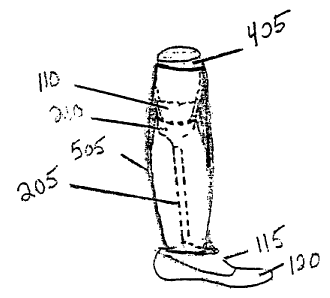
Figure S is side elevational view of a nearly completed prosthesis,
including intermediate components used in an embodiment of a method
of the present invention, and shows the final polymer coating SOS over
the supporting structure, which includes the cast 405, the socket 110,
s socket adapter 210, pylon 205, and keel 115. The foot 120 is show for
reference purposes; it gets permanently attached during the next step.
Preparing the Prosthesis for Bonding of the Foot
Once the plastic has cooled for at least 20 minutes, it is
io disconnected from the primary and secondary vacuums. A cast saw is
used to cut around the perimeter of the socket above the trim lines
exposing the plaster, which is then chiseled out. A belt sander can be
used to reduce the posterior seam to the appropriate size considering
patient weight and activity level. The posterior seam should generally be
is rounded and reduced to 1/32 inch at the top of the popliteal area. On
heavier or more active patients the seam is preferably at least '/4 inch.
The plastic on the bottom of the keel is removed using the belt
sander to expose the two raised segments of foam. The periphery and the
apex of the keel are then roughened with a 36-grit cone on low speed.
zo A rounded edged 7/8-inch spade bit is used to drill through the keel
at the dimple on the bottom until the space in the keel where the pylon
inserts into the keel is reached. Epoxy on the base of the pylon should be
visible at this point. A '/2-inch solid pipe can be used in this hole to drive
the foam pylon, socket adapter and cap from the prosthesis through the
is inside of the socket. The foam in the base of the keel is then hollowed
out using a small acorn bit. It is important to that the diameter of the hole
created by the spade bit is kept as small as possible. A screwdriver may
m
CA 02360845 2001-10-31
assist in removal of the foam. The excess foam is removed from the cap
and the cap replaced in the prosthesis and is wet-glued in place using a
barge cement.
The "skin" is removed from the bottom of keel and a cross pattern
s of cuts no deeper than 3/32 inch is made on all exposed surfaces on the
keel bottom.
Bonding the Foot
With the foot on prosthesis and the assembly on a '/2-inch heel
io wedge the foot and prosthesis are held firmly in place. The area around
the rubber flange encircling the keel is marked and the foot removed.
Methyl ethyl ketone is used to wipe the foot clean, particularly in the well
area, and the foot is allowed to dry.
Epoxy is applied between the foot and the prosthesis, and the
is assembly is placed in a bag and vacuum attached. With the toe flat on the
work surface, the epoxy is allowed to cure.
The above method may also be adapted for transferring a fitting
prosthesis. In this option, a piece of natural copolymer is attached to the
base platform of the vertical alignment jig. The prosthesis that is to be
ao transferred is centered on the platform with a '/2-inch heel wedge under
the heel, and the socket is poured using a pipe with a collar attached and
inserted in the jig. After the plaster has hardened the outline of the foot is
traced on the plastic platform. The height of the collar as it is attached to
the main strut of the vertical alignment jig is noted, the prosthesis is
Zs removed from the jig, and the socket is removed from the cast. The
socket is dropped in 1 /8-inch copolymer and then the complete method
i8
CA 02360845 2001-10-31
above is employed. The alignment must be lengthened 1/2 inch from the
height at which it was poured.
While the above detailed description describes the preferred
embodiments of the present invention, it will be understood that the
s present invention is susceptible to modification, variation and alteration
without deviating from the scope of the fair meaning of the subjoined
claims.
19