Note: Descriptions are shown in the official language in which they were submitted.
CA 02360871 2001-08-02
WO 00/45751 PCT/CHOO/00060
END MEMBER FOR A BONE FUSION IMPLANT
The present invention relates to a device for fusion of bone, particularly
vertebrae,
and in particular to an end member for an implant for fusing bone or
particularly
vertebrae as defined in the preamble of the independent claims 1, 37 and 38.
The treatment and management of bone defects remains one of the most
challenging
aspects of orthopaedics. Bone defects occur in a wide variety of clinical
situations.
Restoring natural anatomical length and shape of any long bone with a bone
defect is
problematic. Additionally, whenever a vertebra has to be removed, it is
necessary to
insert a vertebral spacer to restore the natural length and curvature of the
spine as
well as to promote bone fusion. Restoring spinal anatomy and stability and
promoting bone fusion are even more difficult in a corpectomy, a surgical
procedure
in which a section of one or several vertebrae is removed.
Many different implants have been developed for use with bone defects. So-
called
,.mesh implants" have shown to be particularly effective. One such implant is
the
SynMeshTM available from Synthes (USA) of Paoli, Pennsylvania. The SynMeshT',
is
a titanium mesh cylinder which is provided with a plurality of uniformly-
spaced
apertures of uniform size distributed on its surface. In order to address the
different
clinical situations in which bone defects arise, the SynMeshTM is available in
a variety
of lengths and diameters. Commercially available allografts for treating bone
defects
have recently become available.
Although the clinical results of mesh and allograft implants have generally
been
positive, one possible clinical complication is subsidence of the implant.
Excessive
sinking of the ends of the implant into the bone with which they contact is
especially
troublesome whenever the bone is extremely porous. From both a mechanical and
physiological point-of-view, it would also be advantageous to increase the
surface
contact area between the implant and bone. U.S. Patent No. 5,702,451 to
Biedermann et al. discloses end rings that attempt to address these concerns.
However, the end rings disclosed have no provisions for holding, insertion,
and
distraction instruments. Thus, implantation can be difficult.
WNF1=RMT1ON'`COPY
04-04-2001 ,5/PCT CA 02360871 2001-08-02 CH 000000(
4.4.2001
2
Furthermore, there can be excessive movement between the bone and the
disclosed
end rings after implantation. This may delay, and perhaps prevent bone fusion.
Another implant for fusion of bone, particularly vertebrae consisting of a
multiplicity of
axially mountable members is known from DE 195 09 317 ULRICH. This known
implant comprises two terminal implant members and an intermediate third
implant
member which is rotatable connected about a common axis with the terminal
members. The intermediate member is threadably connected with one terminal
member, such that the length of the implant is adjustable through rotating the
intermediate member.
As the discussion above illustrates, there is a need for an improved end
member for
use with a bone fusion implant.
The invention solves this problem by means of a device for fusion of bone,
particularly vertebrae, and in particular to an end member for an implant for
fusing
bone or particuiariy vertebrae which is characterized by the features of the
claims 1,
37 and 38.
The present invention relates to an end member for use with a bone fusion
Implant
for fusing portions of bone. The end member has a first portion, a second
portion
sized to be inserted into the bore of the implant, and a shoulder between the
first and
second portions. When the second portion Is inserted into the bore, the
shoulder
rests on an edge of the implant. The top surface of the first portion conforms
in size
and shape with the bone and has a channel or multiple channels for receiving a
surgical instrument. When multiple channels are present, all the channels can
run in
the same direction, (e.g. the channels run in the anteroiateral direction), or
the
channels can run in different directions, (e.g. a first channel runs in the
anterior-
posterior direction and a second channel runs in the lateral direction).
If the implant is made of metal, the end member is made of the same material
in
order to resist corrosion. The end member may also be made of allograft bone.
The
end member may have a wedge-shaped or spherical profile to restore the natural
curvature of bone or to correct for a non-orthogonal osteotomy. One way to
create
AMENDED SHEET
FMPFAN6S7FiT 4.APR. 14.54 Au8DRUCKSZEIT 4,APR. 14:56
04-04-2001 CH 0000001
2a
the wedge-shaped profile is to have the first end of the first portion to be
thicker than
the second end.
The top surface can be made in any suitable cross-sectional shape, such as
oval,
oblong, or round, and may be annular or solid. The top surface can be a flat
planar
surface or can have a curvature that mimics the topography of the bone. The
top
surface may be provided with teeth or textured for interlocking with the bone.
The
teeth may have a pyramid or saw tooth shape.
CA 02360871 2001-08-02 AMENDED SHEET
FMPFANSWFiT 4.APR. 14-54 xuSDRUCKSZEIT 4,APR. 14:56
CA 02360871 2001-08-02
WO 00/45751 PCT/CHOO/00060
3
In order to secure the end member to the implant, the second portion may have
a
hole for receiving a fastener. Alternatively, the exterior surface of the
second portion
may have protuberances that are sized to fit within the apertures of the
implant. In
an exemplary embodiment, the second portion comprises a plurality of tabs to
secure
the end member to the implant. These tabs may be resilient so that the tabs
flex
inward upon insertion of the second portion into the implant and flex back
outward to
create a friction fit that secures the end member to the implant. In another
embodiment, the end member includes a projection hinged or pivotably connected
to
the first portion, a threaded bore in the second portion, and a set screw
insertable
into the threaded bore. Threading the set screw into the bore causes outward
movement of the projection to thereby secure the end member to the implant.
In an alternative embodiment, an end member according to the present invention
includes a top surface conforming in size and shape with the bone and a sleeve
extending from the top surface and configured and dimensioned to receive an
end of
the implant. The end member further comprises first and second sections
pivotable
between and open position to facilitate receiving the end of the implant by
the sleeve
and a closed position to secure the end member to the implant. A locking
element
fixes the end member in the closed position.
In another alternative embodiment, the end member includes an outer ring
having a
prong with a ramped surface and an inner ring rotatable with respect to the
outer
ring. The inner ring has a protrusion which contacts the ramped surface of the
prong
upon rotation to thereby urge the prong radially outward.
Preferred features of the present invention are disclosed in the accompanying
drawings, wherein similar reference characters denote similar elements
throughout
the several views, and wherein:
FIG. I shows a perspective view of a first embodiment of an end member
according
to present invention;
FIG. 2 shows a side view of the end member of FIG. 1 inserted into a
cylindrical
CA 02360871 2001-08-02
WO 00/45751 PCT/CHOO/00060
4
mesh implant;
FIG. 3 shows a perspective view of an end member having an oblong shape;
FIG. 4a shows a perspective view of an end member having an oblong shape and
teeth for improving implant stability;
FIG. 4b shows a perspective view of an end member having first and second
channels for facilitating use with implantation instrumentation;
FIG. 4c shows a perspective view of another embodiment of an end member having
first and second channels;
FIG. 5 shows a side view of an end member having a wedge-shape profile;
FIG. 6 shows a perspective view of an end member having protuberances for
fixation
to the implant;
FIG. 7 shows a perspective view of a non-annular end member;
FIG. 8 shows a perspective view of the bottom of an end member according to
the
present invention;
FIG. 9 shows a perspective view of the bottom of an end member according to
the
present invention;
FIG. 10 shows a top view of another embodiment of the end member according to
the present invention;
FIG. 11 shows a cross-sectional view of the end member of FIG. 10;
FIG. 12 shows a top view of another embodiment of the end member according to
the present invention;
CA 02360871 2001-08-02
WO 00/45751 PCT/CHOO/00060
FIG. 13 shows the end member of FIG. 12 secured to a cylindrical mesh implant;
and
FIG. 14 shows a cross-sectional view of another embodiment of the end member
according to the present invention.
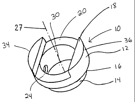
FIG. 1 shows a first embodiment of an end member 10 according to the present
invention. End member 10 has a first portion 12 and a second portion 14. As
first
portion 12 is larger than second portion 14, a shoulder 16 is formed at the
intersection between first and second portions 12, 14. A top surface 18 of
first
portion 12 is provided with a first channel 20 for accommodating surgical
instrumentation such as holding, insertion, and/or distraction instruments.
Top
surface 18 is shown in FIG. 1 with a round shape. However, as will be evident
from
the other embodiments, top surface 18 can have any suitable shape. Preferably,
top
surface 18 has a shape that matches the shape of the bone it will contact.
Second portion 14 is also shown having a round shape. As was the case for top
surface 18, second portion 14 can have any suitable shape. Preferably, the
shape of
second portion 14 matches the shape of the bone fusion implant used with the
end
member. As best seen in FIG. 2, second portion 14 is sized and shaped to be
inserted into the inner bore of a bone fusion implant 22 so that shoulder 16
rests on
bone fusion implant 22. Bone fusion implant 22 can be a number of different
implant
types, including, for example, a mesh implant, an allograft implant, or any
metallic or
non-metallic implant. If implant 22 is made of a metallic material, end member
10 is
preferably made of the same metallic material or a non-metallic material to
avoid
mixed-metal (galvanic) corrosion. End member 10 can also be made of allograft
bone from cancellous bone, cortical bone, a combination of cancellous and
cortical
bone, or a composite of cancellous and cortical bone. After implantation of
end
member 10 and bone fusion implant 22, physiological compressive forces will
tend to
hold end member 10 in place against bone fusion implant 22. However, to
provide
further stability as well as to facilitate pre-operative and intra-operative
handling,
second portion 14 can be secured to bone fusion implant 22. For example,
second
portion 14 can be press-fit or snap-fit into bone fusion implant 22.
Additionally,
because bone fusion implant 22 is typically deformable, bone fusion implant 22
can
CA 02360871 2001-08-02
WO 00/45751 PCT/CHOO/00060
6
be crimped to end member 10. Second portion 14 can also be provided with a
hole
24 for receiving a fastener such as a pin or a screw. End member 10 is
inserted into
bone fusion implant 22 so that hole 24 aligns with one of apertures 26 on bone
fusion
implant 22. Hole 24 can extend either partially or completely through second
portion
14 and can be threaded. As shown in FIG. 6, second portion 14 can
alternatively
have protuberances 28 that are sized to fit in apertures 26 for mechanically
securing
the end member to the bone fusion implant. Other exemplary mechanisms for
securing the end member to the bone fusion implant are described in more
detail
below.
Referring back to FIGS. 1 and 2, the surface area of top surface 18 is greater
than
the surface area of the top and bottom surfaces of bone fusion implant 22.
Because
of this greater surface area, there is more contact area between top surface
18 and
the surrounding bone than there would be for the top and bottom surfaces of
implant
22. The increase in contact area helps to resist subsidence of implant 22. The
increased contact area has other benefits such as greater load sharing between
end
member 10 and the surrounding bone. Top surface 18 is shown as a ring with an
annular space 30. New bone can form in annular space 30 to promote fusion.
Annular space can be filled with bone chips or any other osteoinductive or
osteoconductive material to promote the formation of bone.
Alternatively, as shown in FIG. 7, top surface 18 can be a solid surface to
maximize
contact area between top surface 18 and the surrounding bone. A solid top
surface
18 would be desirable in clinical situations in which subsidence is especially
a
concern.
FIG. 3 shows a second embodiment of an end member 110 according to the present
invention. In general, most of the structure of end member 110 (as well as the
embodiments described below) is like or comparable to the structure of end
member
and, accordingly the same reference numeral is used for like components and
discussion of those like components is not believed necessary. End member 110
has an oval or oblong shape and would be used in situations in which the
surrounding bone (and consequently the bone fusion implant) is substantially
oval or
oblong. When the end member has a non-symmetrical shape like end member 110,
CA 02360871 2001-08-02
WO 00/45751 PCT/CHOO/00060
7
first channel 20 can be provided in any orientation. For example, first
channel 20 is
shown running along the long axis of end member 110, but could run in any
direction
to be oriented differently with respect to the surrounding bone. The
variability in the
placement of first channel 20 means that first channel 20 can be positioned as
best
suited for the particular surgical approach that is being used. Specifically,
if end
member 110 is being implanted with the short axis in the anterior/posterior
direction,
then first channel 20 is ideal for a lateral surgical approach. If an anterior
or posterior
approach is anticipated, then first channel 20 should run in the anterior-
posterior
direction.
FIG. 4a shows an end member 210 with first channel 20 running at an angle with
respect to the long axis of end member 210. This direction of first channel 20
is
preferred for an anterolateral surgical approach, which can be used in spinal
surgery.
FIG. 4b shows an end member 212 that includes first and second channels 20,
21,
both running at an angle with respect to the long axis of end member 212.
Preferably, first and second channels 20, 21 are symmetrically placed with
respect to
the long axis of end member 212. Providing end member 212 with both first and
second channels 20, 21 allows at least one of first and second channels 20, 21
to be
accessed during implantation regardless of whether the left or right side is
used for
the anterolateral surgical approach. Furthermore, the arrangement of channels
20,
21 allows one end member to be used on each end of bone fusion implant and
still
have the channels on the top end member align with channels on the bottom end
member. FIG. 4c shows an end member 214 that also includes first and second
channels 20, 21. First channel 20 runs parallel to the long axis of end member
214
and second channel 21 runs transverse to the long axis of end member 214.
Including both first and second channels 20, 21 on end member 214 provides
access
to at least one of first and second channels 20, 21 regardless of the
implantation
orientation of end member 214 or the surgical approach.
For each of the end members shown in FIGS. 4a, 4b, and 4c, top surface 18 has
a
plurality of teeth 32 which provides a mechanical interlock between the end
member
and the surrounding bone. Teeth 32 provide the mechanical interlock by
penetrating
the bone. The initial mechanical stability afforded by teeth 32 minimizes the
risk of
post-operative pullout or expulsion of the end member. Teeth 32 can have any
CA 02360871 2001-08-02
WO 00/45751 PCT/CHOO/00060
8
suitable configuration such as pyramid-shaped, saw-tooth shaped, etc.
Alternatively,
top surface 18 can be textured to provide the mechanical interlock between the
end
member and the surrounding bone.
As seen in FIG. 5, an end member 310 has a wedge profile. A wedge profile
would
be useful in spinal applications in order to restore the natural curvature of
the spine
or any bone. A wedge profile would also be useful to compensate for a non-
perpendicular osteotomy cut dictated by the pathology, clinical situation, or
erroneously made to remove bone. It should be noted that as an end member
would
ordinarily be used on each end of bone fusion implant, end members having
different
wedge profiles can be used together. One way to achieve this wedge shape
results
from a gradual decrease in thickness in first portion 12 from a first end 34
to a
second end 36 so that top surface 18 has a slope defined by angle a. In FIG.
5, top
surface 18 is shown as a flat planar surface. However, top surface 18 can be a
curved surface and still retain the wedge-shaped profile. As the curve can be
made
to be a mirror-image of the topography of the vertebral end plates, a curved
top
surface 18 would conform to the contours of the vertebral end plates.
As previously discussed, FIG. 6 shows an end member 410 that is provided with
protuberances 28 sized to fit in apertures 26 of bone fusion implant 22 (FIG.
2). FIG.
7, which has also been discussed, shows an end member 510 having a solid top
surface 18 that is preferably used when there is a higher incidence of
subsidence.
FIG. 8 shows an end member 610 that has a second portion 14 that includes a
plurality of tabs 40 for securing end member 610 to bone fusion implant 22. In
one
embodiment, tabs 40 are resilient so that as second portion 14 of end member
610 is
pushed into bone fusion implant, tabs 40 flex inward and then back outward to
secure end member 610 to bone fusion implant 22. As bone fusion implant 22 has
some elasticity which would allow it to flex outward to accept tabs 40, tabs
40 need
not be resilient. The number, size, and arrangement of tabs 40 can be varied.
FIG.
9 shows an end member 710 that is similar to end member 610 except for the
overall
change in shape (from round to oval or oblong).
FIGS. 10 and 11 show an end member 810 that has another mechanism for securing
CA 02360871 2001-08-02
WO 00/45751 PCT/CHOO/00060
9
end member 810 to bone fusion implant 22. Specifically, end member 810 is a
cap
that sits on top of implant 22. End member 810 includes a top surface 812
conforming in size and shape with the bone and a sleeve 814 extending from top
surface 812. Sleeve 814 is configured and dimensioned to receive a portion of
implant 22. In order to facilitate insertion and removal of end member 810
from
implant 22, end member 810 is preferably made in two sections 816, 818. In an
exemplary embodiment, sections 816, 818 are pivotably connected at a pivot 820
so
that sections 816, 818 can be separated, i.e. end member 810 opens. End member
810 also includes a locking mechanism for keeping the two sections 816, 818 in
contact. In one embodiment, this locking mechanism comprises a first serrated
edge
822 that cooperates with a second serrated edge 824.
FIGS. 12 and 13 show an end member 910 that includes inner and outer rings
912,
914. Inner ring 912 can be rotated relative to outer ring 914. Inner ring 912
has
means for receiving a tool to rotate inner ring 912 (shown as holes 916 that
accept
prongs of the tool). Inner ring 912 also has a pair of protrusions 918 that
cooperate
with flexible prongs 920 located on outer ring 914. As inner ring 912 is
rotated,
protrusions 918 contact prongs 920 and force prongs 920 out in a radial
direction.
When end member 910 is fitted in implant 22, the outward radial movement of
prongs
920 causes prongs 920 to press against implant 22 to secure end member 910 to
implant 22.
FIG. 14 shows an end member 950 in which second portion 14 includes at least
one
projection 952. Projection 952 is pivotably connected to second portion 14 at
junction 953 so that as a set screw 954 is screwed into threaded bore 956, set
screw
954 causes outward movement of projection 952. This outward movement secures
end member 950 to implant 22. Junction 953 preferably has a reduced cross
section
compared to the rest of projection 952 so that the flexing caused by set screw
954
occurs in junction 953.
While various descriptions of the present invention are described above, it
should be
understood that the various features can be used singly or in any combination
thereof.
CA 02360871 2001-08-02
WO 00/45751 PCT/CH00/00060
Therefore, this invention is not to be limited to only the specifically
preferred
embodiments depicted herein.
Further, it should be understood that variations and modifications within the
scope of
the invention may occur to those skilled in the art to which the invention
pertains.
Accordingly, all expedient modifications readily attainable by one versed in
the art
from the disclosure set forth herein that are within the scope and spirit of
the present
invention are to be included as further embodiments of the present invention.
The
scope of the present invention is accordingly defined as set forth in the
appended
claims.