Note: Descriptions are shown in the official language in which they were submitted.
CA 02361155 2001-08-13
WO 00/51712 PCT/US99/14804
FILTER SUPPORT, ASSEMBLY AND SYSTEM
The present invention pertains to filter supports, filter assemblies,
including filter
supports and powered air purifying respirators, including helmets in which
filter assemblies
including filter supports are mounted.
Background
Respirators that filter air for breathing are frequently worn when individuals
work in
areas where air may be contaminated with toxic or noxious substances.
Filtering
respirators may operate under negative pressure, in which inhalation by the
wearer draws
air through the filter, or they may operate using positive pressure, in which
a fan or other
device supplies air to a wearer. A powered air purifying respirator (PAPR)
typically
includes a motor blower unit, a filter, and a power source (e.g., a battery
pack). In some
systems, these components reside on a belt around the waist of a user, with a
tube
conveying the purified air to a facemask, hood, helmet, etc. Belt or back-
mounted
equipment may, however, be subject to disengagement from the wearer during use
and/or
may also reduce the ability of the wearer to work in tight spaces.
Some PAPRs, such as the AIRSTREAMTM and AIRHATTM (3M Company, St.
Paul, Minnesota), house these components inside a helmet to avoid the need to
mount
components on the user's back or belt. It is advantageous to locate the filter
in helmet-
mounted PAPRs within the crown space between the wearer's head and the
helmet's outer
shell. Locating the filter within the crown space can help to reduce the
profile or size of the
helmet as compared to helmet-based systems in which the filter is located
outside of the
crown space. Helmets with smaller profiles are desirable because they allow
the wearer to
work in smaller, tighter spaces than helmets with larger profiles.
Powered air purifying respirator performance is measured by parameters such as
airflow, pressure drop across the filter during operation, efficiency in
removing
contaminants, and particulate loading capacity. Airflow and pressure drop are
related
because, for a given blower and power source, a filter with a smaller pressure
drop will
deliver higher airflow. Conversely, a filter with a larger pressure drop will
deliver lower
airflow using the same blower and power source. Airflow and pressure drop are
important
1
CA 02361155 2001-08-13
WO 00/51712 PCT/US99/14804
because, to provide the same amount of filtered air, a respirator system with
a higher
pressure drop filter requires more energy than a respirator system with a
lower pressure
drop filter.
Pressure drop for a given airflow rate across a filter can be decreased by
increasing
the openness or looseness of the filter material. A filter in which the
openness or looseness
of the filter material is increased, however, typically exhibits reduced
efficiency in removal
of contaminants, which is another one of the parameters by which powered air
purifying
respirator system performance is measured. Pressure drop for a given airflow
rate can also
be reduced without decreasing the efficiency of contaminant removal by
increasing the size
or surface area of the filter. Increasing the filter size, however, typically
also includes
increases in the size and/or bulk of the system. Such increases in size and/or
bulk of the
filter can increase the profile or size of helmet-mounted PAPRs, thereby
potentially limiting
the wearer's mobility in confined areas.
Helmet-mounted and other powered air purifying respirator systems used in
connection with dust/mist filters have included filter bag holders that
support the dust/mist
filter bag inlet and/or the perimeter of the dust/mist filter bag. One such
respirator system
is disclosed in, e.g., U.S. Patent No. 4,280,491 (Berg et al.). The dust/mist
filter bag
holders typically provide only limited or no support through the center of the
dust/mist
filter bag because the airflow alone was sufficient to prevent kinking of the
dustlmist filter
bag materials.
Another filter support used in some helmet-mounted respirators is illustrated
in
FIG. 1. The filter bag holder 110 is designed to support a flat dust/mist
filter bag in an
arcuate form to fit within the crown of a helmet. The holder 110 is
constructed of two
members 112 and 114, with the smaller member 114 being held in compression to
provide
an opening 116 between the two members at one end thereof. Both members 112
and 114
include a plurality of openings 118 and 120, respectively, that are aligned
along the length
of the holder 110.
The filter bag holder 110 is manufactured of relatively flexible thermoformed
polystyrene and is designed to allow a filter bag to billow outward from the
filter support
during operation. In other words, the filter bag holder 110 is designed
primarily to
maintain the filter bag in an arcuate shape.
2
CA 02361155 2001-08-13
WO 00/51712 PCT/US99/14804
New regulations promulgated by the National Institute of Occupational Safety
and
Health (NIOSH) for powered air purifying respirators, require the respirators
to use High
Efficiency Particulate Air (HEPA) class filters that remove 99.7% of a test
aerosol. See 42
C.F.R. 84 (1995). To provide that level of contaminant removal efficiency,
however, the
filter materials used are typically significantly stiffer and/or heavier than
the filter materials
used in lower efficiency dust/mist filters.
Filters that provide HEPA class efficiency in helmet-mounted powered air
purifying
respirators can be provided in relatively rigid pleated media. When the
pleated filters are
located in a helmet's crown space, the pleated filter media are typically
arcuately shaped as
seen in, e.g., U.S. Patent No. 4,462,399 (Braun). Shaped, pleated filters
typically include
the desired filter material along with the support structure required to
maintain the shape of
the pleats. The additional components increase the filters' cost and also
typically increase
the filters' bulk, resulting in higher shipping and storage costs. The helmet
used with
pleated filters may also be larger, thereby increasing the profile and
limiting the wearer's
maneuverability in confined spaces.
As compared to shaped pleated filters, filter bags are typically less
expensive to
manufacture, and are also less expensive to ship and store due to their
smaller size. When
used in connection with helmet-mounted respirators in which the filter bag
must be
arcuately-shaped to fit within a helmet crown, however, the stiffer material
in flat HEPA
class filter bags may tend to kink. Filter bag kinking may be particularly
severe if the
HEPA class filter bag is supported only about its perimeter as with some known
filter bag
holders.
Kinking creates flow obstructions that can reduce filter bag performance by
increasing the pressure drop across the filter which can, in turn, reduce the
airflow rates of
the respirator system using the kinked filter bag. Filter bag kinking can also
reduce the
filter's effective area which, in turn, can also reduce the filter particulate
loading capacity.
As discussed above, particulate loading capacity is another one of the
parameters by which
filter performance is judged. Kinked filter bag areas are not evenly loaded
with particulate
matter during use, thereby reducing filter bag particulate loading capacity.
The filter bag holder 110 of FIG. 1 is another example of known filter bag
holder
designed for use with dust/mist filter bags and is typically incapable of
preventing kinking
3
CA 02361155 2006-11-01
60557-6570
of HEPA class filter bags. In addition, the holder 110 is
formed of members that have relatively large surface areas.
Those large surface area members can effectively block
airflow to large areas of the filter, thereby increasing
pressure drop and reducing particulate loading capacity.
Summary of the Invention
In brief summary, the present invention provides,
in one aspect, a filter support comprising: two or more
first support ribs on a first side of the filter support,
each of the first support ribs being generally aligned with
a longitudinal axis of the filter support; and two or more
second support ribs on a second side of the filter support,
the second side being opposite the first side of the filter
support and each of the second support ribs being generally
aligned with the longitudinal axis; wherein at least one of
the first support ribs is laterally offset from each of the
second support ribs along a transverse axis that is
transverse to the longitudinal axis such that airflow is
allowed to distribute crosswise in addition to lengthwise
through the filter support.
The filter support provides support to opposing
sides of a filter bag or opposing individual filter
elements. By laterally offsetting the first and second
support ribs relative to each other across the width of the
filter support, airflow across the filter support's width is
not as inhibited as it would be if the first and second
support ribs were substantially aligned with each other. As
a result, loading capacity may be improved because more of
the filter material in a filter assembly including the
filter support can be loaded with filtrate. In addition,
pressure drop across a filter assembly using the filter
4
CA 02361155 2006-11-01
60557-6570
support can be improved because of reduced flow restrictions
provided by the laterally offset support ribs.
The present invention also provides, in other
aspects, a filter assembly including a filter and a filter
support as discussed above, along with a helmet-mounted
powered air purifying respirator in which the filter
assembly is located within the helmet crown.
Because the filter support of the invention
includes support ribs that preferably separate and support
the central portion of a filter bag in addition to its
perimeter, the filter support may advantageously reduce or
prevent kinking of a flat filter bag that must be arcuately
shaped for use in a respirator system. This advantage may
be most apparent when the filter bags are constructed of
HEPA class filter material.
4a
CA 02361155 2001-08-13
WO 00/51712 PCT/US99/14804
These and other features and advantages of the invention are described with
respect
to various illustrative embodiments of the invention below.
Glossary
In reference to the invention, the following terms are defined as set forth
below:
"crown space" means the space between a wearer's head and the concave side of
a
helmet having a crown;
"filter" or "filter material" mean a generally porous device or material
designed to
entrap or remove particulates, liquids, and/or gases from an airstream;
"filter bag" means a bag formed at least partially of filter material;
"filter support" means a device that maintains separation between opposing
sides of
a filter bag or between two opposing filter elements;
"generally aligned with the longitudinal axis" means that the support ribs
progress
along the longitudinal axis when moving from the input end of the filter
support to the
terminal end of the filter support.
"HEPA class" and "High Efficiency Particulate Air class" define the
performance of
filter material as set forth in 42 C.F.R. 84 (1995)
"laterally offset" means that the referenced structures are not aligned with
each
other along the relevant axis;
"longitudinal axis" means an axis that extends generally along the length of a
filter
support;
"support rib" means a structural member designed to support at least a portion
of a
filter; and
"transverse axis" means an axis that extends generally perpendicular to the
longitudinal axis.
Brief Description of the Drawings
FIG. 1 is a perspective view of a prior art arcuate filter bag holder 110.
FIG. 2 is a perspective view of one filter support according to the present
invention.
FIG. 3 is a side view of the filter support 10 depicted in FIG. 2.
5
CA 02361155 2001-08-13
WO 00/51712 PCTIUS99/14804
FIG. 4 is a cross-sectional view of the filter support 10 taken along line 4-4
in FIG.
3.
FIG. 5 is a plan view of the filter support 10.
FIG. 6 is a side view of the filter support 10 located in a filter bag 40
which is
depicted in a partial cross-sectional view.
FIG. 6A is an enlarged cross-sectional view of one HEPA class filter material
42
useful in connection with the present invention.
FIG. 7 is a side view of the filter support 10 and filter bag 40 located
within a
helmet 50 used in connection with a powered air purifying respirator.
FIG. 8 is a plan view of another filter support 210 according to the present
invention.
FIG. 9 is a side view of the filter support 210 of FIG. 8.
FIG. 10 is a plan view of another filter support 310 according to the present
invention.
FIG. 11 is a plan view of another filter support 410 according to the present
invention.
FIG. 12 is a side view of the filter support 410 of FIG. 11.
FIG. 13 is an enlarged side view of one alternative support rib 420' for use
in a
filter support.
FIG. 14 is a side view of a filter support 410' including support ribs 420' as
illustrated in FIG. 13.
FIG. 15 is a plan view of a filter support 510 according to the present
invention.
FIG. 16 is a side view of the filter support 510 of FIG. 15.
FIG. 17 is a side view of one support member 560d of the filter support 510 of
FIGS. 15 and 16.
Detailed Description of Illustrative Embodiments
Although the filter supports of the present invention may provide particular
advantages when used in connection with helmet-mounted powered air purifying
respirators, the filter supports may also be used in other systems or
applications in which
the opposing sides of filter bags must be separated without significantly
restricting flow
6
CA 02361155 2006-11-01
60557-6570
within the filter bag. In addition, the filter supports may
also be used in connection with systems in which separation
must be maintained between opposing filter elements.
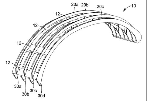
FIGS. 2-5 depict one illustrative embodiment of a
filter support 10 of the present invention having a length
along a longitudinal axis 11 and a width along an axis 13
that is transverse to the longitudinal axis 11. Filter
support 10 includes a plurality of support ribs 20a, 20b and
20c located on one side thereof. The support ribs 20a-20c
preferably extend along the length of the support 10 from a
first end 32 to a second end 34. Also seen in FIG. 2 are a
plurality of second support ribs 30a, 30b, 30c and 30d
located on the opposite side of the support 10. Second
support ribs 30a-30d also preferably extend over
substantially the entire length of the filter support 10. A
plurality of cross-supports 12 are located at spaced
intervals along the filter support length and preferably
extend across the width of the filter support 10. The
cross-supports 12 preferably maintain spacing between the
first support ribs 20a-20c and second support ribs 30a-30d.
The filter support 10 preferably has an arcuate
shape and extends from an input end 14 to an terminal end
16. The arcuate shape is particularly preferred when the
filter support 10 is to be used in connection with helmet-
mounted powered air purifying respirators. The increasing
height of the second support ribs 30a-30d at the input end
14 of the filter support 10 can be seen in, e.g., FIGS. 2
and 3. The height increase at the filter support input end
14 may reduce or prevent filter material kinking at the
input end 14.
7
CA 02361155 2006-11-01
60557-6570
It is also desirable to reduce the frontal area of
the filter support 10 along the length of the filter support
by minimizing the thickness of the structural components,
such as the first support ribs 20a-20c, second support ribs
5 30a-30d and cross-supports 12.
As seen in FIG. 4, filter support 10 includes
first support ribs 20a, 20b and 20c on a first side of the
filter support 10 and second support ribs 30a, 30b, 30c, and
30d on a second side of the filter support. Both sets of
10 support ribs 20a-20c and 30a-30d are spaced across the
filter support width. At least one of the first support
ribs 20a-20c on the first side is laterally offset across
the width of the filter support 10 from the second support
ribs 30a-30d on the second side. It may be preferred,
however, that all of the first support ribs 20a-20c are
laterally offset from all of the second support ribs 30a-
30d, as illustrated in FIG. 4.
7a
CA 02361155 2001-08-13
WO 00/51712 PCTIUS99/14804
By providing laterally offset support ribs on each side of the filter support
10,
airflow is allowed to distribute crosswise in addition to lengthwise through
the filter
support 10. If the first support ribs 20a-20c were aligned with the second
support ribs 30a-
30d, the support ribs could create lengthwise channels. Airflow through the
filter support
10 could then be restricted to substantially lengthwise movement along the
channels, which
may result in uneven flow distribution within the filter support. That uneven
flow
distribution may result in uneven particulate loading, which could limit the
overall or
ultimate particulate loading capacity of a filter bag located over filter
support 10. The
uneven flow caused by aligned support ribs would also likely increase pressure
drop across
a filter bag located over the filter support 10.
FIG. 4 illustrates another preferred feature of the present invention in that
the
outermost second support ribs 30a and 30d are shorter than the second support
ribs 30b
and 30c located between the outermost support ribs 30a and 30d. The reduced
height of
the outermost support ribs 30a and 30d may be particularly useful when the
filter support
10 is used in connection with flat filter bags because the filter bag sides
are typically joined
in the area of the outermost support ribs 30a and 30d, thereby narrowing the
bag. By
reducing the outermost support rib height, stress on a flat filter bag's seams
may be
reduced.
Another preferred feature illustrated in FIG. 4 is the relative number of
support ribs
on either side of the filter support 10. The number of second support ribs 30a-
30d on the
concave second side of the preferred arcuate filter support 10 is preferably
greater than the
number of first support ribs 20 on the convex side of the preferred arcuate
filter support 10.
The support's concave side preferably includes more support ribs 30a-30d than
the convex
side on which first support ribs 20a-20c are located. More support ribs 30a-
30d are
preferred on the concave side to prevent kinking of the concave side of a
filter bag located
on the preferred arcuate support 10. As discussed above, filter bag kinking
can limit flow,
increase pressure drop and cause uneven particulate loading.
FIG. 5 illustrates a plan view of the filter support 10 including a
longitudinal axis 11
and a second transverse axis 13. Axis 13 is transverse to the longitudinal
axis 11, meaning
that the transverse axis 13 is generally perpendicular to the longitudinal
axis 11. The first
support ribs 20a-20c and second support ribs 30a-30d are preferably aligned
with the
8
CA 02361155 2001-08-13
WO 00/51712 PCTIUS99/14804
longitudinal axis 11. Although the support ribs 20a-20c and 30a-30d are
preferably aligned
with longitudinal axis 11, they may exhibit slight variations in that
alignment where such
variations occur will not substantially affect airflow through the filter
support 10. Cross-
supports 12 illustrated in FIG. 5 are preferably distributed over the filter
support length to
maintain proper spacing between the support ribs 20a-20c and 30a-30d. The
cross-
supports 12 are optional, i.e., not every filter support may include them.
Although the illustrated cross-supports 12 are oriented generally transverse
to the
longitudinal axis 11, it should be understood that they need not necessarily
be transverse to
the longitudinal axis 11. Furthermore, although cross-supports 12 do extend
across the
width of the filter support 10 as seen in FIG. 5, cross-supports in other
filter holders may
extend only partially across the filter support width.
Filter supports 10 according to the present invention may be manufactured by a
variety of techniques. It may be preferred to manufacture the filter supports
of a moldable
material using, e.g., injection molding techniques. Those skilled in the art
will, however,
envision many other ways in which filter supports according to the present
invention could
be manufactured.
FIG. 6 illustrates filter support 10 located within a filter bag 40. Preferred
filter
bags 40 used in connection with the filter support 10 are manufactured as flat
filter bags.
Flat filter bags are preferred because they are less expensive to manufacture
than a shaped
bag. Furthermore, with the addition of a separate filter support 10, as
described above, the
need for a shaped filter bag is reduced.
The filter support 10 is preferably more rigid than the filter bag 40 in which
the filter
support 10 is used. In other words, the filter bag 40 conforms to the shape of
the filter
support 10. The rigidity may facilitate insertion of the preferred arcuate
filter support 10
and filter bag 40 into the crown space of a helmet.
The rigidity of the filter support 10 may also assist in maintaining
separation
between the opposing sides of the filter bag 40, even filter bags constructed
of stiff HEPA
class filter media. One preferred HEPA class filter media 42 is illustrated in
the enlarged
partial cross-sectional view of FIG. 6A.
The illustrated filter media 42 includes an innermost protective layer 44 of,
e.g., a
plastic mesh netting to protect the inner layers of the filter media 42 during
filter support 10
9
CA 02361155 2006-11-01
60557-6570
insertion. The openings in the netting are preferably large
enough to prevent caking on the netting itself during filter
use. In one example, the netting is about 250 micrometers
thick and includes strands forming diamond shaped openings,
with about 3-6 strands per centimeter.
A coarse filter layer 46 is located above the
protective layer 44 in FIG. 6A and is preferably provided to
entrap larger particulate matter. In one example, the
coarse filter layer 46 is a lower density non-woven of
electret charged fibers marketed under the trade name
FILTRETETM G150 by Minnesota Mining and Manufacturing
Company, St. Paul, Minnesota.
Two layers 48a and 48b of a high efficiency
filtration medium are provided above the coarse filter layer
46. Layers 48a and 48b may preferably be polypropylene
based blown microfiber (BMF) webs as prepared according to
methods described in U.S. Patent 6,123,752. Those methods
use a melt blowing process similar to that described in, for
example, Wente, "Superfine Thermoplastic Fibers", Industrial
Engineering Chemistry, Vol. 48, pp. 1342 et seq. (1956) or
in Report No. 4364 of the Naval Research Laboratories,
published May 25, 1954, entitled "Manufacture of Superfine
Organic Fibers" by Wente et al. The relatively low basis
weight was obtained by increasing the rotational speed of
the collector rather than reducing the resin delivery rate.
The BMF webs could be charged using a hydro-charging process
substantially as described in U.S. Patent No. 5,496,507
(Angadjivand et al.) using a water pressure of about
550 kPa. One suitable resin is Fina 3960, a 350 melt flow
index polypropylene resin available from Fina Corp.,
Houston, Texas.
CA 02361155 2006-11-01
60557-6570
A charge enhancement package for the BMF webs
could be prepared by the following method. Melt compounding
CHIMASSORBTM 944FL (a hindered amine available from Ciba-
Geigy Corp., Hawthorne, New York) into poly(4-methyl-l-
pentene) (TPX DX 820, available from Mitsui Petrochemical
Industries, Tokyo, Japan) in a single screw extruder in a
40:60 ratio and extruding the resultant blend into a large
diameter fiber. Grinding the large diameter fiber into a
powder (0.125 inch mesh) and adding the ground fiber to the
polypropylene pellet feed during preparation of the BMF
webs. The BMF web composition could consist of 98 wt. %
polypropylene and 2% of the charge enhancement package.
l0a
CA 02361155 2001-08-13
WO 00/51712 PCTIUS99/14804
If prepared as discussed above, each of the layers 48a and 48b preferably has
a
thickness of about 0.3 mm, a basis weight of about 22 grams per meter and
include fibers
with an effective fiber diameter of 4.8 micrometers. When tested with a 0.3
micrometer
DOP aerosol at a flow rate of 85 liters per minute, each of the layers 48a and
48b
preferably exhibits a pressure drop of 5.5 mm of H20 and penetration of 0.03%.
The layers 48a and 48b are protected by a cover web 49 over the outside of the
filter bag 40. One preferred cover web is a spun-bond nonwoven polypropylene
and is
chosen such that it provides the desired protection to the underlying filter
layers without
significantly reducing airflow through the filter 40.
All of the materials used in the filter 40 are preferably compatible with the
desired
technique used to bond the sides of the filter, e.g., ultrasonic welding,
adhesive bonding,
etc.
Examples of other filter materials that may be used in connection with the
present
invention are described in U.S. Patent Nos. 4,592,815 (Nakao); 5,496,507
(Angadjivand et
al.); 4,588,537 (Claase et al.); 4,375,718 (Wadsworth et al.); 4,215,682
(Kubik et al.);
5,057,710 (Nishiura et al.); Re 30,782 & Re 31,285 (both to van Turnhout).
The preferred arcuate filter support 10 imparts that arcuate shape to the
filter bag
40 located over the filter support 10. The arcuate filter support 10 and
associated filter bag
40 can be located within the crown of helmet 50, as illustrated in FIG. 7.
Locating a filter
within a helmet crown provides a number of advantages, as discussed in, for
example, U.S.
Patent Nos. 4,280,491 (Berg et al) and 4,462,399 (Braun). Briefly, however,
the use of the
crown space in a helmet-based powered air purifying respirator can reduce the
helmet
profile as compared to helmet-mounted systems that do not use the crown space
while also
eliminating the need for belt or back-mounted blowers and/or power packs.
A further advantage in locating the arcuate filter support 10 and filter bag
40 within
the helmet crown is the potential improvement in the helmet's ability to
absorb impacts.
When used in connection with some helmets, the filter support 10 may
distribute the energy
of an impact over a longer time period, thereby reducing the peak impact force
experienced
by a helmet wearer.
To facilitate impact absorption by the filter support 10, it may be preferred
that the
filter supports 10 be constructed of materials that provide good energy
absorption = and
11
CA 02361155 2006-11-01
60557-6570
impact deflection characteristics over a wide temperature
range. One such material is a blend of high density
polyethylene and a thermoplastic elastomer. In one specific
example, high density polyethylene was blended with a
thermoplastic elastomer (10% by weight) to produce a filter
support 10 that was particularly effective at reducing the
peak impact forces experienced by a helmet wearer over a
broad temperature range. The particular thermoplastic
elastomer used is marketed under the trade name ENGAGE
available from Dow Chemical Corp.
FIGS. 2-7 illustrate one embodiment of a filter
support of the present invention and its use within a helmet
mounted powered air purifying respiration system. FIGS. 8-
17 illustrate alternative filter supports according to the
present invention. Although the supports illustrated in
FIGS. 8-17 are flat, i.e., not arcuate, they could
alternatively be provided in an arcuate form for use in,
e.g., a helmet crown space.
More specifically, FIGS. 8 and 9 illustrate a
filter support 210 including first curved support ribs
220a-220c and second curved support ribs 230a-230c. All of
the support ribs are generally sinusoidal in shape as seen
in the plan view of FIG. 8. The first support ribs
220a-220c are preferably attached to the second support ribs
230a-230c at the points of intersection. As a result, no
separate cross-supports are provided. One such point of
intersection is designated by reference numeral 222 in
FIG. 8. Because the first support ribs 220a-220c and second
support ribs 230a-230c have heights that are less than the
full height of the support 210 (see FIG. 9), openings across
12
CA 02361155 2006-11-01
60557-6570
the width of the support 210 are maintained (where the width
is transverse to the longitudinal axis 211).
FIG. 10 is a plan view of another filter support
310 including first support ribs 320 on one side of the
filter support 310 and second support ribs 330 on the
opposite side of the support 310. The width of the support
310 as measured transverse to the longitudinal axis narrows
from the input end 314 to the terminal end 316 of the
support 310. Cross-members 312 are provided to maintain
proper spacing between all of the support ribs 320 and 330.
FIGS. 11 and 12 illustrate another filter support
410 including angled first support ribs 420a-420h on one
side of the filter support 410 and longer second support
ribs 430 on the opposite side of the filter support 410.
The longer second support ribs 430 preferably extend
substantially the entire length of the support 410 along the
longitudinal axis 411. The filter support 410 also includes
cross members 412 that preferably extend across the width of
the support 410 transverse to the longitudinal axis 411.
Each pair of angled first support ribs 420a/420b,
420c/420d, 420e/420f, 420g/420h are preferably oriented such
that the distance between the support ribs across the width
of the filter support 410 decreases along the length of the
filter support 410 when moving from the input end 414 to the
terminal end 416. Except for the pair of support ribs
420g/420h, it is preferred that each pair of support ribs
does not meet but, instead, provides an opening through
which air can pass along the length of the filter support
410.
13
CA 02361155 2006-11-01
60557-6570
A variation in the filter support 410 of FIGS. 11
and 12 is depicted in FIGS. 13 and 14. One of the angled
support ribs 420b' is illustrated in FIG. 13 and includes a
stepped shape such that the lower support rib portion 422b'
lies within the area occupied by the second support ribs
430' in filter support 410' as seen in FIG. 14. The upper
portions 424b', 424d', 424f', and 424h' of the support ribs
420b', 420d', 420f' and 420h', are, respectively, however,
located on the upper side of the filter support 410'. This
variation may further improve airflow distribution within
the filter support 410'.
The filter supports depicted in FIGS. 8, 10 and 11
illustrate variations in one feature of all filter supports
manufactured according to the present invention, i.e.,
support ribs that are generally aligned with a longitudinal
axis. As indicated above in the glossary, "generally
aligned with the longitudinal axis" means that the support
ribs progress along the longitudinal axis when moving from
the input end of the filter support to the terminal end of
the filter support. In some filter supports, such as those
depicted in FIGS. 5 and 15 (see below), the support ribs are
generally parallel to the longitudinal axis of the filter
support. The filter supports of FIGS. 8, 10 and 11 include
support ribs that are, however, curved or angled such that
they traverse at least partially across the width of the
filter support as they progress along the longitudinal axis.
FIGS. 15-17 depict yet another filter support 510
that includes a plurality of support members 560a-560e that
extend along the length of the filter support 510. Each of
the members 560a-560e has a stepped shape including upper
support rib portions interconnected with lower support rib
13a
CA 02361155 2006-11-01
60557-6570
portions in a stepped fashion. FIG. 16, a side view of the
filter support 510, depicts the entire length of member 560e
including upper support ribs 520e and 522e and lower support
ribs 530e and 532e. The entire length of member 560d is
depicted in FIG. 17. Adjacent support ribs, e.g., 560d and
560e, are preferably
13b
CA 02361155 2001-08-13
WO 00/51712 PCTIUS99/14804
mirror images of each other (mirrored about axis 511 as seen in FIG. 16). As a
result of
the complementary nature of the members 560, the upper support ribs 520d and
522d of
member 560d are seen FIG. 16 along with the lower support ribs 530d and 532d
of
member 560d (the rest of which is hidden behind member 560e).
The preceding specific embodiments are illustrative of the practice of the
invention.
This invention may suitably be practiced in the absence of any element or item
not
specifically described in this document. The complete disclosures of all
patents, patent
applications, and publications identified herein are incorporated into this
document by
reference in their entirety as if individually incorporated.
Various modifications and alterations of this invention will become apparent
to those
skilled in the art without departing from the scope of this invention, and it
should be
understood that this invention is not to be unduly limited to the illustrative
embodiments set
forth herein.
14