Note: Claims are shown in the official language in which they were submitted.
The embodiments of the invention in which an exclusive
property or privilege is claimed are defined as follows:
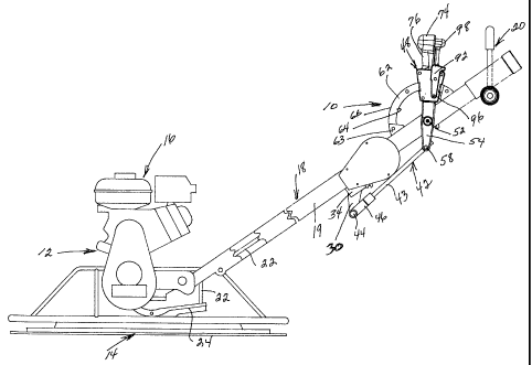
1. A quick adjustment mechanism for the blade pitch of
a rotary power trowel in which said trowel includes radial blades
pivotally supported about radial axes to vary the pitch thereof, an
operating handle extending-upwardly from the trowel in inclined
relation to enable an operator to control movement of the trowel,
a tension member extending along the operating handle and
operatively associated with said blades to pivot the blades to vary
their pitch, said quick adjustment mechanism comprising a control
lever having a central portion pivotally supported from said
operating handle, said lever including a lower end extending below
the operating handle and an upper end extending above the operating
handle to a position to enable an operator to easily access the
upper end of the control lever to exert force thereto to move said
control lever in a pivotal manner, the lower end of said control
lever being connected to said tension member through a mechanical
advantage linkage to facilitate pivoting the blades from a flat
pitch to an angled pitch by lifting the weight of the trowel, and
a locking mechanism to releasably lock said control lever in
relation to the operating handle in a position to lock said blades
at an angle pitch; wherein said locking mechanism includes a
semicircular guide mounted on said operating handle, a locking
plate mounted on said control lever and including a slot like
26
opening receiving said guide therethrough, the dimensions of said
slot like opening enabling relative movement between the control
lever and the guide when the locking plate is perpendicular to the
guide and preventing movement of the locking member and control
lever along the guide when in non-perpendicular relation of the
locking member to the guide by edge portions of the slot like
opening in the control lever engaging a peripheral edge,surface of
said guide to lock the control lever in at least one direction, and
a trigger mechanism on said control lever to position the locking
plate in perpendicular relation to the guide to enable pivotal
movement of the control lever.
2. The structure as defined in claim 1, wherein the
upper end of said control lever includes a handle, a trigger
mechanism for operating said locking mechanism with the trigger
mechanism being associated with the upper end of said control lever
to enable an operator of the trowel to manipulate the control lever
with either hand while maintaining control of the trowel with the
other hand.
3. The structure as defined in claim 1 or 2, wherein
said locking plate and control lever include spring bias means to
bias the locking plate to a locking non-perpendicular position in
relation to the guide to preclude movement of the control lever in
one direction of movement, said trigger mechanism including a
pivotal member mounted on said control lever for movement between
a position to pivot the locking plate to a release perpendicular
27
position and permit the locking plate to pivot to a locking
position.
4. A quick adjustment mechanism for the blade pitch of
a rotary power trowel in which said trowel includes radial blades
pivotally supported about radial axes to vary the pitch thereof, an
operating handle extending upwardly from the trowel in inclined
relation to enable an operator to control movement of the trowel,
a tension member extending along the operating handle and
operatively associated with said blades to pivot the blades to vary
their pitch, said quick adjustment mechanism comprising a control
lever having a central portion pivotally supported from said
operating handle, said lever including a lower end extending below
the operating handle and an upper end extending above the operating
handle to a position to enable an operator to easily access the
upper end of the control lever to exert force thereto to move said
control lever in a pivotal manner, the lower end of said control
lever being connected to said tension member, and a locking
mechanism to releasably lock said control lever in relation to the
operating handle in a position to lock said blades at an angle
pitch; wherein said locking mechanism includes a semicircular guide
mounted on said operating handle, said control lever including a
slot like opening receiving said guide therethrough, a locking
plate on said control lever including a slot like opening receiving
said guide therethrough, the dimensions of said slot like openings
enabling relative movement of the control lever along the guide
28
when the locking plate is perpendicular to the guide and preventing
movement of the control lever along the guide when the locking
plate is in non-perpendicular relation to the guide by edge
portions of the slot like opening in the locking plate engaging a
peripheral edge surface of said guide to lock the control lever
against pivotal movement in at least one direction, and a trigger
mechanism on said control lever to pivot the locking plate, into
perpendicular relation to the guide to enable pivotal movement of
the control lever.
5. The structure as defined in claim 4, wherein the
upper end of said control lever includes a trip handle, a trigger
mechanism for operating said locking mechanism with the trigger
mechanism being associated with the trip handle at the upper end of
said control lever to enable an operator of the trowel to
manipulate the control lever with either hand while maintaining
control of the trowel with the other hand.
6. The structure as defined in claim 4 or 5, wherein
said locking plate and control lever include spring bias means
therebetween to bias the locking plate to a non-perpendicular
locking position in relation to the guide to preclude movement of
the control lever in said one direction of movement, said trigger
mechanism including a pivotal member mounted on said control lever
for movement between a position to pivot the locking plate to a
released perpendicular position and to permit the spring bias means
to pivot the locking plate to a non-perpendicular locking position.
29
7. The structure as defined in any one of claims 4 to 6,
wherein said control lever is connected to said tension member
through a mechanical advantage linkage to facilitate change in the
blade pitch by exerting a reduced force on the control lever to
support the weight of the trowel when increasing and decreasing the
blade pitch.
8. The structure as defined in claim 7, wherein said
mechanical advantage linkage includes said control lever being
pivotally connected to the operating handle at a pivot point closer
to a lower end thereof, a connecting rod connected to the lower end
of the control lever, a pivot link pivotally mounted on said
operating handle, said pivot link including a lower end pivotally
connected to said connecting rod and an upper end connected to said
tension member, said pivotal mounting of said link on said
operating handle being located closer to the upper end of said
link.
9. The structure as defined in claim 4, wherein said
control lever is connected to said tension member through a
mechanical advantage linkage to facilitate change in the blade
pitch by exerting a reduced force on the control lever to support
the weight of the trowel when increasing and decreasing the blade
pitch.
10. The structure as defined in claim 9, wherein said
mechanical advantage linkage includes said control lever being
pivotally connected to the operating handle at a pivot point closer
to a lower end thereof, a connecting rod connected to the lower end
of the control lever, a pivot link pivotally mounted on said
operating handle, said pivot link including a lower end pivotally
connected to said connecting rod and an upper end connected to said
tension member, said pivotal mounting of said link on, said
operating handle being located closer to the upper end of said
link.
11. A rotary power trowel including radial blades
pivotally supported for pivotal movement about radial axes to vary
the pitch thereof, an operating handle extending upwardly from the
trowel in inclined relation to enable an operator to control
movement of the trowel, a flexible tension member extending along
the operating handle and operatively associated with said blades to
pivot the blades to vary their pitch, and a quick adjustment
mechanism varying the pitch angle of said blades, said quick
adjustment mechanism comprising a control lever having a central
portion pivotally supported on said operating handle, said lever
including a lower end extending below the operating handle and an
upper end extending above the operating handle to a position to
enable an operator to grasp the upper end of the control lever with
one hand to exert force thereon to pivotally move said control
lever, the lower end of said control lever being connected to said
tension member through a mechanical advantage linkage to facilitate
pivoting the blades from a flat pitch to an angled pitch by lifting
the weight of the trowel, and a locking mechanism to releasably
31
lock said control lever in pivotal relation to the operating handle
in a position to lock said blades at a pitch angle, said mechanical
advantage linkage including said control lever being pivotally
connected to the operating handle at a pivot point closer to a
lower end of said lever than to an upper end of said lever, a
connecting rod connected to the lower end of the control lever, a
pivot link pivotally mounted on said operating handle, said pivot
link including a lower end pivotally connected to said connecting
rod and an upper end connected to said tension member, said pivotal
mounting of said link on said operating handle being located closer
to said upper end of said link than to said lower end of said link,
said upper end of said link being arcuate and provided with a
groove receiving said flexible tension member, said flexible
tension member being anchored to one end of said groove and
tangentially engaging said groove during pivotal movement of the
link.
12. The structure as defined in claim 11, wherein the
upper end of said control lever includes a control handle, a
trigger mechanism mounted on an upper end portion of said control
lever, said trigger mechanism being mounted on said control lever
closely adjacent to and generally aligned with said control handle
to enable an operator of the trowel to manipulate the control
lever, control handle and trigger mechanism with either hand while
maintaining control of the trowel with the other hand.
32
13. The structure as defined in claim 11 or 12, wherein
said control handle extends transversely of an upper end of said
control lever, said trigger mechanism being mounted on said control
lever below said transverse control handle and aligned with a
central, portion of said transverse control handle, said locking
mechanism including a semicircular guide fixedly mounted on said
operating handle, a locking plate mounted on said control lever for
movement between perpendicular and non-perpendicular relation to
said guide, said locking plate including a slot like opening
receiving said guide therethrough, the dimensions of said slot like
opening enabling relative movement between the control lever and
the guide when the locking plate is perpendicular to the guide and
preventing movement of the control lever along the guide when said
locking plate is in non-perpendicular relation to the guide by edge
portions of the slot like opening in the locking plate engaging
opposed peripheral edge surfaces of said guide to lock the control
lever in at least one direction, said trigger mechanism on said
control lever engaging said locking plate to move said locking
plate into perpendicular relation to the guide to enable pivotal
movement of the control lever in both directions.
14. The structure as defined in claim 13, wherein said
locking plate and control lever include spring bias means to bias
the locking plate to a locking non-perpendicular position in
relation to the guide to preclude movement of the control lever in
one direction of movement, said trigger mechanism including a
33
pivotal trigger mounted on said control lever immediately below the
central portion of the control handle for manual movement against
the spring bias means to pivot the locking plate to a released
position perpendicular to said guide and permit said spring bias
means to pivot said locking plate to a locking non-perpendicular
relation to said guide when said trigger is released.
15. The structure as defined in claim 11, wherein said
locking mechanism includes a semicircular guide mounted fixedly on
said operating handle and extending through an opening in said
control lever, said guide including a plurality of teeth on an
inner peripheral edge surface, said- control lever including a
spring biased latching pin engaged with said teeth to lock the
control lever in pivotal position, said control lever including a
latch pin releasing mechanism including a control button extending
beyond an upper end of said control lever to enable an operator to
depress the button by thumb pressure when grasping the upper end of
the control lever to release the control lever from the guide to
enable the lever to be pivoted in one direction to increase the
pitch of the blades and permitting the weight of the trowel on the
blades to move the control lever in the opposite direction to
enable the blade pitch to reduce.
16. A rotary power trowel in which said trowel includes
radial blades, said blades being supported for pivotal movement
about radial axes to vary the pitch thereof, an operating handle
extending upwardly from the trowel in inclined relation to enable
34
an operator to control movement of the trowel, a flexible tension
member extending along the operating handle and operatively
associated with said blades to pivot the blades to vary their
pitch, and a quick adjustment mechanism varying the pitch angle of
said blades, said quick adjustment mechanism comprising a control
lever having a central portion pivotally supported on said
operating handle, said lever including a lower end extending below
the operating handle and an upper end extending above the operating
handle to a position to enable an operator to grasp the upper end
of the control lever with one hand to exert force thereon to
pivotally move said control lever, the lower end of said control
lever being connected with said tension member, and a locking
mechanism to releasably lock said control lever in relation to the
operating handle in a position to lock said blades at a pitch
angle, said upper end of said control lever including a T-shaped
control handle at said upper end, a trigger mechanism for operating
said locking mechanism, said trigger mechanism being mounted on
said control lever below and in alignment with a central portion of
said T-shaped handle and spaced closely below said T-shaped handle
to enable an operator of the trowel to manipulate the control lever
and trigger mechanism on the locking mechanism with either hand
while maintaining control of the trowel with the other hand.
17. The structure as defined in claim 16, wherein said
locking mechanism includes a semicircular guide mounted on said
operating handle with the center of the guide coinciding with the
pivot axis of the control lever, said control lever including a
slot opening receiving said guide therethrough, a locking plate on
said control lever including a slot opening receiving said guide
therethrough, the dimensions of said slot opening enabling relative
movement of the control lever along the guide when the locking
plate is perpendicular to the guide and preventing movement of the
control lever along the guide when the locking plate is in non-
perpendicular relation to the guide by upper and lower edges of the
slot opening in the locking plate engaging opposed peripheral edge
surfaces of said guide to lock the control lever against pivotal
movement in at least one direction, said trigger mechanism on said
control lever engaging and pivoting said locking plate into
perpendicular relation to the guide to enable pivotal movement of
the control lever in both directions.
18. The structure as defined in claim 17, wherein said
locking plate and control lever include spring bias means
therebetween to bias the locking plate to a non-perpendicular
locking position in relation to the guide to preclude movement of
the control lever in said one direction of movement, said trigger
mechanism including a pivotal member mounted on said control lever
for movement between a position to pivot the locking plate to a
released perpendicular position and to permit the spring bias means
to pivot the locking plate to a non-perpendicular locking position.
19. The structure as defined in claim 18, wherein said
control lever is connected to said tension member through a
mechanical advantage linkage to facilitate change in the blade
pitch by exerting a reduced force on the control lever to support
36
the weight of the trowel when increasing and decreasing the blade
pitch.
20. The structure as defined in claim 19, wherein said
mechanical advantage linkage including said control lever being
pivotally connected to the operating handle at a pivot point closer
to said lower end of said lever than to said upper end of said
lever, a connecting rod connected to said lower end of the control
lever, a pivot link pivotally mounted on said operating handle,
said pivot link including a lower end pivotally connected to said
connecting rod and an upper end connected to said tension member,
said pivotal mounting of said link on said operating handle being
located closer to said upper end of said link than to said lower
end of said link, said link including an arcuate upper end provided
with a groove receiving said flexible tension member, said flexible
tension member being anchored to one end of said groove and
tangentially engaging said groove during pivotal movement of the
link.
21. The structure as defined in claim 17, wherein said
control lever includes a hollow housing having said slot opening
therein receiving said guide, a spring between the locking plate
and housing to bias the locking plate into locking position in non-
perpendicular relation to the guide with edges of the slot opening
in said locking plate frictionally engaging opposed peripheral
edges of said guide to prevent pivotal movement of the upper end of
said control lever toward said trowel blades thereby preventing the
37
weight of the trowel moving the trowel blades toward a zero pitch
angle.
22. The structure as defined in claim 21, wherein said
slot opening in the locking plate includes top and bottom edges
frictionally engaged with opposed peripheral edges of said guide to
compress said spring when said upper end of said control lever is
moved away from the trowel and enabling said locking plate to pivot
to perpendicular relation to said guide for increasing the pitch
angle of the trowel blades without actuating said trigger
mechanism.
23. The structure as defined in claim 22, wherein said
trigger mechanism includes a pivotal member mounted on said control
lever and including an actuating pad facing away from said trowel,
said pivotal member having a lower end engaged with said locking
plate and moving said locking plate to unlocked perpendicular
relation to said guide to enable the upper end of said control
lever to move toward said trowel to permit said trowel blades to
pivot to decrease the pitch angle of said trowel blades.
24. The structure as defined in claim 23, wherein said
actuating pad is located below said upper end of said control
lever, generally along a center line of said control lever and
adjacent said upper end thereof to enable said actuating pad to be
engaged by the thumb of either hand of a trowel operator when
grasping said upper end of said control lever with either hand
whole controlling movement of the trowel with the other hand.
38
25. A rotary power trowel including radial blades
pivotally supported about radial axes to vary the pitch thereof, a
hollow operating handle extending upwardly from the trowel in
inclined relation, a handle bar assembly mounted at an upper end of
said operating handle to enable an operator,to control movement of
the trowel, a flexible tension member extending along the interior
of said operating handle and operatively associated with said
blades to pivot the blades to vary their pitch, and a quick
adjustment mechanism varying the pitch angle of said blades, said
quick adjustment mechanism comprising a control lever having a
central portion pivotally supported on said operating handle, said
lever including a lower end extending below the operating handle
and an upper end extending above the operating handle to a position
to enable an operator to grasp the upper end of the control lever
to exert force thereto to pivotally move said control lever with
one hand while controlling the trowel with the other hand engaging
the handlebar assembly, the lower end of said control lever being
connected to said tension member through a mechanical advantage
linkage to facilitate change in the blade pitch by exerting a
reduced force on the control lever to support the weight of the
trowel when increasing and decreasing the blade pitch, said
mechanical advantage linkage including said control lever being
pivotally connected to the operating handle at a pivot point closer
to said lower end of said control lever than to said upper end of
said control lever, a connecting rod connected to the lower end of
the control lever, a pivot link pivotally supported below said
39
operating handle, said pivot link including a lower end pivotally
connected to said connecting rod and an upper end extending into
the interior of said operating handle and connected to said
flexible tension member, said pivotal mounting of said link on said
operating handle being located closer to said upper end of said
link than to said lower end of said link, said upper end of said
pivot link including an arcuate groove having a center coincident
with the axis of pivotal movement of said link, said arcuate groove
receiving said tension member, said tension member having an end
attached to an end of said arcuate groove remote from the rotary
blades and in tangential engagement with the arcuate groove during
pivotal movement of said pivot link to move the tension member in
the interior of the hollow operating handle.