Note: Descriptions are shown in the official language in which they were submitted.
CA 02361478 2001-11-08
(F:\TT\BL\PATENTE\26503CH\26503NZ.DOC Prt: 23.10.2001 BL)
- 1 -
METHOD AND DEVICE FOR SIMULATING DETONATING PROJECTILES
Field of the Invention
The present invention refers to a method for simulating the
effect of exploding projectiles fired by weapons.
Furthermore, the invention refers to a device for carrying
out a method for simulating the effect of exploding
projectiles fired by weapons.
Background of the Invention
Known types of detonating projectiles are those fired by
ballistic weapons (mortars, artillery). For simulation
purposes, the trajectory and the location of the detonation
are calculated on the basis of the gun orientation and other
parameters. Due to the relatively long time of flight of
several seconds, this calculation can be performed by a
central computer.
Recently, however, infantry weapons have been introduced
which also operate according to this principle. These
weapons are essentially similar to rifles. The soldier takes
aim at the edge of a building, for example, thereby allowing
the targeting device to determine the corresponding distance
and store it. Then the soldier aims past the edge and fires.
The shot travels the previously determined distance and
detonates at the end thereof, or at some distance before or
behind it. Essentially, it is thereby possible to hit a
target behind the aimed edge, or, in simple terms, to shoot
to a certain extent "around the corner".
Since in particular the time of flight is for this kind of
weapon rather in the range of milliseconds, it is not
CA 02361478 2001-11-08
(F:\TT\BL\PATENTE\26503CH\26503NZ.DOC Prt: 23.10.2001 BL)
- 2 -
possible to simulate the effect of this weapon by a central
computer without admitting an unrealistic delay between the
firing and its effect.
Summary of the Invention
It is therefore an object of the present invention to
provide a method and a device for simulating the effect of
detonating projectiles which allows realistically short
delays between firing and detonation at the target location.
According to a first aspect of the invention this object is
attained by a method wherein a weapon signal emitted by the
weapon when fired is detected by a sensor located near the
target area and the sensor prompts at least one associated
transmitter to emit an impact signal which is adapted to
cover also that portion of the impact area of the simulated
explosion which cannot be covered by the weapon signal of
the weapon.
According to a second aspect of the invention there is
provided a device which comprises a sensor and a
transmitter, which sensor being effectively linked to the
transmitter in such a manner that a weapon signal which is
detected by the sensor and which indicates the simulated
firing of a projectile having an explosive effect in the
target area prompts the emission of an impact signal in the
impact area of the simulated projectile by the transmitter.
According to a third aspect of the invention there is
provided a device according to the second aspect, wherein
the sensor is directionally sensitive and preferably
comprises a plurality of sensor elements each of which
CA 02361478 2001-11-08
(F:\TT\BL\PATENTE\26503CH\26503NZ.DOC Prt: 23.10.2001 BL)
- 3 -
covers a sector of the total angular range covered by the
sensor in order to determine the angle of incidence of the
weapon signal emitted by the weapon at least stepwise and
wherein the transmitter is adapted to emit the impact signal
with a directionally variable range and particularly
comprises a plurality of transmitter elements each of which
is adapted to supply approximately a sector with a
controllable range, so that the transmitter is adapted for
being triggered by the sensor according to the angle of
incidence of the weapon signal of the weapon in such a
manner that the area supplied with an effective impact
signal by the transmitter represents an improved
approximation to the impact area of a projectile exploding
in reality.
The principal aspect of the method according to the
invention is that firing information emitted by the
simulated weapon is locally detected and emitted in the
impact area of the simulated detonation, i.e. particularly
also in the area which is invisible from the position of the
shooter. Preferably, a transceiver unit is provided on the
obstacle for this purpose. The receiver of this unit records
information emitted by the weapon that the shot has been
fired and activates the transmitter unit which emits
information on the simulated detonation in the impact area.
Participants in the exercise who are present in the impact
area and equipped with corresponding receivers are thus
informed of the fact that they have been hit and are
eliminated or considered as injured.
According to a preferred embodiment, the direction from
which the weapon is pointed at the obstacle is furthermore
determined in order to be able to demarcate the impact area
CA 02361478 2001-11-08
(F:\TT\BL\PATENTE\26503CH\26503NZ.DOC Prt: 23.10.2001 BL)
- 4 -
of the detonation more precisely. In this case it is further
preferred that the transmitter also offers the possibility
of selectively supplying the impact signal to certain
portions of the possible impact area only.
Brief Description of the Drawings
The invention will be explained in more detail with
reference to an exemplary embodiment illustrated in the
figures.
FIG. 1 schematically shows a simulation situation;
FIG. 2 shows an enlarged top view of a transceiver unit;
and
FIG. 3 shows a front view of a transceiver unit.
Description of the Preferred Embodiment
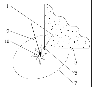
According to the invention a transceiver unit 5 is affixed
to the edge 1 of a schematically illustrated building 3. It
is noted that the size of transceiver unit 5 is shown in
FIG. 1 in an exaggerated manner compared to simulated impact
area 7 of the detonation.
The purpose of the simulation is to simulate the effect of a
projectile approaching on trajectory 9 and detonating at
location 10. It is assumed in an idealizing manner that the
impact of the explosion at location 10 covers area 7,
wherein trajectory 9 is flat. The simulation requires that
the corresponding weapon is provided with a device allowing
the emission of firing information into the area visible
from the weapon. Generally, this would be a simulation
CA 02361478 2001-11-08
(F:\TT\BL\PATENTE\26503CH\26503N2.DOC Prt: 23.10.2001 BL)
- 5 -
device using a laser source. Known embodiments of such
devices are already capable of compensating elevation and
lead by projecting the laser beam into the target area with
a lateral and/or vertical deviation. For explosive
projectiles and other applications, it is known that the
laser device sweeps a larger part of the target area, i.e.
that the laser beam is guided over a determined surface in a
zigzag movement, for example, thereby activating detectors
provided in equipment and on training participants in the
impact area.
In the case of the weapon for which the simulation is
intended, at first, edge 1 is targeted. The laser beam of
the weapon hits transceiver unit 5. If necessary, the
receiver of the unit is thereby set to an alarm condition.
The receiver is directionally sensitive in order to be able
to determine the direction of trajectory 9 at least
approximately. Furthermore, the transceiver unit comprises a
reflector device 20 which reflects the laser beam back onto
itself. This allows the targeting device to detect that its
beam has hit a transceiver unit 5. Subsequently, as the
weapon is pointed at target location 10, the targeting
device may deviate the laser beam with respect to the
orientation of the weapon or expand it in such a manner that
it still hits transceiver unit 5.
When the weapon is fired, a corresponding piece of
information is transmitted by the laser beam to the receiver
of the transceiver unit. This will activate the transmitter
section 27 of transceiver unit 5, which in turn will emit
the impact signal in impact area 7. In the example shown in
FIG. 1 it is assumed that impact area 7 represents
essentially an ellipse whose longer axis is perpendicular to
trajectory 9. Equipment and/or simulation participants
CA 02361478 2001-11-08
(F:\TT\BL\PATENTE\26503CH\26503NZ.DOC Prt: 23.10.2001 BL)
- 6 -
present in impact area 7 and carrying detectors responding
to the signal of the transmitter of transceiver unit 5 are
thus immediately after the firing informed of the fact that
they are exposed to the impact of this weapon by the
activation of their sensors.
In other words, transceiver unit 5 transforms the hit signal
emitted by the simulation device of the weapon into an
impact signal that covers impact area 7, i.e. also locations
which cannot be attained by the hit signal of the weapon
itself for physical reasons.
FIGs. 2 and 3 show transceiver unit 5 on a greatly enlarged
scale. It comprises essentially three sections. Reflector
section 20 is arranged at the top and serves for reflecting
the laser signal emitted by the weapon back onto itself,
thereby allowing the weapon to locate transceiver unit 5.
Sensor 22 is arranged in the center. It is composed of a
number of sensor elements 24, each of which surveys a
sector. For example, the arrangement of FIG. 2 allows the
determination of the horizontal (virtual) trajectory 9 with
a resolution of 45 degrees. Sensor elements 24 may be usual
photo-sensitive elements which are separated from each other
by separating walls 26 in order to ensure the sector-shaped
directional characteristic.
Transmitter 27 is arranged at the bottom of transceiver unit
5. It comprises a number of transmitter elements 29, each of
which approximately covers a respective sector of the area
surrounding the transceiver unit. Furthermore, the non-
represented control system of transceiver unit 5 also
controls the transmitting power of transmitter elements 29
in order to control the range of the impact signal emitted
CA 02361478 2001-11-08
(F:\TT\BL\PATENTE\26503CH\26503NZ.DOC Prt: 23.10.2001 BL)
_ 7 _
by the transmitter elements and thereby to reproduce the
shape of impact area 7.
The control both of the simulation device of the weapon and
of transceiver unit 5 can be realized by conventional means.
For example, each sensor may be connected to a threshold
amplifier which responds when a signal is received and
ensures that each transmitter element is supplied with a
certain amount of energy whereby the range of the impact
signal in the corresponding direction is adjusted. The
resulting shape of the reproduced impact area 7 corresponds
to the orientation of the respective sensor element 24 and
thus to that of trajectory 9.
Control devices for this purpose are known to those skilled
in the art and therefore need not be explained in more
detail.
An alternative possibility of controlling transceiver unit 5
consists in providing the respective building 3 with a
sufficiently powerful simulation computer which detects the
weapons, particularly of the simulated type, that are
monitored by the transceiver units and possibly fired only
near the house and activates the corresponding transmitter
units 20. With this arrangement, it is additionally possible
to provide further transmitter units which are not
integrated in the transceiver units, and/or to inform
participants or equipment of their location in the impact
area, e.g. by radio. Since this local computing unit may
basically also be informed of the position and the number of
all nearby participants, equipment, and weapons, it may
simulate the application of the weapons, complementarily
with the local transceiver units 5, even if they are not
used for their actual purpose, e.g. for direct fire which
CA 02361478 2001-11-08
(F:\TT\BL\PATENTE\26503CH\26503NZ.DOC Pit: 23.10.2001 BL)
_ 8 -
may not be recognized by transceiver units 5 in certain
circumstances. However, as the case may be, a certain delay
and thus a less realistic simulation of the impact may be
the result.
On the basis of the preceding description of a preferred
embodiment, it will be understood by those skilled in the
art that various modifications can be made without departing
from the scope of the invention as defined by the claims.
For example if the requirements are less stringent, it is
possible to omit the directional sensitivity of transmitter
27 as well as of sensor 22. If the range control and
particularly also the directional characteristic of
transmitter 27 are omitted, an essentially circular impact
area surrounding the transceiver unit will be the simulated.
Even if the lack of any directional characteristic of the
sensor unit might possibly be acceptable, the transceiver
unit would then be incapable of discerning whether the
special weapon is used as intended or whether it is e.g.
aimed at the obstacle directly. A correct application of the
weapon would then be assumed in every case.
Instead of light (laser), other means of data transmission
could be considered, such as e.g. ultrasonic or radio
signals, particularly of a high frequency, e.g. 2.4 GHz.
However, in general, the latter are less suitable on account
of their sensitivity to certain atmospheric conditions which
would not substantially influence the course of the
simulation otherwise.
Further possible modifications are:
- Displaceable separating walls 26 between transmitter
elements which are positioned according to the trajectory in
CA 02361478 2001-11-08
(F:\TT\BL\PATENTE\26503CH\26503NZ.DOC Prt: 23.10.2001 BL)
- 9 -
such a manner as to allow a better reproduction of the
impact area by the transmitter elements;
- The sections of a transceiver unit (reflector, sensor,
transmitter) are in the form of separate parts, so as to
allow particularly the transmitter to be positioned for
optimum signal emission and/or to be addressed by a
plurality of sensor/reflector units;
- A 3600 detection range of the transceiver unit in order to
be mounted on a vehicle or another obstacle and to be able
to simulate fire onto the obstacle from any direction and an
impact behind the obstacle;
- An additional effect unit for producing realistic effects
such as smoke, explosion noise, light flashes.