Note: Descriptions are shown in the official language in which they were submitted.
CA 02361564 2001-08-10
WO 00/47115 PCT/US00/03621
DEVICE AND METHOD FOR FACILITATING
HEMOSTASIS OF A BIOPSY TRACT
The invention relates to a wound closure device, and more particularly, the
invention relates to a device and method for facilitating hemostasis of a
biopsy tract
or other puncture wound by injection of an absorbable sponge.
Percutaneous needle biopsy of solid organs is one of the most common
interventional medical procedures. Millions of percutaneous needle biopsies
are
performed annually in the United States and throughout the world. Percutaneous
biopsy is a safe procedure which has supplanted surgical biopsy for many
indications, such as skin biopsy and liver biopsy.
Possible complications of needle biopsy include bleeding at the biopsy site.
The amount of bleeding is related to a number of factors including needle
size, tissue
sample size, patient's coagulation status, and the location of the biopsy
site.
Vascular organs such as the liver, a common biopsy target, may bleed
significantly
after needle biopsy. To minimize bleeding from a biopsy site, small-gauge
needles
are typically used. Small gauge needles, however, produce less satisfactory
biopsy
specimens but frequently are favored over larger bored needles because of
their
perceived safety. In order to minimize the chance of internal bleeding after
biopsy,
external pressure is applied and patients are often asked to lie in
uncomfortable
positions, such as the lateral decubitus position, for a number of hours,
particularly
after liver biopsy.
Sterile sponges, such as Gelfoam, are prepared in dry sterile sheets which are
used as packing material during surgery for control of bleeding. The sponge
sheets
are left in the surgical site after surgery to stop bleeding and are absorbed
by the
body in I to 6 weeks. A number of techniques have used these absorbable
sterile
sponge materials to plug a biopsy tract to minimize or prevent bleeding. The
CA 02361564 2001-08-10
WO 00/47115 PCT/US00/03621
absorbable sponge provides a mechanical blockage of the tract, encourages
clotting,
and minimizes bleeding though the biopsy tract. Despite the advantages of
using
absorbable sponge to plug a biopsy tract this technique has not achieved
widespread
use because of difficulty in preparing and delivering the sponge material into
the
biopsy tract.
One example of a biopsy wound closure device using an implantable sponge
is described in U.S. Patent No. 5,388,588. According to this patent, a
circular
sponge of an absorbable foam material is precut and inserted into a biopsy
site by an
applicator rod having the sponge positioned on the end. Once the sponge is
implanted, the sponge absorbs blood and swells to fill the tract preventing
further
bleeding at the biopsy site. However, the sponge is difficult to deliver and
expands
slowly once delivered. In addition, this delivery method can only deliver a
sponge
of a limited size which provides less local compression than desired and may
incompletely fill the target site. Further, bleeding may continue along
sections of
the biopsy tract where no sponge has been delivered.
Accordingly, it would be desirable to provide a device and method which
will permit the delivery of an absorbable sponge to a biopsy tract in a simple
and
reliable manner.
The present invention relates to a device and method for facilitating
hemostasis of a biopsy tract or other puncture wound by injecting an
absorbable
sponge. The system according to the present invention allows the sponge to be
delivered in a hydrated state through the biopsy needle or other cannula
directly into
the puncture wound.
In accordance with one aspect of the present invention, a system for injecting
a sponge into tissue includes a pledget of sponge having a proximal end with a
larger cross sectional area than a distal end, a cannula for delivering the
pledget in a
hydrated state to the tissue, and an adaptor connectable to the cannula for
hydrating
-2-
CA 02361564 2001-08-10
WO 00/47115 PCT/US00/03621
and delivering the pledget to the cannula. The adapter has a tapered lumen
with a
large diameter proximal end and a small diameter distal end. The small
diameter
distal end is connectable to the cannula.
In accordance with an additional aspect of the present invention, a method of
forming a sponge pledget for delivery to tissue includes the steps of cutting
a strip of
sponge from a sheet of sponge material and folding the strip to form a pledget
with a
first end having a first cross sectional area and a second folded end which
has a
second cross sectional area. The second cross sectional area is larger than
the first
cross sectional area.
In accordance with a further aspect of the present invention, a system for
preparing and delivering a hydrated sponge to a cannula for delivery to tissue
includes an adaptor and a template. The adaptor includes an elongated member,
a
luer connector, and a lumen having a tapered section. The elongated member has
a
first end, a second end, and a lumen extending from the first end to the
second end.
The luer connector is provided at the second end of the elongated member for
connection to a cannula. The tapered section of the lumen tapers from a first
diameter at the first end to a second diameter at the second end which is
smaller than
the first diameter such that a dry sponge pledget having a width larger than
the
second diameter is compressible when hydrated to allow passage of the pledget
into
the second diameter. The template is configured for use in cutting the sponge
to a
size to be received in the elongated member for delivery to the cannula.
In accordance with an additional aspect of the invention, an adaptor system
for delivering a hydrated sponge to a cannula for delivery to tissue includes
an
elongated adaptor and a removable vent cap. The elongated adaptor has a distal
end,
a proximal end, a lumen tapering from a larger diameter at the proximal end to
a
smaller diameter at the distal end, and a luer connection at the distal end.
The
removable vent cap is configured to engage the luer connection. The vent cap
has a
vent hole which is configured to allow fluid to pass out of the adaptor
through the
vent hole and prevent the sponge from passing through that vent hole.
In accordance with another aspect of the invention, an adaptor system for
delivering a hydrated sponge to a cannula for delivery to tissue includes an
-3-
CA 02361564 2001-08-10
WO 00/47115 PCT/US00/03621
elongated adaptor and a removable vent cap. The elongated adaptor has a distal
end,
a proximal end, a lumen tapering from a larger diameter at the proximal end to
a
smaller diameter at the distal end, and a luer connection at the distal end. A
trail
staging member is adapted to extend from the elongated adaptor to the
removable
vent cap. A rod is also provided which extends through the removable vent cap
and
into the trail staging member. The rod has a stopping member opposite of the
removable vent cap. The stopping member has an interference fit with a lumen
extending through the trail staging member, and the stopping member is
configured
to allow fluid to pass out of the adaptor through the vent cap while
preventing the
sponge from passing through that vent cap.
In accordance with another aspect of the invention, a method of delivering a
sponge into a tissue access tract includes the steps of delivering a hydrated
sponge
pledget through a cannula positioned in a tissue access tract at a velocity E
while
withdrawing the cannula from the tissue at a velocity V to deposit the sponge
pledget and seal the tissue access tract. The velocity E is greater than or
equal to the
velocity V.
In accordance with a further aspect of the invention, a system for preparing
and delivering a hydrated sponge to a cannula for delivery to tissue includes
an
adaptor which comprises an elongated member having a first end, a second end,
and
a lumen extending from the first end to the second. A fitting is provided at
the
second end for connection to a cannula whereby a tapered section of the lumen
tapers from a first diameter at the first end to a second diameter at the
second end
which is smaller than the first diameter such that a dry sponge pledget having
a
width larger than the second diameter is compressible when hydrated to allow
passage of the pledget into the second diameter. A transparent visualization
chamber is provided which is connectable to the fitting provided at the second
end
of the elongated member.
-4-
CA 02361564 2001-08-10
WO 00/47115 PCT/US00/03621
The invention will now be described in greater detail with reference to the
preferred embodiments illustrated in the accompanying drawings, in which like
elements bear like reference numerals, and wherein:
FIG. 1 is a perspective view of a punch for forming pledgets;
FIG. 2 is a side cross sectional view of an adaptor for delivery of a pledget
to
a needle;
FIG. 3 is a side cross sectional view of a syringe for connection to the
adaptor;
FIG. 4 is a side cross sectional view of an adaptor and syringe combination
with a pledget positioned within the adaptor;
FIG. 5 is a side cross sectional view of an adaptor and syringe combination
in accordance with an alternative embodiment in which the pledget has been
hydrated and moved into a small diameter end of the adaptor;
FIG. 6 is a side cross sectional view of the loaded adaptor and syringe
combination in preparation for connection to a biopsy needle;
FIG. 7 is a side cross sectional view of an alternative embodiment of an
adaptor connected to a biopsy needle and syringe;
FIG. 8 is a side cross sectional view of an alternative embodiment of an
adaptor;
FIG. 9 is a side cross sectional view of an alternative embodiment of an
adaptor with enlargements in the lumen for kneading the pledget;
FIG. 10 is a side cross sectional view of an alternative embodiment of an
adaptor with irregularities in the lumen for kneading the pledget;
FIG. 11 is a side cross sectional view of an alternative embodiment of an
adaptor for delivery of a pledget including a template attached to the
adaptor;
FIG. 12 is a bottom view of the adaptor and template of FIG. 1 l;
FIG. 13 is a top view of the template as it is used for cutting a pledget from
an absorbable sponge sheet;
FIG. 14 is a side cross sectional view of a distal end of an adaptor with a
vent
cap attached;
-S-
CA 02361564 2001-08-10
WO 00/47115 PCT/US00/03621
FIG. 15 is a side cross sectional view of the adaptor and vent cap of FIG. 14
having a pledget staged within the adaptor;
FIG. 16 is a side cross sectional view of a portion of an organ and a system
for delivering a pledget into a biopsy tract in the organ;
S FIG. 17 is a perspective view of a trail staging device for use with the
present
invention;
FIG. 18 is a side cross sectional view of an alternative embodiment of a vent
cap;
FIG. 19 is a side cross sectional view of an alternative embodiment of a vent
cap;
FIG. 20 is a side cross sectional view of an alternative embodiment of a vent
cap;
FIG. 21 is a side cross sectional view of an alternative embodiment of a vent
cap in a closed position;
FIG. 22 is a side cross sectional view of the vent cap shown FIG. 21 in an
opened position;
FIG. 23 is a side cross sectional view of an alternative embodiment of a vent
cap in a closed position;
FIG. 24 is a side cross sectional view of an alternative embodiment of a vent
cap in an opened position;
FIG. 25 is an exploded partial cross sectional perspective view of the trail
staging device with a rod extending into the trail staging device for use with
the
present invention;
FIG. 26 is a side cross sectional view of an alternative embodiment of a vent
cap with the rod extending through the vent cap; and
FIG. 27 is a partial side cross sectional view of an alternative embodiment
of a vent cap with a rod extending through the vent cap.
The system of the present invention delivers an absorbable sponge material
in a hydrated state to facilitate hemostasis of a biopsy tract or other
puncture wound
-6-
CA 02361564 2001-08-10
WO 00/47115 PCT/US00/03621
in a simple and safe manner. The apparatus for delivering a hydrated
absorbable
sponge will be described below in connection with treatment of a biopsy tract
after a
percutaneous needle biopsy. However, the invention may be used for
facilitating
hemostasis of other types of puncture wounds or tissue access tracts to
prevent
bleeding of these wounds.
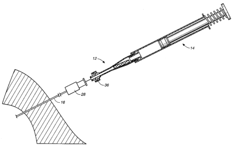
The system for facilitating hemostasis of the biopsy tract includes a punch 10
for cutting a pledget 18 of absorbable sponge material from a sheet of this
material,
an adaptor 12 for delivering the pledget to a biopsy needle 16, and a syringe
14 for
hydrating and injecting the pledget. The adaptor 12 allows a relatively large
pledget
of absorbable sponge material to be compressed and inserted into the biopsy
tract in
a hydrated state. The absorbable sponge material for use in facilitating
hemostasis
may be any absorbable sponge which is capable of deforming upon hydration to
be
delivered by fluid pressure through a biopsy needle or other cannula.
Prior to discussing the present invention in further detail, the following
terms
are defined:
"Pledget" means a piece of absorbable sponge of a generally elongated shape
having a size which allows injection in a hydrated state through a biopsy
needle or
other cannula.
"Sponge" means a biocompatible material which is capable of being
hydrated and is resiliently compressible in a hydrated state. Preferably, the
sponge
is non-immunogenic and may be absorbable or non-absorbable.
"Absorbable sponge" means sponge which when implanted within a human
or other mammalian body is absorbed by the body.
"Hydrate" means to partially or fully saturate with a fluid, such as, saline,
water, contrast agent, thrombin, therapeutic agent, or the like.
"Kneading" of the absorbable sponge material means both dry and wet
manipulation of sponge material which compresses, enlarges, or changes the
shape
of the sponge material causing the sponge material to have improved expansion
response.
FIG. 1 illustrates one example of a punch 10, also called a dye cutter, for
cutting an absorbable sponge sheet 20 into pledgets 18 of an appropriate size
for
CA 02361564 2001-08-10
WO 00/47115 PCT/US00/03621
delivery to a biopsy tract. The punch 10 includes a rectangular blade 22 fixed
to a
plate 24 having a handle 26. The punch 10 is pressed down onto a flat sheet 20
of
commercially available absorbable sponge to cut the pledget 18 of an
appropriate
size. In addition to the punch 10 illustrated in FIG. 1 other cutting devices,
such as,
a scissor type hand punch, an automatic punching machine, or a templet and
knife
may be used for preparation of the pledget 18. An alternative pledget forming
system will be discussed in further detail below with respect to FIGS. 11-13.
FIG. 2 shows the adaptor 12 according to the present invention in which the
pledget 18 is placed for hydration and for delivery through the biopsy needle
16.
The adaptor 12 allows pieces of absorbable sponge material with relatively
large
cross sections to be easily delivered through a biopsy needle 16 with a much
smaller
cross section. The adaptor 12 also functions to remove air from the pledget
18.
The adaptor 12 which delivers the hydrated pledget 18 to the needle 16
includes a first end 30 having an annular lip 32 or female luer fitting for
connection
to the syringe 14. A second end 34 of the adaptor 12 has a male luer fitting
36 for
connection to a biopsy needle 16 or other cannula. The luer fitting 36
includes a
tapered external surface 38 and a retaining ring 40 with internal threads for
receiving
an annular lip of the biopsy needle. The adaptor ~12 has an internal lumen
with a
first diameter D, at the first end 30 and a second diameter DZ at the second
end 34.
Between the first and second ends of the adaptor 12 a tapered section 42 of
the
adaptor provides a funnel for compressing the hydrated pledget 18 prior to
injection
through the biopsy needle 16 and needle hub 28.
The adaptor 12 may be formed in any known manner such as by molding
from a plastic material. Preferably, the adaptor 12 is transparent so that the
pledget
18 can be viewed through the adaptor and the user can visually monitor when
the
pledget is loaded within the adaptor and when the pledget has been delivered
into
the needle. The adaptor lumen may be provided with a friction reducing coating
for
improved delivery. The delivery fluid also reduces friction for improved
delivery by
wetting the exterior surface of the pledget 18.
The syringe 14 includes a male luer fitting 46, a fluid chamber 48, and a
plunger 50. The first end 30 of the adaptor 12 is connectable to the luer
fitting 46 of
_g_
CA 02361564 2001-08-10
WO 00/47115 PCT/US00/03621
the conventional syringe 14. The syringe 14 may be provided with a spring 52
for
automatic filling of the syringe 14 with a predetermined volume of fluid.
Alternatively, the syringe may include a threaded syringe plunger, as shown in
FIG.
7, for accurate injection of small quantities of fluid. The syringe volume
will vary
depending on the amount of fluid needed for hydration and delivery of the
pledget
18 through the biopsy needle 16.
A biopsy needle 16 for use with the present invention is preferably a co-axial
biopsy needle, such as a bi-axial or a tri-axial biopsy needle. A co-axial
biopsy
needle includes an outer needle or cannula through which a tissue sample is
removed
with a tissue scoop or other biopsy instrument. Once the tissue sample has
been
removed, the outer cannula remains in the patient as illustrated in FIG. 6.
Although
the cannula for delivery of the sponge pledget has been described as a biopsy
needle,
the cannula may be a catheter, sheath, or any other type of cannula.
A preferred method of facilitating hemostasis of a biopsy tract will be
described with reference to FIG. 4 which shows the loading and hydration of
the
pledget 18 within the adaptor 12. A pledget 18 is cut as described above and
placed
within the adaptor 12 from the first end 30 of the adaptor. The syringe 14 is
filled
with a predetermined amount of fluid, such as saline, and is connected to the
first
end 30 of the adaptor 12 by the luer fitting 46. The plunger 50 of the syringe
14 is
then depressed slowly causing fluid to pass into the adaptor 12, hydrating the
pledget 18, and filling the adaptor with a column of fluid. Care should be
taken to
inject the fluid slowly to prevent the pledget from being ejected out of the
second
end 34 of the adaptor. Preferably, the user waits a few seconds once the fluid
is
injected into the adaptor 12 until the pledget 18 is adequately hydrated
creating a
lubricous surface on the pledget. The pledget 18 may expand within the adaptor
to
fill or nearly fill the lumen of the adaptor. The adaptor 12 with the pledget
18
hydrated within the proximal end is ready to inject tr~e pledget into a biopsy
tract to
facilitate hemostasis within the biopsy tract. The adaptor 12 may be loaded
prior to
beginning the biopsy procedure.
After the biopsy procedure has been completed, the outer sheath of the
biopsy needle 16 through which the biopsy has been taken is maintained in
place
-9-
CA 02361564 2001-08-10
WO 00/47115 PCT/US00/03621
within the biopsy tract, as shown in FIG. 6. The biopsy needle 16 provides pre-
established targeting of the delivery site for delivery of the absorbable
sponge
pledget 18 and eliminates the uncertainty of re-access. The luer fitting 36 of
the
adaptor 12 is connected to the biopsy needle hub 28, as illustrated in FIG. 6.
The
biopsy needle 16 is withdrawn a short distance, such as about 1 to 20 mm,
along the
biopsy tract to provide space for the pledget 18 to be received in the biopsy
tract.
Additional fluid is then rapidly injected by the syringe to move the pledget
18 into
the biopsy needle 16. When the adaptor lumen has been blocked by the hydrated
pledget 18 which has swelled within the adaptor, injection of additional fluid
will
push the pledget through the tapered section 42 of the adaptor. If the adaptor
lumen
has not been entirely blocked by the pledget 18, the venturi effect will help
draw the
pledget through the tapered section 42 of the adaptor. After the pledget 18 is
moved
to the biopsy needle 16, the pledget 18 is then delivered from the needle 16
to the
biopsy tract by rapid injection of additional fluid by the syringe 14. The
hydrated
pledget 18 quickly expands upon delivery to fill the available space in the
biopsy
tract to facilitate hemostasis and provide localized compression.
As illustrated in the cross sectional view of FIG. 7, one example of a needle
hub 28 has an interior diameter D3 which is larger than the diameter DZ at the
distal
end 36 of the adaptor 12. The large internal diameter needle hub 28 allows the
hydrated pledget 18 which has been compressed by the tapered section 42 of the
adaptor to expand in the needle hub before being compressed again into the
needle
lumen. This compression and enlargement of the hydrated absorbable sponge
material, does not adversely effect the pledget delivery and in fact improves
the
expansion response of some delivered sponge materials as will be discussed in
further detail below.
A smooth tapered transition between the lumen of the needle hub 28 and the
needle lumen helps to provide for easy injection of the pledget 18. However,
needles having internal steps between the needle hub 28 and the needle 16 have
been
used and the pledget 18 is still injected successfully. According to an
alternative
embodiment of the invention, the needle hub 28 may be designed to have a inner
-10-
CA 02361564 2001-08-10
WO 00/47115 PCT/US00/03621
diameter approximately the same as the inner diameter DZ at the distal end 36
of the
adaptor.
Preferably, specific measured doses of fluid are used to achieve each of the
steps of the treatment procedure depending on the pledget size and the
dimensions of
the adaptor 12, the needle 16, and the needle hub 28. The pledget 18 should be
completely delivered into the biopsy tract by the fluid and only a minimal
amount of
extraneous fluid should be delivered. For example, the pledget 18, once inside
the
needle, may be delivered with about 0.02 to 1.5 ml of fluid depending on the
size of
the needle 16 used. Injection of larger amounts of fluid may distend the
biopsy tract
or displace the pledget within the organ.
According to one example, a pledget 18 having a size of approximately 20
mm by 2 mm cut from a sheet of commercially available Gelfoam having a
thickness of approximately 1.5 mm can be hydrated and injected through a
standard
18 gauge, approximately 15 cm long biopsy needle with approximately 0.9 ml of
fluid. An adaptor according to this example has a first diameter D, of about
0.38
cm, a second diameter Dz of about 0.14 cm, a total length of about 3.80 cm,
and a
taper angle of about 45°. About 0.3 ml of fluid is injected slowly to
hydrate the
pledget 18 and fill the adaptor with a column of fluid. Approximately 0.3 ml
of
fluid is then injected to load the pledget 18 from the adaptor 12 into the
biopsy
needle 16. Finally, about 0.3 ml of fluid is injected to deliver the pledget
18 into the
biopsy tract. Loading of the pledget from the adaptor 12 into the needle 16
and
delivery from the needle to the biopsy tract can be combined in one step by
delivery
of approximately 0.6 ml. Accurate and complete injection of the pledget with a
minimum amount of extraneous fluid is achieved by this volumetric injection
technique.
According to an alternative embodiment of the adaptor illustrated in FIG. 5,
vent holes 44 extend through the side walls of the adaptor 12 adjacent the
second
end 34 for venting fluid during loading of the pledget 18. As illustrated in
FIG. 5,
the user places a forger over the second end 34 of the adaptor 12 to prevent
the
pledget from exiting the adaptor. The plunger 50 of the syringe 14 is then
depressed
slowly causing fluid to pass into the adaptor 12 and hydrate the pledget.
Preferably,
-11-
CA 02361564 2001-08-10
WO 00/47115 PCT/US00/03621
the user waits a few seconds once the fluid is injected into the adaptor 12
until the
pledget 18 is hydrated. Once the pledget 18 is hydrated, additional fluid is
then
injected quickly into the adaptor 12 to move the pledget 18 from the first end
30 of
the adaptor towards the second end 34 of the adaptor. As the pledget 18 is
compressed by the tapered section 42 of the adaptor 12 air and fluid are
allowed to
escape from the adaptor through the vent holes 44. Once the pledget 18 has
been
moved into the position illustrated in FIG. 5 adjacent the second end 34,
fluid
injection is halted. The adaptor 12 with the hydrated pledget 18 within the
distal end
is ready to insert the pledget through a biopsy needle to facilitate
hemostasis within
the biopsy tract.
As an alternative to placement of a finger at the distal end of the adaptor 12
during advancement of the pledget 18 through the tapered section 42, a
removable
cap may be used. Further, the vent holes 44 may be omitted and a screen or a
cap
having a screen may be used to allow fluid to pass through the screen while
the
screen prevents the pledget 18 from being ejected. One example of a vent cap
will
be described in further detail below with respect to FIGS. 14 and 15.
An alternative embodiment of the delivery system is illustrated in FIG. 7 in
which an adaptor 12 is provided with a pressure indicator 64 to monitor
pledget
injection. Preferably, the pressure indicator 64 is removably attached at a
luer fitting
66 provided or. a side of the adaptor 12. The pressure indicator 64 includes a
pressure dome 68 movable from the convex shaped extended position illustrated
in
FIG. 7 to a flat position depending on the pressure inside the adaptor 12.
Internal
pressure within the biopsy needle 16, the adaptor 12, and the syringe 14 will
drop as
the pledget 18 is extruded from the biopsy needle into the biopsy tract. This
causes
the pressure dome 68 to move from the convex position illustrated in FIG. 7 to
a flat
position, indicating that pledget delivery is complete.
FIG. 8 illustrates an alternative embodiment of an adaptor 12a in which the
tapered section 42a is shorter and more abrupt. The particular size and shape
of the
adaptor 12a according to either FIG. 2 or FIG. 8 may vary depending on the
size of
biopsy needle, the tissue sample size, and the size of pledget to be
delivered. One
example of the adaptor 12a of FIG. 8 for delivery of an absorbable sponge
pledget
-12-
CA 02361564 2001-08-10
WO 00/47115 PCT/US00/03621
18 through an approximately 18 gauge biopsy needle has a first adaptor
diameter D,
of about 0.25 cm or greater, preferably about 0.30 to 0.80 cm and a second
adaptor
diameter DZ of about 0.25 cm or less, preferably, about 0.05 to 0.23 cm. An
angle
made by a wall of the tapered section 42a with a longitudinal axis of the
adaptor 12a
may vary from about 5 ° to 90°, but is preferably between about
30° and 60°. The
tapered section 42a is illustrated with a substantially planar interior
surface, when
shown in cross section. However, the tapered section 42a may also have a
convex or
concave surface in cross section. The dimensions described for the adaptor 12a
are
appropriate for use with an approximately 18 gauge biopsy needle commonly used
for liver biopsies. For some of the much larger biopsy needles or cannulas
used for
skin or breast biopsies the adaptor dimensions would be scaled up accordingly.
FIG. 8 also shows a connector 70 for connecting the adaptor 12 to a syringe
14 when the proximal end of the adaptor is larger in diameter than the
standard
syringe fitting. The connector 70 includes a first end 72 for connection to
the
syringe 14 and a second end 74 for connection to the adaptor 12.
One type of absorbable sponge material which is acceptable for use in the
present invention is Gelfoam, manufactured by the Upjohn Company. Gelfoam is a
porous, pliable, cross-linked gelatin material and is available commercially
in sheet
form as pre-compressed or non-compressed sponge. The material may be provided
preformed as a pledget 18 or may be cut with a punch 10, or a stencil or
template
and knife to form a pledget as described above. Once hydrated, the pledget 18
can
be easily compressed to fit into a lumen having a smaller cross sectional area
than
the original cross sectional area of the pledget. Additionally, the kneading
of the
hydrated pledget 18 during delivery encourages air trapped within the Gelfoam
to be
expelled and replaced with fluid, allowing rapid expansion upon delivery. When
a
pledget 18 of a pre-compressed Gelfoam is hydrated and kneaded (expelling air)
during delivery, the pledget will have the absorbtion capacity to rapidly
expand to
many times (e.g., 3 or more times) its original dry volume upon delivery. When
a
pledget 18 of the non-compressed Gelfoam is hydrated and kneaded (expelling
air)
during delivery, the pledget will have the absorbtion capacity to rapidly
expand to its
-13-
CA 02361564 2001-08-10
WO 00/47115 PCT/US00/03621
original dry volume upon delivery. These properties make the Gelfoam sponge
material particularly useful for facilitating hemostasis of biopsy sites.
Abrupt lumen diameter changes within or between the adaptor 12 or the
needle 16 will improve "kneading" of the absorbable sponge material improving
S hydration of the absorbable sponge material thereby improving the expansion
properties of the hydrated delivered absorbable sponge. According to the
alternative embodiments of the adaptor illustrated in FIGS. 9 and 10,
enlarged,
recessed, or irregular areas in the lumen of the adaptor are provided to
impart
additional kneading action to the absorbable sponge material further improving
expansion properties of the sponge.
The adaptor 12b of FIG. 9 includes two enlarged areas 72 of the lumen. As
the absorbable sponge pledget 18 passes through the lumen of the adaptor 12b
the
material expands and is compressed by the adaptor to increase kneading of the
pledget. FIG. 10 illustrates another alternative embodiment of the adaptor 12c
including a lumen with a plurality of staggered irregularities 74 for improved
kneading of the absorbable sponge pledget 18. The irregularities 74 will
preferably
have a relatively smooth surface to prevent the absorbable sponge material
from
becoming caught on the irregularities.
FIG. 11 illustrates an alternative embodiment of an adaptor 112 with a
pledget formation template 122 attached to the adaptor. As shown in FIG. 11,
the
adaptor 112 includes a proximal end 130 having a female luer 132 and a distal
end
134 having a male luer 136. The pledget 118 is inserted in the proximal end
130. A
tapered section 142 is provided within the adaptor 112 for compressing the
pledget
118 into the biopsy needle.
When delivering a pledget 118 of absorbable sponge material, it is important
to deliver a desired amount of the sponge material using a minimum amount of
fluid. Some devices and methods which allow the delivery of sponge material
with
a minimum amount of fluid include the use of the pledget configuration
illustrated in
FIG. 11, the use of a vent cap for staging of the pledget as illustrated in
FIGS. 14
and 15, and the withdrawal of the biopsy needle during delivery as illustrated
in
FIG. 16.
-14-
CA 02361564 2001-08-10
WO 00/47115 PCT/US00/03621
Pledgets 118 having increased proximal cross sectional areas are more easily
delivered than pledgets with constant cross sectional areas or decreased
proximal
cross sectional areas. FIG. 11 illustrates a pledget 118 having a proximal
cross
sectional area which is approximately twice its distal cross sectional area.
The
S smaller material mass at the distal end of the pledget 188 increases the
ease of
inserting the pledget into the adaptor 112. The smaller distal end of the
pledget also
passes through the delivery cannula or biopsy needle without creating a large
back
pressure to resist the delivery of the pledget through the cannula. The larger
proximal section of the pledget 118 provides a better seal within the interior
of the
adaptor 112 and the cannula 16 which allows a minimum amount of fluid to be
used
to advance the pledget. The increased material at the proximal end of the
pledget
118 also increases the amount of sponge material delivered to the biopsy
tract.
Pledgets 118 with increased cross sectional area proximal ends may be
prepared in a variety of manners. For example, if a pledget 118 is prepared
from a
sheet of sponge material, the increased proximal mass can be achieved by
cutting the
pledget with an enlarged proximal end. Alternatively, the pledget 118 may be
formed by folding, rolling, compressing, or otherwise manipulating the sponge
material to the desired shape. The proximal pledget mass may also be increased
by
adding separate pieces of material to the proximal end of the pledget. This
additional material may be layered, wrapped, coiled or attached to the pledget
in any
other manner. The pledgets may also be formed by molding, bump extruding,
dipping, or the like. The larger cross sectional area proximal end is
generally about
1.2 to 4 times the cross sectional area of the distal end. In addition, the
proximal end
with the larger cross section area preferably extends along about 1 /8 to 3/4
of the
total pledget length.
The pledget 118 illustrated in FIG. 11 has been formed by cutting a strip of
material from an absorbable sponge sheet 20 with the aid of the template 122
as
illustrated in FIG. 13. After the strip is cut, the proximal end of the strip
is then
folded back onto itself to form a pledget 118 with an increased cross
sectional area
and material mass at a proximal end. One example of a preferred embodiment of
a
Gelfoam pledget for delivery down a 20 gauge biopsy needle or cannula has a
size
-15-
CA 02361564 2001-08-10
WO 00/47115 PCT/US00/03621
of approximately 0.1 x 1.5 x 0.06 inches and is folded as illustrated in FIG.
11 to an
overall length of about 0.9 inches. Placing this pledget 118 in an adaptor 112
having
a largest internal diameter of 0.125 inches allows the pledget to be delivered
to a 20
gauge or larger biopsy needle. Other common biopsy procedures use an 18 gauge
or
larger biopsy needle through a slightly larger guide cannula and would receive
a
somewhat larger pledget. After taking a core sample and removing the biopsy
needle from the cannula guide, a pledget 118 maybe delivered through the
cannula
to the biopsy site. The pledget 118 for use in the system employing an 18
gauge or
larger biopsy needle may be formed from a strip which is approximately 0.11 -
0.12
inches wide by about 3.125 inches long with a thickness of about 0.06 inches
and
folded to an overall length of about 2.2 inches. This pledget having a single
thickness distal end and double thickness proximal end can be delivered from
an
adaptor having a largest internal diameter of approximately 0.125 inches.
One method for forming the pledget 118 with the enlarged proximal end with
the aid of a template 122 is illustrated in FIG. 13. The template 122 is a
flat plate
having recesses 124 along one or more edges of the template. The recesses 124
have
a width and a length which corresponds to a preferred width and length of the
pledget. The recesses 124 form a raised bar 126 at a location where the
pledget
should be folded. When the template is pressed onto a sheet 20 of absorbable
sponge material, the bar 126 makes an indentation or groove in the sponge
material.
A user cuts along the side 128 and end 129 edges of the template 122 with a
blade to
form a strip of the sponge material which is then folded along the groove or
crease
formed by the bar 126 to form the pledget 118. It is important to securely
hold the
sponge sheet by applying downward pressure to the template 122 during cutting
to
prevent tearing and breaking of the sponge material. Prior to folding the
strip of
sponge material to form the pledget, the strip may be compressed with a flat
surface
of the template to compact the sponge and assist in loading the pledget into
the
adaptor 112.
Although the template 122 has been illustrated as a plate which is attached to
the adaptor 112, it should be understood that the template can also be a
separate
member. In addition, the template 122 may provide guides for forming pledgets
of
-16-
CA 02361564 2001-08-10
WO 00/47115 PCT/US00/03621
different sizes for delivery through different sized biopsy needles. The
template 122
may be provided with or without the creasing bar 126 and may be transparent or
opaque. In the opaque version, the edges of the recesses 124 are used to align
the
template with an edge of the sponge sheet 20. In contrast, in a transparent
version of
the template, the recesses 124 may be eliminated and a visual indication or
line may
be provided which assists in aligning an edge of the sponge sheet with the
template.
FIGS. 14 and 15 illustrate a preferred vent cap 70 for use with the adapter
112. As discussed above with respect to FIG. 5, vents maybe used to assist in
hydrating and staging the pledget within the adapter. In particular, vents
will allow
the pledget to be moved to a preferred axial location within the adapter 112
prior to
delivery. In addition, the vents allow fluid to be injected and air to be
removed from
the pledget prior to delivery. The vent cap 70 as illustrated in FIG. 14
includes a
female luer connector 72 including a flange 74 which is received on the male
luer
136 of the adapter 112. The vent cap 70 also includes a conical portion 76
which is
configured to extend into a distal end 134 of the adaptor 112. The conical
portion
76 has one or more fluid paths or vent holes 78 which allow air and fluid to
exit
through the vent cap but prevent the absorbable sponge material of the pledget
118
from passing through the vent cap. The vent hole may alternatively be
positioned
between the vent cap 70 and the adapter 112. Preferably, an exterior of the
conical
portion 76 forms a seal with the lumen of the adaptor 112 at the distal end.
The
diameter of the vent hole 78 is approximately 0.005 - 0.02 inches, preferably
approximately 0.01 inches. This small vent hole 78 allows the purging and
venting
of fluid and air from the adapter 112 but does not allow the pledget 118 to
pass
through the vent hole, even at high pressures such as 5 psi or greater. The
use of the
vent cap 70 allows the user to apply high pressures with the syringe used to
hydrate
the pledget. The high pressures drive the fluid into the pledget causing rapid
and
thorough hydration of the sponge material. Repeated pulsing of the fluid with
the
syringe will provide more complete hydration of the pledget.
The vent cap 70 also positions the pledget 118 at a preferred axial position
just proximal to the distal end 134 of the adapter 112 as illustrated in FIG.
15. This
positioning of the pledget 118 away from the end of the adaptor prevents the
pledget
-17-
CA 02361564 2001-08-10
WO 00/47115 PCT/US00/03621
from becoming trapped between the adaptor 112 and the biopsy needle hub 28
which is attached to the distal end of the adaptor. In addition, after
hydration of the
pledget and removal of the vent cap 70 the sponge material may tend to swell
out of
the distal end of the adapter 112. Accordingly, the conical portion 76 of the
vent cap
70 preferably extends into the adaptor 112 approximately 0.01 to 0.1 inches,
more
preferably about 0.01 to 0.03 inches.
According to the present invention, the portion of the vent cap 70 which
extends into the lumen of the adaptor 112 can be any desired shape such as
dome-
shaped, cylindrical, conical or other shape.
As described above, the pledget maybe delivered to the biopsy tract by
holding the biopsy needle or cannula 16 stationary and injecting the pledget
through
the biopsy needle. If additional pledgets are to be delivered, the biopsy
needle 16 is
withdrawn a distance sufficient to accommodate an additional pledget and the
additional pledget is then injected.
According to an alternative embodiment of the invention, the method of
delivering the pledget into the biopsy tract may include withdrawing the
biopsy
needle or cannula 16 during delivery of the pledget 18 to deliver the pledget
in an
elongated trail which follows the biopsy tract. Placing the absorbable sponge
material in a trail which fills the entire biopsy tract provides the added
benefit of
providing hemostasis along the entire biopsy tract. This is particularly
helpful for
stopping the bleeding of biopsy tracts in organs which tend to have excessive
bleeding such as the liver, kidney, spleen, and other vascular organs.
In order to achieve a trail of absorbable sponge material in the biopsy tract,
one method of the present invention involves the delivery of the pledget into
the
biopsy needle by a predetermined amount of fluid. The biopsy needle is then
withdrawn at a velocity V while the pledget material is ejected from the
biopsy
needle at a velocity E with respect to the biopsy needle. The velocity V at
which the
biopsy needle is withdrawn is equal to or less than the velocity E at which
the
absorbable sponge material is delivered. The control of injection of fluid and
withdrawal of the needle to achieve the desired trail of absorbable sponge
material in
the biopsy tract maybe controlled with an injection controlling device.
-18-
CA 02361564 2001-08-10
W'O 00/47115 PCT/US00/03621
According to an alternative embodiment of the invention illustrated in FIG.
16, the adaptor maybe used to deliver the pledget into the biopsy needle 16
and then
the adaptor is removed from the biopsy needle. A plunger or stylet 80 which is
generally provided with the biopsy needle 16 for inserting the biopsy needle
is then
used to deliver the pledget from the biopsy needle. As shown in FIG. 16, the
biopsy
needle extends through the tissue 84 and into the organ 86 for removal of a
core of
tissue. After biopsy, the pledget is injected into the needle 16 and the
plunger 80 is
placed within the biopsy needle so that a distal end of the plunger abuts the
proximal
end of the pledget 118. The plunger 80 is then held stationary while the
biopsy
needle 16 is withdrawn from the biopsy site. The plunger 80 causes the pledget
118
to be delivered in a trail 88 which fills the biopsy tract. The trail 88
preferably
extends along the entire biopsy tract to or past a surface of the organ 86.
The
delivery of the trail 88 of absorbable sponge material provides an advantage
over the
delivery of discrete blobs of material because the trail is able to provide
hemostasis
along the entire tract. In contrast, if a blob of absorbable sponge material
is
delivered within the tract at a depth of 1-2 cm from the surface of the
organs, this 1-
2 cm of biopsy tract may continue to bleed significantly.
As an alternative to delivery of the pledget as a trail, the pledget may be
delivered as a plug. To deliver a plug the plunger 80 is advanced into the
needle 16
pushing the pledget out of the distal end of the needle while the needle is
held
stationary. A combination of delivery of plugs and trails may also be used.
The
pledget material may be delivered entirely within a single anatomical
structure or
may cross two or more anatomical structures such as an organ, surrounding
tissue
and facial layer.
Although the invention is primarily intended for delivery of absorbable
sponge, non-absorbable sponge may also be delivered with the devices, systems,
and
methods of the present invention. A non-absorbable sponge may be desirable
where
it will be necessary to locate the biopsy site or tract after the procedure.
Although the pledget 18 has been shown and described as having a
rectangular cross section, pledgets of other shapes may also be used. For
example,
the pledget may be preformed in any shape, such as with a rectangular or
circular
-19-
CA 02361564 2001-08-10
WO 00/47115 PCT/US00/03621
cross section or may be rolled from a thin sheet of absorbable sponge
material. The
pledget 18 may have a mufti-sided cross section, a star shaped cross section,
or a
folded cross section and may have through or blind holes formed in the dry
pledget.
In addition, the pledget size and shape can be matched to the size and shape
of a
particular delivery site. Pledget shapes having greater surface area provided
by
features such as fins provide faster hydration.
The continuous structure of the absorbable sponge pledget 18 provides more
secure and reliable placement than a paste or liquid and can even facilitate
partial
withdrawal, removal, or movement of the delivered pledget. However, in some
cases the pledget may sheer, tear, or otherwise break apart when it is
delivered
through some small needles leaving the delivered pledget in pieces in the
biopsy
tract. The trail staging chamber 150 as shown in FIG. 17 allows the user to
visualize
the elongated pledget prior to delivery of the pledget into the biopsy needle
or other
cannula.
The trail staging chamber 150 includes an elongated transparent tube 152
having a proximal fitting 154 for connection to the adaptor 12 and a distal
fitting
158 for connection to the biopsy needle 16 or cannula. A vent cap 156 may also
be
provided which is connectable to the distal fitting 158. A vent cap 156
increases the
ability to maintain the continuity of the pledget during the delivery of the
pledget
from the adaptor 12 to the trail staging chamber 150.
In use, the pledget is delivered from the adaptor 12 into the trail staging
chamber 150 by injection of fluid until a distal end of the pledget contacts
the vent
cap 156. The elongated pledget is visualized within the staging chamber 150 to
determine whether continuity of the pledget has been maintained. If gaps or
spaces
are viewed, the pledget is discarded by removing the vent cap 156 and
expelling the
pledget. A new pledget is then injected into the staging chamber 150. Once a
continuous pledget has been observed in the staging chamber 150, the staging
vent
cap 156 is removed, the staging chamber is connected to the biopsy cannula,
and the
pledget is delivered to the biopsy tract as described above. The vent cap 156
may
have a variety of configurations such as those described above for use with
the
adaptor. Alternatively, a vent hole may be used in place of the vent cap.
-20-
CA 02361564 2001-08-10
WO 00/47115 PCT/US00/03621
Pledget discontinuities are often the result of uncontrolled advancement of
the pledget, which causes a portion of the pledget to tear away or separate
from the
pledet proximal to it. The vent cap 156 helps to maintain the continuity of
the
pledget during delivery of the pledget from the adaptor 12 to the trail
staging
chamber 150. In one embodiment, the vent cap 156 is provided with a vent of
sufficient size to create back pressure or resistance as the pledget is
delivered from
the adaptor to the trail staging chamber 150. As the pledget is delivered to
the trail
staging chamber 150, the pledget displaces media which is in front of it. The
displaced media escapes through the vent. The resistance provided by the vent
acts
as a damper to the beneficially limit or control an undesirable, sudden
advancement
of a portion of the pledget from the adaptor 12 to the trail staging chamber
150.
Therefore, discontinuities of the pledget are minimized or eliminated.
It will also be apparent to one skilled in the art that by using a non-
compressible fluid or viscous fluid as the media that it will provide
additional
1 S dampening benefits to the pledget as it is delivered from the adaptor 12
to the trail
staging chamber 150.
As shown in FIGS. 18-24, alternative embodiments of the vent cap are
disclosed. The vent caps include a valve member which has an opened and a
closed
position. In the closed position, the valve members are designed to provide a
back
pressure or resistance in the trail staging chamber 150 to the pledget as it
is delivered
from the adaptor 12. When a certain force is applied against a valve member,
the
valve member moves from the closed position to the opened position, wherein a
gas
and/or a fluid may pass through the vent cap.
For example, in FIG. 18, an alternative embodiment of the vent cap is shown
wherein the vent cap 256 has a vent hole 255 and a spring 257 which biases a
ball
valve 258. The vent hole 255 extends through the vent cap 256 and includes a
sequence of openings. The sequence of openings include a proximal opening
255a,
a distal opening 255b, and an intermediate opening 255c which is located
between
the proximal and distal openings. As shown, the ball valve 258 is in a closed
position, whereby the spring 257 biases the ball valve to occlude the distal
opening
255b.
-21-
CA 02361564 2001-08-10
WO 00/47115 PCT/US00/03621
In operation, a hydrated pledget 118 is advanced from the adaptor 12 to the
trail staging chamber 150 so that the pledget displaces the gas and/or fluid
(i.e.,
media) which is in front of the pledget. This displacement of media purges the
trail
staging chamber 150. When the media exerts sufficient force against the ball
valve
258, the ball valve moves from the closed position to an opened position so
that the
media can pass through the distal opening 255b. Accordingly, the spring biased
ball
valve 258 acts as a one-way valve which allows a gas or a fluid to pass
through the
vent hole 255.
- In another embodiment of the vent cap, as shown in FIG. 19, the vent cap
356 includes a vent hole 355 and a flapper valve 358 which is in a closed
position.
The vent hole 355 extends through the vent cap 356 and includes a proximal
opening 355a and a distal opening 355b. As in the embodiment of FIG. 18, when
the pledget displaces the media, the media will exert a force against the
flapper valve
358. When the media exerts sufficient force against the flapper valve 358, the
flapper valve moves from the closed position to an opened position so that the
media
can pass through the distal opening 355b. Accordingly, the flapper valve 358
acts as
a one-way valve which allows a gas or a fluid to pass through the vent hole
355.
As shown in FIG. 20, in yet another embodiment of the vent cap, the vent
cap 456 is substantially similar to the embodiment of FIG. 19, except that a
finger
457 can be used to act as a valve member. When the finger 457 is closed over
the
vent hole 455, the finger provides a back pressure or resistance in the trail
staging
chamber 150 to the pledget as it is delivered from the adaptor 12.
FIGS. 21 and 22 illustrate an alternative embodiment of the vent cap 556
which includes a vent hole 555, a threaded portion 557, and at least one drain
hole
558. A needle valve 559 has a needle extending member 560 and a threaded
portion
561 which threadedly engages the threaded portion 557 of the vent cap 556. The
vent hole 555 includes a proximal opening 555a and a distal opening 555b. As
shown in FIG. 21, when the needle valve 559 is in a closed position, the
needle
extending member 560 extends through the distal opening 555b, thereby
occluding
that opening and blocking the drain holes 558. By rotating the needle valve
559, the
user may change the position of the needle valve. In particular, the needle
valve can
-22-
CA 02361564 2001-08-10
VVO 00/47115 PCT/US00/03621
be moved in the direction of arrow A from the closed position of FIG. 21 to
the
opened position, as shown in FIG. 22. In the opened position, the needle
extending
member 560 does not occlude the distal opening SSSb, so that a gas and/or a
fluid
can pass through the distal opening and through the drain holes 558 to exit
the vent
cap 556.
In yet a further embodiment of the vent cap, as shown in FIGS. 23 and 24,
the vent cap 656 includes a vent hole 655 which extends through the vent cap.
The
vent hole 655 includes a proximal opening 655a and a distal opening 655b. A
stop
cock valve 657 has a passage 658 and is connected to a handle 659. The stop
cock
valve 657 is rotatably mounted in the vent cap 656 at a position located
between the
proximal and distal openings 655a, 655b. As shown in FIG. 23, the stop cock
valve
657 is in a closed position, wherein the stop cock valve is positioned so that
the
passage 658 is obstructed. As shown in FIG. 24, the stop cock valve 657 is
slidable
along the surface of the vent hole 655, and the handle 659 can pivotally
rotate the
stop cock valve in a direction of arrow B from the closed position of FIG. 23
to an
opened position. When the stop cock valve 657 is in the opened position, a gas
and/or a fluid can pass through the distal opening 655b and through the
passage 658
to exit the vent cap 656. Further, the stop cock valve 657 forms a seal with
the vent
cap 656, thereby preventing leakage of gasses or fluids from the adaptor 12
while
the stop cock valve is in the closed position.
Many types of manual, self actuated, or adjustable valves are readily
apparent to one skilled in the art. The valve member may alternatively
comprise any
suitable means including, but not limited to, a Touhy-borst valve or other
means for
controlling or regulating the flow of a gas or fluid from the adaptor 12 to
the trail
staging chamber 150. It is readily appreciated that any of these embodiments
can
interface with or be incorporated into the distal end of the trail staging
chamber.
In an alternative embodiment, as shown in FIGS. 25 and 26, a mechanical
interface 758, such as a rod, may act as a damper to beneficially limit or
control an
undesirable sudden advancement of a portion of the pledget. The rod 758
extends
through a vent hole 755 of a vent cap 756 and is slidably movable with respect
to the
vent cap 756. Further, the rod 758 is designed such that it fits in sliding
relation
-23-
CA 02361564 2001-08-10
WO 00/47115 PCT/US00/03621
with the elongated transparent tube 752 of the trail staging chamber 750. The
vent
cap 756 can couple with the distal end 760 of the trail staging chamber 750.
The rod
758 extends to occupy at least a portion, and preferably an entire length, of
the
lumen 762 of the elongated transparent tube 752. The rod 758 may further
include a
stopping member 764 to position the pledget to a desired distal location
within the
trail staging chamber 750. It is understood that the stopping member 764 fits
in
sliding relation with the lumen 762 of the elongated transparent tube 752. The
stopping member 764 may have a roughened surface to facilitate gripping
between
the stopping member and the lumen 762 of the elongated transparent tube 752.
The
roughened surface enhances the friction between the surfaces and may comprise
any
suitable means including, but not limited to, grooves, ridges, or ribs.
In an alternative embodiment, the rod 758' has a interference fit with the
vent
cap 756' such that a predetermined axial force is required from the media to
move
the rod with respect to the vent cap. The interference fit could be adjustable
by
providing an adjustable compression ring on the vent cap 756' or an adjustable
set
screw within the cap.
In another embodiment, the stopping means 764" is provided with an
interference fit with the lumen 762" of the elongated transparent tube 752".
In this
configuration, a predetermined axial force, such as a force applied from the
media, is
required to move the stopping means 764" and the rod 758" with respect to the
elongated transparent tube 752". In this embodiment, it is possible to omit
the vent
cap 756".
In still another embodiment shown in FIG. 27, an external axial force is
applied to the rod 858 such as by a spring 860. The spring 860 couples the
vent cap
856 to one end of the rod 858. Or in another alternative embodiment, a dashpot
mechanism may be used in place of the spring 860.
It should be understood by those skilled in the art that any means of applying
external force to the rod will provide the resistance or dampening to the
pledged as it
is delivered from the adaptor 12 to the trail staging chamber 150. For
example, the
operator's fingers providing external force to the rod, if applied properly,
can create
the desired back pressure or resistance sought in the above disclosed
embodiment.
-24-
CA 02361564 2001-08-10
WO 00/47115 PCT/US00/03621
The ability to deliver a continuous trail of the pledget material to a biopsy
tract is particularly important in some types of biopsies and is less
important in
others. For example, when performing a biopsy of the lung a pneumothorax or
hemothorax may occur when the delivery of the pledget material is
discontinuous.
A pneumothorax occurs when air or gas accumulates in the pleural space and a
hemothorax occurs when blood accumulates in the pleural space.
The internal diameter of the transparent tube 152 is smaller than the largest
internal diameter D, of the adaptor and is preferably between the smallest
internal
diameter DZ of the adaptor and the internal diameter of the needle or cannula.
The
length of the transparent tube 150 may vary depending on the length of the
trail of
pledget material which is to be delivered.
While the preferred embodiment of the trial staging chamber 150 is
transparent or translucent, it should be appreciated that when the internal
diameter of
the staging chamber is between DZ of the adaptor and the internal diameter of
the
needle, the odds of a continuous trail are improved by use of the trail
staging
chamber 150 with or without the added benefit of visualization. Thus, an
opaque
trial staging chamber 150 may also be used.
In some instances it may be desirable to deliver multiple pledgets in spaced
apart positions along the biopsy tract, particularly for a long biopsy tract.
For
delivery of additional pledgets, the biopsy needle 16 is retracted a distance
sufficient
to provide a space to accommodate an additional pledget 18 and the injection
procedure described above is repeated for the additional pledget(s). For a
particularly large biopsy site or cavity, additional pledgets 18 may be
injected beside
an initially injected pledget until the cavity is filled.
Although biopsy is most commonly performed by biopsy needle, biopsy may
also be performed through other cannulas, such as catheters, long needles,
endoscopes, or the like. The treatment procedure according to the present
invention
can be used for facilitating hemostasis of puncture wounds through different
types of
cannulas including needles, catheters, endoscopes, and the like. In addition,
the
treatment procedure and systems according to the present invention may be used
to
deliver absorbable or non-absorbable sponge for other therapys. For example,
-25-
CA 02361564 2001-08-10
WO 00/47115 PCT/US00/03621
sponge may be delivered for cosmetic or reconstructive bulking or for
temporary or
permanent intravascular embolization.
The absorbable sponge pledget 18 may be used to deliver a beneficial agent,
such as contrast agent, thrombin, radiation treatment, or the like. The
pledget can
also be used to deliver therapeutic agents, such as radioactive isotopes for
localized
treatment of tumors, anti-cancer agents, anti-metastatic agents, and the like.
Examples of anti-cancer agents include S-fluorouracil, cisplatin, prednisone,
and
others described in U.S. Patent No. 4,619,913 which is incorporated herein by
reference. The absorbable sponge pledget 18 may be presoaked with the
beneficial
agent for delivery to the biopsy tract. Alternatively, the pledget 18 may be
hydrated
with the beneficial liquid agent or the agent may be delivered to the pledget
after the
pledget is placed within the biopsy tract.
A pledget formed of commercially available Gelfoam material will be
absorbed by the body within 1 to 6 weeks. However, the pledget material may be
designed to provide different rates of absorption. For example, Gelfoam can be
designed to be absorbed at different rates by varying the degree of cross-
linking.
Preferably, the pledget is designed to be absorbed in less than one month.
The treatment of a biopsy tract with a hydrated and injected pledget 18 of
absorbable sponge to facilitate hemostasis provides substantial advantages in
comfort over external pressure methods. In addition, the present invention
also
provides advantages over the insertion of an absorbable sponge material in a
dry
state with an applicator. In particular, the adaptor 12 allows a relatively
large
pledget to be compressed and inserted into the biopsy tract in a hydrated
state. The
injected pledget 18 conforms in shape quickly to the shape of the biopsy tract
and
immediately begins blocking blood flow. In contrast, a dry piece of sponge
material
must be cut to the particular size of the biopsy tract and does not swell to
fill the
tract until the blood has sufficiently saturated the sponge material which can
take
significantly longer and provides inadequate local compression.
While the invention has been described in detail with reference to the
preferred embodiments thereof, it will be apparent to one skilled in the art
that
-26-
CA 02361564 2001-08-10
WO 00/47115 PCT/US00/03621
various changes and modifications can be made and equivalents employed,
without
departing from the present invention.
-27-