Note: Descriptions are shown in the official language in which they were submitted.
CA 02361640 2001-11-06
SELF-LEVELING HITCH AND CLEVIS ASSEMBLY
The present invention relates to hitches for towed implements and more
specifically a
relates to self-leveling hitch and clevis arrangements adapted for being
hitched to a tractor
drawbar.
Background of the Invention
Tractor drawn implements, of which a pull-type rotary cutter is one example,
require
the implement hitch to be coupled to the tractor drawbar in such a way as to
allow for
rotation in three directions (turning, twisting and pitching). To accommodate
pitching, a
horizontal pivot is required which in turn allows the clevis to hang down
resulting in chucking
and excessive clevis/drawbar wear. Chucking can also cause premature driveline
failures.
Two examples of designs which attempt to address these problems are
respectively
disclosed in U.S. Patent No. 3,998,471 granted to Luchemeier on 21 Dec., 1976,
and in U.S.
Patent No. 5,386,680 granted to Friesen on 7 Feb. 1995.
On some cutters, a link is pivotally attached between the mower deck and the
clevis
so as to form a parallel linkage with the hitch, thus resulting in the clevis
being self-leveling
as the cutter is raised and lowered , but this system does not allow for
rotation during
twisting or pitching except for the clearance between the drawbar pin and the
slots in the
clevis. With self-leveling, the clevis still rotates on the drawbar resulting
in drawbar wear.
Summary of the Invention
According to the present invention, there is provided an improved hitch and
clevis
assembly which overcomes the drawbacks associated with prior art hitch and
clevis
assemblies.
A object of the invention is to provide a self-leveling clevis which does not
include a
separate link for keeping the clevis level.
A more specific object of the invention is to provide a hitch that has
separate arms
that are coupled between the towed implement frame and the clevis so as to
define a
parallel linkage that maintains the clevis in a level attitude.
Yet another object of the invention is to provide a hitch and self-leveling
clevis
assembly which operates such as to permit the clevis to rotate in three
directions at its
connection with the drawbar.
A further specific object of the invention is to provide a hitch and self-
leveling clevis
assembly, as set forth in the immediately preceding object, wherein the clevis
includes upper
and lower halves having opposed surfaces shaped complementary to and engaging
a hitch
ball containing a vertical hitch pin receiving hole and a horizontal opening
adapted for
receiving the drawbar of a tractor, whereby the ball provides a surface on
which the clevis is
pivotable in three directions.
These and other objects will become apparent from a reading of the ensuing
CA 02361640 2001-11-06
description together with the appended drawings.
Brief Description of the Drawin~~s
FIG. 1 is a left side perspective view, looking slightly downwardly, of the
self-leveling
hitch extending between a tractor drawbar and the front of a rotary cutter
deck.
FIG. 2 is a left front perspective view of the hitch.
FIG. 3 is a right side perspective view of the front end of the hitch showing
the ball
clevis coupled to the tractor drawbar.
FIG. 4 is a left side view of the self-leveling hitch.
FIG. 5 is a rear view of the self-leveling hitch.
Description of the Preferred Embodiment
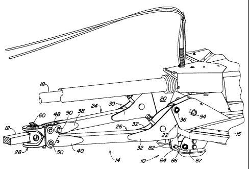
Referring now to FIG. 1, there is shown a front portion of a towed implement,
here
shown as a rotary cutter 10, a drawbar 12 of a tractor (not shown) and a
cutter hitch 14
coupling the cutter 10 to the drawbar 12. Provided for transmitting power from
a power take-
off shaft (not shown), at a rear location of the tractor and an input shaft
(not shown) of a gear
box carried at a top location of a deck 16 of the rotary cutter 10 for
distributing power for
driving cutter blades (not shown) is a shielded, telescopic power shaft 18.
Right- and left-hand, transversely spaced, upright hitch mounting brackets 20
and 22,
each in the form of transversely spaced parallel plates, are welded to
respective upper front
locations of the cutter deck 16 located equidistant from a longitudinal,
vertical center plane of
the rotary cutter 10. The hitch 14 includes separate upper and lower arm
sections 24 and
26, respectively, having their respective rear ends vertically pivotally
coupled to the brackets
20 and 22, and from which the arm sections converge forwardly (see also FIG.
5) to a ball
clevis 28 to which forward ends of the arm sections are individually pivotally
coupled.
Specifically, referring now also to FIG. 2, it can be seen that the rear ends
of the arm
sections 24 and 26 are defined by respective rear connecting portions 30 and
32, each being
in the form of a pair of transversely spaced, vertical, generally triangular
plates. The
connecting portion 30 is received between, and has an upper rear corner
pivotally
connected, as by a transverse mounting pin 34, to an upper forward location of
the plates of
the hitch mounting bracket 20. Similarly, the connecting portion 32 is
received between and
has an upper rear corner pivotally connected, as by a transverse mounting pin
36, to an
upper forward location of the plates of the hitch mounting bracket 22.
Referring now also to
FIG. 3, it can be seen that the forward ends of the arm sections 24 and 26 are
defined by
respective front connecting portions 38 and 40, each of which are in the form
of a pair of
transversely spaced straps, with the straps of the connecting portion 38 being
disposed
2
CA 02361640 2004-10-26
above, and in vertical alignment with, the straps of the connecting portion
40. The clevis 28
is made of identical, upper and lower halves 42 and 44, respectively, having
ring-like forward
ends and block-like rear ends. The clevis halves 42 and 44 are clamped to each
other by a
pair of fore-and-aft spaced bolts 46 extending vertically through the block-
like rear ends.
The straps of the front connecting portion 38 of the upper arm section 24
straddle, and are
pivotally coupled to the block-like rear end of the upper clevis half 42 by a
horizontal pivot
pin 48 located in a bore located in the clevis half 42 between the spaced
bolts 46. Similarly,
the straps of the front connecting portion 40 of the lower arm section 26
straddle, and are
pivotally coupled to, the block-like rear end of the lower clevis half 44 by a
horizontal pivot
pin 50 spaced vertically below the pivot pin 48. It is here noted that the
left-hand end of
each of the pins 48 and 50 includes a head defined by a washer welded to the
stem of the
pin.
As can best be seen in FIG. 4, the mounting pins 34 and 36, respectively, for
coupling the rear ends of the upper and lower arm sections 24 and 26 to the
hitch supports
20 and 22, define first and second horizontal axes that are spaced vertically
from each other
by the same distance that third and fourth horizontal axes, respectively
defined by the pivot
pins 48 and 50 coupling the front ends of the arm sections to the clevis
halves 42 and 44,
are spaced from each other. Thus, it will be appreciated that the separate arm
sections 24
and 26, together with the supports 20 and 22, and with the clevis 28 form a
four-bar linkage
which results in the clevis 28 remaining level throughout the vertical
pivoting of the arm
sections 24 and 26 during operation of the rotary cutter 10 over uneven
terrain.
Referring once again to FIGS. 2 and 3, it can be seen that the ring-shaped
forward
ends of the clevis halves 42 and 44 are respectively engaged with top and
bottom portions of
a ball 52. The clevis halves 42 and 44 are provided with respective
spherically shaped
surface portions (not shown) that are complementary to respective outer
surface portions of
the ball 52 so that the ball is captured by the clevis halves but is gripped
loose enough that
the clevis halves slide upon the ball surface. The ball 52 contains an opening
54 which is
rectangular in cross section and receives the rear portion of the tractor
drawbar 12. The
drawbar 12 is provided with a vertical hole which is aligned with a vertical
hole 58 extending
through the ball 52, with a hitch pin 60 being received in these aligned holes
so as to
connect the hitch 14 to the tractor and to provide a vertical axis about which
the hitch 14 may
pivot.
Referring now to FIGS. 1, 2 and 5, there is shown structure for effecting
raising or
lowering of the clevis 28, for accommodating tractor drawbars of different
heights, by
individually inducing a force for lifting or lowering the arm sections 24
andlor 26 about the
3
CA 02361640 2001-11-06
pivot pins 48 and 50. Specifically, extending horizontally between and welded
to the straps
making up the connecting portion 30 of the upper hitch arm section 24 is a rod
which defines
a stop 62. A bell crank 64, in the form of a-pair of parallel, generally
triangular plates, has a
first corner mounted for pivoting about the pivot pin 34 and includes a front
corner with the
plates straddling and being welded to a threaded cylindrical tube 66, which
receives a cap
screw 68 having its lower end engaged with the stop 62. A jam nut 70 is
received on the
screw 68 for holding the latter in a desired position of adjustment. The bell
crank 64 has a
lower rear corner pivotally attached to a clevis forming a forward end of a
fore-and-aft
extending leveling rod (not shown) having a rear end pivotally attached to a
lug fixed to a
transverse wheel axle (also not shown) pivotally mounted to a rear location of
the deck 16
and held in a desired disposition by a hydraulic motor, or the like. Thus, it
will be
appreciated that, as viewed in FIG. 2, raising of the hitch 28 from its
illustrated position is
permitted by withdrawing the screw 68 so as to allow upward movement of the
stop 62 about
the pin 34, while lowering of the hitch is permitted by advancing the screw 68
so that the
stop 62 engages the screw 68 at a lower location.
Similarly, a bell crank 72, in the form of a pair of parallel, generally
triangular plates
having an upper corner mounted for pivoting about the pivot pin 36, and having
a lower front
corner arranged with the plates straddling and being welded to a threaded
cylindrical tube
74, which receives a cap screw 76 having its lower end engaged with a stop 78
formed by a
rod extending horizontally between and welded to the plates forming the
connection portion
32 of the lower arm section 26. A jam nut 80 is received on the screw 76 and
serves to
retain it in a desired adjusted position. A lower rear corner of the bell
crank 72 is provided
with a pair of vertically spaced holes, one of which receives a pin 81 that is
captured
between the plates forming the bell crank 72 and pivotally attaches the bell
crank to a link
82, which is formed by a pair of parallel straps having upper ends located
above the pin 81
and pinned, as at 83, to a clevis forming a forward end of a second leveling
rod (not shown)
having a rear end coupled to a second lug fixed to the wheel axle at the rear
of the deck 16.
It is here noted that the pin 83 is captured between the plates forming the
bell crank 72 and
is located at a level approximately equal to that of the connection of the
lower rear end of the
bell crank 64 with the leveling rod on that side. The link 82 extends
downwardly from the pin
81 and has a lower end pivotally attached, as at a pin 84, to a short link 86
that extends fore-
and-aft and has its rear end received between, and pivotally attached, as by a
pin 87, to
lower projections of the hitch mounting bracket 22. Adjustment of the screw 76
results in
the hitch arm section 26, and hence the clevis 28, being raised or lowered in
a manner
4
CA 02361640 2001-11-06
similar to that effected by adjustment of the screw 68, as described above.
When it is desired to unhook the hitch 14 from the tractor drawbar 12, a jack
stand
(not shown) may be mounted to the clevis 28. For this purpose, a triangular
support plate
88, as can best be seen in FIGS. 1, 2 and 4, is mounted to the left-hand side
of the clevis 28
by the pins 48 and 50, it being noted that the welded washers defining the
heads at the left-
hand ends of the pins 48 and 50 serve to retain the plate 88 in place. Welded
to a rear
corner location of the plate is a jack stand mounting tube 90 which is
provided with a cross
hole 92 that serves to receive mounting hardware of the jack stand. Of
importance is the
fact that, due to being mounted on the pins 48 and 50, the plate 88 remains in
a constant
attitude throughout any vertical adjustments made for accommodating drawbars
of different
heights, with the tube 90 being oriented such that the jack stand, when
coupled to it, has a
substantially vertical disposition. A mounting tube 94 (see FIG. 1 ), similar
in construction to
the mounting tube 90, is provided on the left-hand plate of the support
bracket 22 for the
purpose of providing a location for storing the jack stand, in a substantially
horizontal
orientation, during operation of the rotary cutter 10.
5