Note: Descriptions are shown in the official language in which they were submitted.
CA 02361657 2001-08-03
WO 00/46486 PCT/AUOO/00066
1
CUTTING DEVICE
The present invention relates to an earth cutting device for excavation
purposes and is particularly, although not exciusively, concerned with
excavating hard rock. It will be convenient therefore, to describe the
invention
in relation to that application, although it is to be appreciated that the
invention
could have wider application.
Traditionally, excavation of hard rock in the mining and construction
industries, has taken one of either two forms, namely explosive excavation, or
rolling edge disc cutter excavation. Explosive mining entails drilling a
pattern of
holes of relatively small diameter into the rock being excavated, and loading
those holes with explosives. The explosives are then detonated in a sequence
designed to fragment the required volume of rock for subsequent removal by
suitable loading and transport equipment. The explosives are detonated once
all personnel are evacuated from the excavation site and the explosive process
is repeated cyclically, until the required excavation is complete.
The use of explosives for excavation is known to be dangerous, while it
is also environmentally unfriendly and results in damage to the country rock,
with the result that clearing of loosened rock pieces and the erection of
supports for the excavated surfaces is both dangerous and difficult.
Additionally, the cyclical nature of the process and the violent nature of the
rock
fragmentation has to date, prevented automation of the explosive process, so
that the modern requirement for continuous operation and increased production
efficiency has not been met. Moreover, the relatively unpredictable size
distribution of the rock product formed, complicates downstream processing.
Mechanical fragmentation of rock eliminating the use of explosives, has
already been achieved and is well known through the use of rolling edge-type
disc cutter technology. This technology has facilitated automation of the
excavation process including the benefit of remotely controlled excavation
machinery. However, rolling edge cutters require the application of very large
forces in order to crush and fragment the rock under excavation. For example,
the average force required per cutter is in the order of 50 tonnes and
typically,
CA 02361657 2001-08-03
WO 00/46486 PCT/AU00/00066
2
peak forces experienced by each cutter are more than twice than this. It is
common for multiple cutters to be arranged to traverse the rock in closely
spaced parallel paths, and 50 cutters per cutting array is common. Cutting
machinery of this kind can weigh upwards of 800 tonnes, thereby requiring
electrical power in the order of thousands of kilowatts for operation. As
such,
that machinery can only be economically employed on large projects, such as
water and power supply tunnels. Additionally, the excavation carried out by
such machinery is limited to a cross-section which is circular.
It is an object of the invention to overcome, or at least alleviate one or
more of the disadvantages associated with prior art cutting devices. It is a
further object of the invention to provide a cutting device of a rotary
cutting type,
that provides improved rock removal from a rock face and which is relatively
economical to manufacture and operate.
A rock excavating or cutting device according to the present invention
includes a disc cutter, and is characterised in that the disc cutter is driven
to
move in an oscillating and nutating manner. The disc cutter is driven to move
in
this manner about separate oscillating and nutating axes, which are angularly
offset from one another and intersect at a point ahead of the disc cutter. The
magnitude of nutating movement is directly proportional to the angle of offset
between the respective axes and generally that angle will be relatively small,
such that the point of intersection between the axes is a relatively long way
ahead of the disc cutter. In some arrangements, the point of intersection will
approach infinity such that the amount of nutating movement is very small.
Preferably, the disc cutter is caused to oscillate and nutate sinusoidally
through
a relatively small amplitude and at a very high frequency, such as about
3000RPM.
The motion by which the disc cutter is driven, is such as to cause tensile
failure of the rock, so that chips of rock are displaced from the rock surface
under attack by the disc cutter. Here, the invention differs from rolling edge
disc cutters, which apply force normal to the rock face to form lateral cracks
that
produce rock chips.
The force required to produce a tensile failure in the rock to displace a
rock chip according to the device of the invention, is an order of magnitude
less
CA 02361657 2001-08-03
WO 00/46486 PCT/AUOO/00066
3
than that required by the known rolling edge disc cutters to remove the same
amount of rock, so that the device of the invention is far more efficient in
respect of energy requirements. Additionally, the device of the invention
produces relatively little dust.
The device of the invention employs a reaction mass of sufficient
magnitude to absorb the forces applied to the rock by the disc cutter during
each cycle of oscillation and nutation, with minimum or minor displacement of
the device, or the structure supporting the device. Because the device applies
a load suitable to cause tensile failure of the rock, instead of crushing the
rock,
the force applied to the rock is substantially reduced, such that a
corresponding
reduction in the required reaction mass compared to known rock excavation
machinery can also be adopted. The device of the invention as mounted to the
support structure is preferably arranged that the reaction mass can absorb the
cyclic and peak forces experienced by the disc cutter, while the support
structure provides a restoring force relative to the average force experienced
by
the disc cutter.
The disc cutter of the cutting device preferably has a circular, rock
engaging periphery, which is formed of a wear resistant material, such as
hardened steel or tungsten carbide. Alternatively, the disc cutter can include
a
plurality of cutting tips, preferably of tungsten carbide, which are fixed to
the
circular rock engaging periphery thereof. Alternatively, the disc cutter can
include a removable cutting disc that likewise is formed to have a circular
rock
engaging periphery of a wear resistant material, such as that described above.
The periphery of the disc cutter is arranged to be rotatable relative to the
oscillating and nutating movement thereof, so that the periphery can roll
against
the rock surface under attack. In this manner, all parts of the cutting
periphery
edge are progressively moved out of contact with the rock and allowed to cool,
and wear is evenly distributed. Because the contact force is relatively low,
the
wear rate is reduced compared to the rolling edge type of cutter.
The oscillating movement of the disc cutter can be generated in any
suitable manner. In a preferred arrangement, the disc cutter is mounted for
rotary movement on a drive shaft that includes a driven section which can be
driven by suitable driving means and a mounting section on which the disc
CA 02361657 2001-08-03
WO 00/46486 PCT/AUOO/00066
4
cutter is mounted. The axis about which the driven section rotates is
angularly
offset from the axis of the mounting section and in this arrangement, the disc
cutter can move, as required, in a nutating manner simultaneously as it
oscillates.
In a preferred arrangement, the disc cutter is mounted on one end of the
shaft, which end comprises the mounting section and which extends from the
shaft at an angle offset from the longitudinal axis of the shaft. The offset
end
may be formed integral with the shaft, or may be attached thereto and the end
may include means to attach the disc cutter thereto. Those means allow for
relative rotary movement, between the disc cutter and the mounting . The disc
cutter may for example, be mounted on the mounting section by bearings, such
as tapered roller bearings, to allow relative rotation therebetween.
The device of the invention can operate to cut or excavate very hard
rock, with greatly reduced applied force and much higher output per disc
cutter,
while using less power per unit volume of rock removed. Thus the device can
be mounted on a vehicle of significantly reduced weight and cost, compared,
for example, to rolling edge disc cutters, while providing much greater
flexibility
in the geometry of excavation.
The cutting device of the invention is not restricted to a single disc cutter,
but can include more than one. For example, the cutting device may include
three disc cutters arranged along the same plane, but angled at approximately
450 to each other. Such an arrangement can produce a cut face of a particular
shape, while the speed at which rock is removed is greatly increased. In this
arrangement, each of the three disc cutters can be driven by the one drive
means, or they may be driven by separate drive means. The use of multiple
disc cutters is particulariy useful for long wall operations.
The device of the invention typically requires substantially reduced
applied forces relative to known rock excavating machinery. A reduction at
least in respect of normal forces, in the order of one tenth is envisaged.
Such
low forces facilitates the use of a support structure in the form of an arm or
boom, which can force the edge of the disc cutter into contact with the rock
at
any required angle and to manipulate the position of the disc cutter in any
direction. In particular, in relation to long wall mining, the disc cutter, or
array of
CA 02361657 2001-08-03
WO 00/46486 PCT/AUOO/00066
disc cutters, may be mounted to traverse the length of the long wall face and
to
be advanced at each pass. Advantageously, the invention provides for entry of
the disc cutter into the rock face from either a previously excavated drive in
a
long wall excavation, or from pre-bored access holes, or by attacking the rock
5 at a shallow angle to the face until the required depth for the pass is
achieved.
With the disc cutter mounted on a movable boom, the disc cutter can be moved
about the rock face to excavate that face at any desired geometry.
In still a further arrangement, a pair of disc cutters may be mounted on
separate booms and the disc cutters are swept in an arc across the rock face,
continually removing successive layers of rock from the face, and forming a
cusp between adjacent concave sections. The cusp provides an entry point for
the disc cutter on the return pass thereof.
The cutting device of the invention is suitable for a range of cutting and
mining operations and machinery, such long wall mining, mobile mining
machines, tunnelling machines, raise borers, shaft sinkers and hard rock
excavation generally.
The attached drawings show an example embodiment of the invention of
the foregoing kind. The particularity of those drawings and the associated
description does not supersede the generality of the preceding broad
description of the invention.
Figure 1 shows a part cross-sectional view of a cutting device according
to the invention.
Figure 2 is an enlarged view of the cutting device of Figure 1.
Figure 3 is a schematic view of the action of the cutting device in
excavating a rock face.
Figure 4 shows a further embodiment of the invention mounted on a
boom.
Figure 5 shows a further embodiment of the invention.
Figure 6 shows the application of the invention to sweep excavations.
Figure 7 shows an alternative embodiment of the invention.
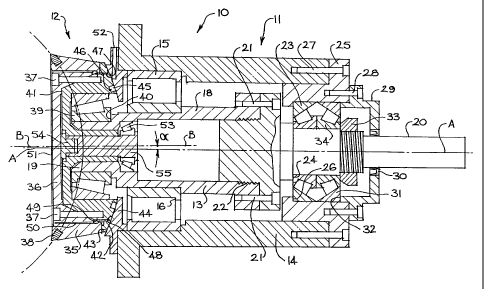
Figure 1 is a cross-sectional view of a cutting device according to the
invention. The cutting device 10 includes a mounting assembly 11 and a rotary
disc cutter 12. The mounting assembly 11 includes a mounting shaft 13 which
CA 02361657 2001-08-03
WO 00/46486 PCT/AUOO/00066
6
is rotatably mounted within a housing 14, that can constitute or be connected
to
a large mass for impact absorption. The housing 14 thus, can be formed of
heavy metal or can be connected to a heavy metallic mass. The shaft 13 is
mounted within the housing 14 by a bearing 15, which can be of any suitable
type and capacity. The bearing 15 is mounted in any suitable manner known to
a person skilled in the art, such as against a stepped section 16.
The housing 14 can have any suitable construction, and in one form
includes a plurality of metal plates fixed together longitudinally of the
shaft 13.
Such an arrangement is shown in Figure 2, and with this arrangement,
applicant has found that a plurality of iron plates 17a and a single lead
plate
17b provides effective impact absorption based on weight and cost
considerations.
The shaft 13 is mounted for rotating motion about a central longitudinal
axis AA. The shaft 13 includes a driven section 18 and a mounting section 19.
The driven section 18 is connected to drive means 20 at the end thereof remote
from the mounting section by any suitable connectors, such as heavy duty
threaded fasteners 21, while a seal 22 is applied between the facing surfaces
of
the mounting section and the drive means.
The drive means 20 can take any suitable form and the means shown in
Figure 1 is a shaft that may be driven by a suitable engine or motor. The
drive
means 20 is mounted within the housing 14 by bearings 23, which are tapered
roller bearings, although other types of bearings could also be employed. The
bearings 23 are mounted against a stepped section 24 of the drive means 20
and against a mount insert 25 which is:afso stepped at 26. The mount insert 25
is fixed by threaded connectors 27 to the housing 14 and fixed to the mount
insert 25 - by further threaded connectors 28 is a sealing cap 29 which seals
against the drive means 20 by seals 30. The sealing cap 29 also locates the
outer race 31 of the bearings 23 by engagement therewith at 32, while a
threaded ring 33 locates the inner race 34.
The mounting section 19 is provided for mounting of the disc cutter 12
and is angularly offset from the axis AA of the driven section 18, which
generally will be approximately normal to the rock face being excavated. The
axis BB of the mounting section 19 is shown in Figure 1 and it can be seen
that
CA 02361657 2001-08-03
WO 00/46486 PCT/AUOO/00066
7
the offset angle a is in the order of a few degrees only. The magnitude of the
offset angle a determines the size of the oscillating and nutating movement of
the disc cutter 12 and the angle a can be arranged as appropriate.
The disc cutter 12 includes an outer cutting disc 35 that is mounted on a
mounting head 36 by suitable connecting means, such as threaded connectors
37. The outer cutting disc 35 includes a plurality of tungsten carbide cutting
bits
38 which are fitted to the cutting disc in any suitable manner. Altematively,
a
tungsten carbide ring could be employed. The outer cutting disc can be
removed from the cutting device for replacement or reconditioning, by removing
the connectors 37.
The disc cutter 12 is rotatably mounted on the mounting section 19 of
the mounting shaft 13. The disc cutter 12 is mounted by a tapered roller
bearing 39, that is located by a step 40 and a wall 41 of the mounting head
36.
An inclined surface 42 of the mounting head 36 is disposed closely adjacent a
surface 43 of a mounting insert 44. The surfaces 42 and 43 are spaced apart
with minimum clearance to allow relative rotating movement therebetween and
the surfaces have a spherical curvature, the centre of which is at the
intersection of the axes AA and BB.
A seal 45 is located in a recess 46 of the surface 42 to seal against
leakage of lubricating fluid from between the mounting shaft 13, and the
housing 14 and the disc cutter 12. A channel 47 is also provided in the
surface
42 outwardly of the seal 45 and ducts 48 connect the channel 47 to a further
channel 49 and a further duct 50 extends from the channel 49 to the front
surface 51 of the outer cutting disc 35. Pressurised fluid can be injected
into
the various channels and ducts through the port 52 and that fluid is used to
flush the underside of the cutting disc 35 as well as the relative sliding
surfaces
42 and 43.
The disc cutter 12 is rotatably mounted to the mounting section 19 of the
mounting shaft 13 by the tapered roller bearing 39 and by a further tapered
roller bearing 53. The bearing 53 is far smaller than the bearing 39 for the
reason that the large bearing 39 is aligned directly in the load path of the
disc
cutter and thus is subject to the majority of the cutter load. The smaller
bearing
53 is provided to pre-load the bearing 39.
CA 02361657 2001-08-03
WO 00/46486 PCT/AU00/00066
8
The bearing 52 is mounted against the inner surface of the mounting
shaft 13 and the outer surface of a bearing loading facility, comprising a nut
54
and a pre-loading shaft 55. Removal of the outer cutting disc 35 provides
access to the nut 54 for adjusting the pre-load of the bearing 53.
The nutating movement of the disc cutter 12, occurs simultaneously with
the oscillating motion and that nutating movement is movement in which a point
on the cutting edge of the disc cutter is caused to move sinusoidally, in a
cyclic
or continuous manner as the disc cutter rotates. This movement of the disc
cutter applies an impact load to the rock surface under attack, that causes
tensile failure of the rock. With reference to Figure 3, it can be seen that
the
motion of the disc cutter 12 brings the cutting tip or edge 58 into engagement
under the oscillating movement at point 59 of the rock 56. Such oscillating
movement results in travel of the disc cutter 12 in a direction substantially
perpendicular to the axis AA. The provision of simultaneous nutating
movement causes the cutting edge 58 to strike the face 59 substantially in the
direction S, so that a rock chip 60 is formed in the rock as shown. Future
chips
are defined by the dotted lines 61. The action of the disc cutter 12 against
the
under face 59 is similar to that of a chisel in developing tensile stresses in
a
brittle material, such as rock, which is caused effectively to fail in
tension.
The direction S of impact of the disc cutter against the rock under face
59 is reacted through the bearing 39 and the direction of the reaction force
is
substantially along a line extending through the bearing 39 and the smaller
bearing 53.
In a cutting device according to the invention, the mass of the disc cutter
is relatively much smaller than the mass provided for load absorption
purposes.
The load exerted on the disc cutter when it engages a rock surface under the
oscillating/nutating movement, is reacted by the inertia of the large mass,
rather
than by the support structure.
The cutting device of the invention is preferably mounted for movement
into the rock being excavated. Thus, the device can be mounted for example,
on wheels or rails and it is preferred that the mounting facility be arranged
to
react the approximate average forces applied by the disc cutter, while the
large
absorption mass reacts the peak forces.
CA 02361657 2001-08-03
WO 00/46486 PCT/AUOO/00066
9
The various bearings employed in the invention can be of any suitable
kind, but preferably they are anti-friction roller bearings, and can be
hydrodynamic or hydrostatic bearings.
The present invention can be applied to a wide variety of cutting devices
and one such device is shown in Figure 4. In this figure, the cutting device
is
pivoted on a boom so that he disc cutter can be manoeuvred about the boom
pivot point to excavate a rock face.
Figure 5 shows a different arrangement in which three disc cutters
extend from the cutting device and these cutters are aligned along the same
plane and are oriented at an angle to each other, the angle being
approximately
45 . Each of the disc cutters is arranged for oscillating and nutating
movement
as previously described.
Figure 6 shows an arrangement of two cutting devices 300 and 400
which pivotally arranged on respective booms 301 and 401 (such as that shown
in Figure 4), and in which the disc cutter 302 and 402 of each device is
arranged to sweep in an arc across the rock face 500 being excavated in a
first
direction D, and having completed that sweep, return in the reverse direction
D2, with each sweep of the disc cutters removing a layer of the rock face 500.
Entrance of the disc cutters into the rock for each successive pass, may be at
the cusp 502 between adjacent concave sections 503 formed by the sweep of
each disc cutter. This method provides a bore 501 as shown.
Figure 7 shows a further alternative arrangement of the present
invention, which has generally the same operating characteristics as the
cutting
device of Figure 1. Therefore, the description relating to Figure 7 will
relate to
areas of difference only.
In Figure 7, the cutting device 600 includes a bearing arrangement
between the mounting plate 601 and the cutting disc 602, and specifically
between an annular flange 603 of the cutting disc and the internal walls of an
annular slot 604 formed in the mounting plate.
The bearing arrangement of Figure 7 includes annular bearings 605 and
606 which, in the embodiment illustrated, are anti-friction, water lubricated
bearings. Water lubrication is provided through a conduit 607 that
CA 02361657 2001-08-03
WO 00/46486 PCT/AUOO/00066
communicates with an annular space 608 to distribute lubricating water to each
of the bearings 605, 606.
The bearings 605, 606 are provided to bear axial thrust loading, so that
the remaining bearings of the cutting device 600 are subject only to radial
5 loading. The arrangements described earlier, such as that of Figure 1,
employ
tapered roller bearings to accommodate axial thrust loading but in the Figure
7
embodiment, non-tapered roller bearings can generally be employed instead.
See for example the bearings 609, 610 of Figure 7. This arrangement is
considered to have superior performance compared to the earlier described
10 arrangements, as the tapered roller bearings employed in those arrangements
lacked the ability to completely bear the thrust loadings that the device 600
will
experience. Tapered roller bearings may still be employed if considered
desirable and thus bearings 611 are of the tapered roller bearing kind. The
annular bearings 605, 606 can be of any suitable shape and conveniently, the
shape of those bearings can be such as to facilitate the nutating movement of
the cutting disc 602.
A further feature of the Figure 7 arrangement is the use of cutting disc
drive means between the cutting disc 602 and the mounting plate 601. That
drive means is operable to drive the cutting disc 602 in the reverse direction
compared to the direction of rotation of the drive shaft 612. Reverse rotation
of
the cutting disc 602 is desirable to minimise or eliminate relative movement
between the cutting edge 613 of the cutting disc 602, and the rock face when
the cutting edge 613 engages the rock face. Reverse rotation preferably
causes the cutting edge 613 to roll against the rock face. As such, wear of
the
cutting edge is limited to that produced by the impact of the edge engaging
the
rock face, and little or no wear is experienced through frictional drag or
scraping
movement between the edge 613 and the rock face.
The drive means discussed above can comprise a gear arrangement
and in Figure 7, that may be provided between the mounting plate 601 and the
cutting disc 602 on the ring 614 that is-accommodated within the slot 615. The
gear arrangement 616 operates so that rotation of the mounting plate 601 by
the drive shaft 612 drives the cutting disc 602 in the reverse direction. It
will be
appreciated that the mounting plate 601 is not directly driven by the drive
shaft
CA 02361657 2001-08-03
WO 00/46486 PCT/AUOO/00066
11
612, but that rotation of the mounting plate 601 occurs by virtue of drag
through
the various bearings 609, 610 and 611. That drag will eventually cause the
mounting plate 601 to rotate at or about the same speed as the drive shaft
612,
nominally about 3000 RPM, in the absence of any load applied in the reverse
direction. In the same manner, in the absence of drive means to drive the
cutting disc 602 in the reverse direction and in the absence of other loads,
particularly loads resulting from engagement of the cutting edge 613 with the
rock face, the disc 602 will likewise be driven at or about the same speed as
the drive shaft. Thus, in those circumstances, when the cutting edge 613 of
the
rotating cutting disc 602 engages the stationary rock face, it experiences a
substantial drag load tending to slow the rotation of the disc. In practice,
the
cutting disc can be slowed, almost instantaneously, from about 3000 RPM to
about 40RPM, with significant wear or damage resulting to the cutting edge
613. By employing drive means to drive the cutting disc in the reverse
direction, that wear or damage can be largely reduced or eliminated.
In order to minimise or eliminate drag of the cutting edge 613 against the
rock face as described above, the pitch circle diameter of the gear
arrangement
616 should be the same as the diameter of the cutting edge 613.
The gear arrangement 616 described above is not the only arrangement
by which reverse rotation of the cutting disc 602 can be achieved. Other
arrangements could equally apply and therefore, the invention is not
restricted
to the arrangement described. It is also to be appreciated that the drive
means
described in relation to Figure 7 could equally be embodied in other
arrangements according to the invention.
The cutting device of the present invention is considered to provide more
cost efficient rock cutting, because the device can be built at a fraction of
the
weight of known rotary cutting machinery. It is envisaged that the cutting
device of the invention including the support arm, can be manufactured to have
a total weight of approximately 20 tonne. This means that the device will be
far
cheaper to manufacture and run compared to the known rotary cutting
machinery. The weight reduction is principally due to the enhanced rock
cutting
which results from the combination of oscillating and nutating movement of the
disc cutter. Thus, the rock cutting device is subject to reduced impact
loading
CA 02361657 2001-08-03
WO 00/46486 PCT/AUOO/00066
12
and therefore requires substantially less facility for impact absorption.
Additionally, the shocks produced by the cutting process are relatively minor
and thus these cause negligible damage to the country rock, and thus lessen
the likelihood of rock falls and reduce amount of support necessary for
excavated surfaces. Moreover, because of the overall weight of the device and
the magnitude of the shocks produced, the device can be mounted on a vehicle
for movement into the excavated surface.
The invention described herein is susceptible to variations, modifications
and/or additions other than those specifically described and it is to be
understood that the invention includes all such variations, modifications
and/or
additions which fall within the spirit and scope of the above description.