Language selection

Search

Patent 2361945 Summary

Third-party information liability

Some of the information on this Web page has been provided by external sources. The Government of Canada is not responsible for the accuracy, reliability or currency of the information supplied by external sources. Users wishing to rely upon this information should consult directly with the source of the information. Content provided by external sources is not subject to official languages, privacy and accessibility requirements.

Claims and Abstract availability

Any discrepancies in the text and image of the Claims and Abstract are due to differing posting times. Text of the Claims and Abstract are posted:

  • At the time the application is open to public inspection;
  • At the time of issue of the patent (grant).
(12) Patent: (11) CA 2361945
(54) English Title: TANK WITH CARRYING FLANGE
(54) French Title: RESERVOIR AVEC RAINURES D'ASSUJETISSEMENT
Status: Term Expired - Post Grant Beyond Limit
Bibliographic Data
(51) International Patent Classification (IPC):
  • B65D 88/12 (2006.01)
  • B65D 81/00 (2006.01)
  • B65D 88/08 (2006.01)
  • B65D 90/00 (2006.01)
(72) Inventors :
  • EISNER, NEIL (Canada)
(73) Owners :
  • BOURGAULT INDUSTRIES LTD.
(71) Applicants :
  • BOURGAULT INDUSTRIES LTD. (Canada)
(74) Agent: MLT AIKINS LLP
(74) Associate agent:
(45) Issued: 2004-07-13
(22) Filed Date: 2001-11-13
(41) Open to Public Inspection: 2003-05-13
Examination requested: 2001-11-13
Availability of licence: N/A
Dedicated to the Public: N/A
(25) Language of filing: English

Patent Cooperation Treaty (PCT): No

(30) Application Priority Data: None

Abstracts

English Abstract

A tank comprises recesses defined along opposite lower side portions thereof from a front of the tank to a rear thereof such that an upper portion of the tank extends laterally over the recesses. A downward oriented flange is located at a top of at least one recess in proximity to an outer edge of the upper portion, the flange thereby providing a gripping location for carrying the tank.


French Abstract

Réservoir comprenant des rainures le long de parties inférieures latérales opposées de l'avant à l'arrière du réservoir de sorte qu'une partie supérieure du réservoir s'étend de manière latérale au-dessus des rainures. Un rebord orienté vers le bas est situé au-dessus d'au moins une rainure près d'une bordure externe de la partie supérieure; le rebord sert de prise pour transporter le réservoir.

Claims

Note: Claims are shown in the official language in which they were submitted.

-Page 12-
CLAIMS:
We claim:
1. A tank comprising recesses defined along opposite
lower side portions thereof from a front of the tank
to a rear thereof such that an upper portion of the
tank extends laterally over the recesses; and a
downward oriented flange located at a top of at least
one recess in proximity to an outer edge of the upper
portion, the flange thereby providing a gripping
location for carrying the tank.
2. The apparatus of Claim 1 wherein the flange extends
down into the recess.
3. The apparatus of Claim 1 wherein the flange is formed
by a groove extending from a top of the recess up into
the tank.
4. The tank of Claim 1 wherein an outer surface of the
flange is aligned with an outer surface of the upper
portion.

-Page 13-
5. The tank of any one of Claims 1 - 4 wherein the
recesses are formed by upright substantially parallel
sidewalls extending from the front of the tank to the
rear of the tank, and wherein the flange extends
around the tank from one end of a corresponding side
wall to an opposite end of the corresponding side
wall.
6. The tank of any one of Claims 1 - 5 wherein the flange
defines a hollow channel, and wherein any liquid in
the channel drains into the tank when the tank is
oriented horizontally.
7. The tank of Claim 5 wherein the flange defines a
hollow channel passing through the corresponding side
wall at each end of the flange.
8. The tank of any one of Claims 1 - 7 wherein the upper
portion of the tank has a vertically oriented
cylindrical shape having a first diameter, and wherein
the tank comprises a lower portion having a vertically
oriented cylindrical shape concentric with the upper

-Page 14-
portion and having a second diameter smaller than the
first diameter such that the upper portion extends
over the lower portion thereby forming the recesses
along the opposite lower side portions of the tank.
9. The tank of any one of Claims 1 - 7 wherein the tank
is generally rectangular in shape and wherein a lower
portion of the tank is narrower than the upper portion
thereof such that the upper portion extends over the
lower portion thereby forming the recesses along the
opposite lower side portions of the tank.
10. The tank of any one of Claims 1 - 9 wherein the tank
comprises a cylindrical upper portion and a modified
cylindrical lower portion vertically aligned with a
front and a rear of the upper portion and having
flattened parallel side walls forming the recesses
under opposing sides of the upper portion.
11. The tank of any one of Claims 1 - 10 wherein the tank
is made from rotationally molded plastic.
12. A tank comprising:

-Page 15-
a cylindrical upper portion;
a modified cylindrical lower portion vertically
aligned with a front and a rear of the upper portion
and having flattened parallel side walls forming
recesses under opposing sides of the upper portion;
a downward oriented flange located at a top of at
least one recess in proximity to an outer edge of the
upper portion, the flange thereby providing a gripping
location for carrying the tank.
23. The tank of Claim 12 wherein the flange extends down
from the upper portion into the at least one recess.
14. The tank of Claim 13 wherein an outer surface of the
flange is aligned with an outer surface of the upper
portion.
15. The tank of any one of Claims 12 - 14 wherein the
flange extends around the tank from one end of a

-Page 16-
corresponding side wall to an opposite and of the
corresponding side wall.
16. The tank of claim 15 wherein the flange defines a
hollow channel passing into the tank at each end of
the flange.
17. The tank of claim 12 wherein:
the upper portion comprises a cylindrical upper wall
oriented about a substantially vertical axis and a
cover; and
the lower portion comprises:
lower front and rear arced walls vertically
aligned with and joined at upper edges thereof to
the cylindrical upper wall and joined at lower
edges thereof to a floor;
substantially parallel left and right upright
side walls joined at each end thereof to the

-Page 17-
lower front and rear arced walls and at lower
edges thereof to the floor; and
left and right substantially horizontal panels,
each panel joined on an inside edge thereof to
the top edge of a corresponding upright side wall
and having an outside edge operatively connected
and sealed to the upper wall.
18. The tank of claim 17 wherein the flange extends down
from a horizontal panel.
19. The tank of Claim 18 wherein are outer surface of the
flange is aligned with an outer surface of the
cylindrical upper wall.
20. The tank of Claim 18 wherein the flange extends down
from a mid-point of the horizontal panel.
21. The tank of Claim 17 wherein the flange is foamed by a
groove extending up from a horizontal panel into the
upper portion of the tank.

-Page 18-
22. The tank of any one of claims 12 - 21 wherein the tank
is made from rotationally molded plastic.

Description

Note: Descriptions are shown in the official language in which they were submitted.


CA 02361945 2001-11-13
Pa~''r Z._
Tax wr2~i CARRY?Na Fi~GR
This invention is iri tht field of tanks and in particult~r
tanks that arc manually carried from one location to
another.
Small tanks that fit in pick-up truck boxes are popular. A
problem with such boxes is that the tank must fit between
the wheel wells on the bax, with the result that in order ..
to carry the desired load of 1000 ~ 1200 litres of water,
for instance, a conventional Cylindrical or rectangular

CA 02361945 2001-11-13
F&K 1D46-03-01
- Page 2 -
tank must be higher than is desired. It is generally
desired to carry a load as low as possible to increase
stability during transport. Modified tanks have thus been
developed wherein a lower portion fits between the wheel
wells and an upper portion e~stends over the wheel wells.
vertically oriented cylindrical tanks rotationally molded _
from plastic are commonly modified far use in pick-up txuek
boxes by providing a flattened portion along each side and
part way up the vertical side wall of the ttink to prOVide a
recCSS accommodating the wheel wells in the box. Such a
design allows for provision of a relatively low profile
tank with a capacity of 1000 - 1206 litres, which is about
the maximum load for such trucks.
There are also known "mushroom" shaped tanks which have a
smaller diameter lower portion and ~.axger diameter upper
portion. Recesses are provided under the ugper portion by
virtue of the fact that the lower portion has t~ smaller
diameter. RCCtangu~,ar ~.anl~s can also be modified to
grovide a recess in a lower portion to accommodate the
wheel wells.

CA 02361945 2001-11-13
F&K 1046-03-O1
- gage 3 -
Such conventionally modified tanks are generally made from
plastic so they are qu~.te light and are commonly lifted in
and out of the truck box by hand. The shape Qf such
existing modified tanks however does not provide any
location where those carrying such a tank can securely grip
it, with the result tht~t carrying the tank is an awkward
task. l~dding handles requires providing holes through the _
tank which oan cause leaks. Handles also exte~ad from the
tank and are subject to being broken.
SUMMARY OF T~iB INVENTIOT.I
It is the object of the present invention to provide a taxlk
having a convenient carrying flaxa,ge that allows a person to
securely grip the tax~.k for manual movement of the tank
wherein the flange is incorporated into the tank stxwetuxe
to reduce the possibility of leaks.
It is a further object of the invention to provide such a
tank that is particularly adapted for use in pick-up truck
boxes, that is economically manufactured from rotationally
molded--plastic, and that will readily drain any liquid
contained therein.

CA 02361945 2001-11-13
F&K 1046-03-Ol
- Page 4 -
The invention provides, in one aspect, a tank comprising
rece9ses defined along opposite lower side portions thereof
from a front of the tanlt to a rear thereof such that an
upper portion of the tank extends laterally over the
recesses. A downward oriented flange is located at a top .
of at least one recess in proximity to an outer edge of the _
upper portion, the ~lan<3e thereby providing a gripping '
location for carrying the tank.
In a second aspect the W vantiori prOVxdCS a tank comprising
a cylindrical upper portion and a modified cylindrical
lova~cr portion verticall~r aligned with a front and a rear of
the upper portion and having flattened parallel side walls
forming recess~s under opposing sides of the upper portion.
A d4wnward oriented flange is located txt a top of at least
one recess in proximity to an outer edge of the upper
portion, the flange thereby provid~.z~g a gripping location
for carrying the tarok.
The flange provides a lQCation that can readily be gripped
by a person for carrying. In conventional tanks the pexsox~
has only a right angle corner to grip. As the tanks are

CA 02361945 2001-11-13
F&K 104fi-03-Dl
- Page 5 -
generally plastic, the sux'face is smooth and difficult to
grip. The flange Can be relatively short, or can extend
around the curved wall of the upper portion above the
recess to provide a long grip location.
when the tank is made by rotationally molding plastic, the
flange will define a channel inside the tank. The flange _
caxx be formed so tk~,at the flange extends down in to the
recess, and the channel is formed inside the flange_ E
Similarly, the flange can be formed by a groove extending
~p from the recess into the tank. Here the flange is
formed between the groove and the outside wall, and the
channel is again irls~.de the flange. In either case, the
tank is Constructed so that this chaxlnel passes into the
tank to properly dr~ein any liquid from the channel so that
in ordinary use no pockets of liquid are left in the tank.
DBSCRTPTION OF THE Dli,~l~nTINGB t
While the invention is claimed in the concluding portions
hereof, pr~ferred embodiments are provided in the
accompanying detailed description which may be best
understood in conjunction with the acoompanying diagrams

CA 02361945 2001-11-13
F&K 1044-03-01
- Page 6 -
where like parts in each of the several diagrams are
labeled with like numbers, and where:
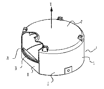
Fig, 1 is a side view of an embodiment of the W vtritidn;
Fig. 2 is a crosss-sectional view of the embodiment of k'~.g.
i; ,
Fig. 3 is a cut-away ~aerspective view of the embodiment of d
Fig. l;
lrig_ 4 is a schematic cro~~-GCCtiBn view Cf an alternate
f 1 ange
Fig. 5 is a schematic cross-sectional. view of an embodiment
similar to that o~ Figs. 1 - 3 where the flange is formed
by a groove extending up from the reCeas;
Fig. 6 is a rear view of a rectangu7.ax tank embodying the
invention;
Fig. 7 is a side view of the embodiment of Fig. 6.

CA 02361945 2001-11-13
1~&K 1046-43-O1
- Page 7 -
DETAILED DSSCRIPTZON OF T8E ILLUSTRATED 8M'BODIMENTSi
Figs. 1 - 3 illustrate a tank 1 of the invention. The tank
1 has a cylindrical upper portion 3 comprising a
cylindrical upper wall 5 oriented about a substantially
vertical. axis v and a cover 7. The tank 1 also has a
modifi~d cylindrical lower portion 9 that is vertically _
aligned with a ~ront and a rear o~ the upper portion 3 and
has flattened parallel side walls 11 forming recesses 13
under opposing sides of the upper portion 3_ These
recesses 13 accommodate the wheel wells of a standard pick-
up truck box, as is known in the art. Conventional drains,
Lids, and so forth are also illustrated.
The lower portion 9 Compx'ises lower frpnt anti rear arced
walls 15 vertically aligned with and joined at upper edges
thereof to the upper cylindriCal.wall 5 and joined at lower
edgee thereof to a floor 17_ The lower portion 9 further
comprises, to form the recesses 13, substantially parallel
left and right upright side walls 11 joined at each end
thereof to the lower front and rear arced walls 15 and at
lower edges thereof t4 the flQQr 17. The upright side
walls 11 can be curved or ribbed to add strength, but in

CA 02361945 2004-05-06
F&K 1046-03-O1
- Page $ --
any event are oriented upr~.gkzt to form the required recess
to accommodate wheel wells of a truck box.
The lower portion further Comprises, to fall the top of the
recesses 13, left and right substantially horizontal panels
7.9, each panel 19 joirxed on an inside edge thereof to the
top edge of a corresponding upright side wall 21 and having
an outside edge operatively cox~ected and sealed to the
upper wall 5.
A flange 2o extends down from the upper portion 3 of the
tank 1 into each recess 13. The outer surface of the
flange 20_is aligned with the outer surface of the upper
wall 5. ~'he flange 20 extends around the tank 1 from one
end of the side wall 11 to the opposite end thereof_ The
flange 2o provides a convex~iexxt location where a person can
grip the tank 1. by wrapping his fingers around the flar~ge
20.
_l.ne.._~~'l~rszra~eu GcCiISc ~-3tt -ma'QC "'LWOUi itn.:u=u~ul~i~d°-
~ria~i.ic.:.
This process results in the flange 2d defining a hollow
channel 27.. The tank 1 is constructed so that the channel
21 passes thxough the corresponding side wall 7.1 at eacia

CA 02361945 2001-11-13
P&~C 7.044-93-01
- Page 9 -
end of the flange 20. Any liquid in the channel 21 is thus
free to flow out the end of the charnel 2i and into the ..
bottom of the tank 1 and out a drain or the like. The
illustrated construction prevents liquid from gathering in
the chaxanel 21.
Fig. ~ illustrates an alternate ~lange zo extending doom
from a trim,-point of the panel 29 into the reoess 13, ra.thex' .'
than being flush with the upper wall 5. The flange 20 can
be relatively Bhort, providing gx~.p fcar only one hand, or
longer if desired. The flange 20 of Fig. 4 1e sQ~.~.d to
pxevent liquid from gathering, as no channel is provided
through the ~idewall 11.
Fig. 5 illustrates an embodiment a:Lmilar to that of gigs. 1
- 3 with a flange 20 that is provided by a groove 27 in
panel 19 extending from the top of the recess i3 up into
the upper portion pf the tank 1. The groove 27 thus forms
the flange 20. In this embodiment the flange 20 does not
extend down into the raoeGS Z3.
Although it is contemplated that the tank 1 will, in most
instances, be the modified cylindrical shape illustrated in

CA 02361945 2001-11-13
F&K 1046-03-O1
- Page 10 -
Figs. Z - 3, the tank 1 cax~ be virtually any shape, such as
mushroom, rectangular, oval, and so forth. In any of these ,_
shapes the tank 1 comprises, as illustrated in Figs. 6 and
7 for a rectangular tank, recesses 13 defined along
opposite lower side portions 38 of the tank 1 from a front
1A of the tank 1 to a rear 18 thereof such that an upper .-.
portion 3~ of the tank s extends laterally aver the _
recesses 13. A dowx~.ward oriented tlange 30 is located at a :'
top of the recesses 13 in proximity to an outer edge 35 of r~
the upper portion 33 to provide a gripping location for
carx'ying the tank 1 by hand.
Zn the embodiment of Figs- 6 and 7, the flange 30 is formed
by providing a groove 37 exte7r~ding up from the top of the
recess 13 into the upper portion 33 of the tank 1, In
order to drain properly, the flange 3o can be solid. If a
hallow channel is formed as in the embodiments above, the
channel should extend along the front or rear of the upper
portion and into the tank 2.
ThC foregoing is considered as illustrative only of the
principles of the invention. Further, since n,~merous
changes and modifications will readily occur to those

CA 02361945 2001-11-13
F&K 1046-03-O1
Page 11 -
skilled in the axt, it is not desired to limit the
invention to the exact construction and operation shoran and
described, and accordingly, all such suitable changes or
modifications in structure or operation which may be
resorted to are intGndGd to fall within the scope of the
claimed invention.

Representative Drawing
A single figure which represents the drawing illustrating the invention.
Administrative Status

2024-08-01:As part of the Next Generation Patents (NGP) transition, the Canadian Patents Database (CPD) now contains a more detailed Event History, which replicates the Event Log of our new back-office solution.

Please note that "Inactive:" events refers to events no longer in use in our new back-office solution.

For a clearer understanding of the status of the application/patent presented on this page, the site Disclaimer , as well as the definitions for Patent , Event History , Maintenance Fee  and Payment History  should be consulted.

Event History

Description Date
Inactive: Expired (new Act pat) 2021-11-15
Letter Sent 2021-05-13
Letter Sent 2020-11-13
Common Representative Appointed 2019-10-30
Maintenance Request Received 2017-08-15
Revocation of Agent Requirements Determined Compliant 2016-06-15
Inactive: Office letter 2016-06-15
Appointment of Agent Requirements Determined Compliant 2016-06-15
Revocation of Agent Request 2016-06-01
Appointment of Agent Request 2016-06-01
Maintenance Request Received 2014-08-22
Maintenance Request Received 2014-08-20
Maintenance Request Received 2014-08-14
Letter Sent 2007-05-16
Inactive: Office letter 2006-04-05
Inactive: Corrective payment - s.78.6 Act 2006-03-23
Inactive: IPC from MCD 2006-03-12
Grant by Issuance 2004-07-13
Inactive: Cover page published 2004-07-12
Amendment After Allowance Requirements Determined Compliant 2004-05-11
Letter Sent 2004-05-11
Pre-grant 2004-05-06
Amendment After Allowance (AAA) Received 2004-05-06
Inactive: Final fee received 2004-05-06
Notice of Allowance is Issued 2004-04-13
Letter Sent 2004-04-13
4 2004-04-13
Inactive: Approved for allowance (AFA) 2004-03-30
Inactive: Entity size changed 2003-09-04
Application Published (Open to Public Inspection) 2003-05-13
Inactive: Cover page published 2003-05-12
Inactive: First IPC assigned 2002-01-31
Letter Sent 2002-01-29
Inactive: First IPC assigned 2002-01-23
Inactive: IPC assigned 2002-01-23
Inactive: Single transfer 2001-12-10
Inactive: Courtesy letter - Evidence 2001-12-04
Inactive: Filing certificate - RFE (English) 2001-11-30
Application Received - Regular National 2001-11-28
Letter Sent 2001-11-28
Inactive: Single transfer 2001-11-27
All Requirements for Examination Determined Compliant 2001-11-13
Request for Examination Requirements Determined Compliant 2001-11-13

Abandonment History

There is no abandonment history.

Maintenance Fee

The last payment was received on 2003-08-19

Note : If the full payment has not been received on or before the date indicated, a further fee may be required which may be one of the following

  • the reinstatement fee;
  • the late payment fee; or
  • additional fee to reverse deemed expiry.

Patent fees are adjusted on the 1st of January every year. The amounts above are the current amounts if received by December 31 of the current year.
Please refer to the CIPO Patent Fees web page to see all current fee amounts.

Owners on Record

Note: Records showing the ownership history in alphabetical order.

Current Owners on Record
BOURGAULT INDUSTRIES LTD.
Past Owners on Record
NEIL EISNER
Past Owners that do not appear in the "Owners on Record" listing will appear in other documentation within the application.
Documents

To view selected files, please enter reCAPTCHA code :


To view images, click a link in the Document Description column (Temporarily unavailable). To download the documents, select one or more checkboxes in the first column and then click the "Download Selected in PDF format (Zip Archive)" or the "Download Selected as Single PDF" button.

List of published and non-published patent-specific documents on the CPD .

If you have any difficulty accessing content, you can call the Client Service Centre at 1-866-997-1936 or send them an e-mail at CIPO Client Service Centre.

({010=All Documents, 020=As Filed, 030=As Open to Public Inspection, 040=At Issuance, 050=Examination, 060=Incoming Correspondence, 070=Miscellaneous, 080=Outgoing Correspondence, 090=Payment})


Document
Description 
Date
(yyyy-mm-dd) 
Number of pages   Size of Image (KB) 
Representative drawing 2002-03-20 1 7
Drawings 2001-11-12 2 30
Abstract 2001-11-12 1 12
Claims 2001-11-12 7 124
Description 2001-11-12 11 248
Description 2004-05-05 11 247
Acknowledgement of Request for Examination 2001-11-27 1 179
Filing Certificate (English) 2001-11-29 1 164
Courtesy - Certificate of registration (related document(s)) 2002-01-28 1 113
Reminder of maintenance fee due 2003-07-14 1 106
Commissioner's Notice - Application Found Allowable 2004-04-12 1 161
Commissioner's Notice - Maintenance Fee for a Patent Not Paid 2021-01-03 1 544
Courtesy - Patent Term Deemed Expired 2021-06-02 1 551
Correspondence 2001-07-03 1 31
Fees 2003-08-18 3 76
Correspondence 2004-05-05 3 76
Fees 2004-08-15 3 68
Fees 2005-08-18 3 101
Correspondence 2006-04-04 1 15
Fees 2006-08-14 3 68
Fees 2007-08-12 4 118
Fees 2008-08-26 4 119
Fees 2008-08-26 4 124
Fees 2008-08-26 4 115
Fees 2011-10-19 3 127
Fees 2011-10-30 3 119
Fees 2011-10-27 3 132
Fees 2014-08-13 3 112
Fees 2014-08-19 3 112
Fees 2014-08-21 3 116
Correspondence 2016-05-31 5 231
Courtesy - Office Letter 2016-06-14 2 125
Courtesy - Office Letter 2016-06-14 2 126
Courtesy - Office Letter 2016-06-14 2 127
Maintenance fee payment 2017-08-14 3 105