Language selection

Search

Patent 2362433 Summary

Third-party information liability

Some of the information on this Web page has been provided by external sources. The Government of Canada is not responsible for the accuracy, reliability or currency of the information supplied by external sources. Users wishing to rely upon this information should consult directly with the source of the information. Content provided by external sources is not subject to official languages, privacy and accessibility requirements.

Claims and Abstract availability

Any discrepancies in the text and image of the Claims and Abstract are due to differing posting times. Text of the Claims and Abstract are posted:

  • At the time the application is open to public inspection;
  • At the time of issue of the patent (grant).
(12) Patent Application: (11) CA 2362433
(54) English Title: NETWORK ADDRESSING BASED ON THE PORT OF A NETWORK SWITCH
(54) French Title: ADRESSAGE DE RESEAU EN FONCTION DU PORT D'UN COMMUTATEUR DE RESEAU
Status: Deemed Abandoned and Beyond the Period of Reinstatement - Pending Response to Notice of Disregarded Communication
Bibliographic Data
(51) International Patent Classification (IPC):
  • H04L 12/44 (2006.01)
  • H04L 61/5014 (2022.01)
(72) Inventors :
  • BAKER, RICHARD A. (United States of America)
  • DUBE, DENNIS J. W. (United States of America)
(73) Owners :
  • SCHNEIDER AUTOMATION INC.
(71) Applicants :
  • SCHNEIDER AUTOMATION INC. (United States of America)
(74) Agent: SMART & BIGGAR LP
(74) Associate agent:
(45) Issued:
(86) PCT Filing Date: 2000-12-07
(87) Open to Public Inspection: 2001-07-12
Availability of licence: N/A
Dedicated to the Public: N/A
(25) Language of filing: English

Patent Cooperation Treaty (PCT): Yes
(86) PCT Filing Number: PCT/US2000/033188
(87) International Publication Number: WO 2001050711
(85) National Entry: 2001-08-30

(30) Application Priority Data:
Application No. Country/Territory Date
09/476,052 (United States of America) 1999-12-31

Abstracts

English Abstract


The present invention discloses a network switch for a computer network which
receives a network message from a network device and forwards the network
message to an appropriate destination. The network switch has a plurality of
ports for receiving and forwarding the network message. The network switch has
a logical address server which assigns a logical address to a network device
based upon the port of the network switch to which the network device is
connected.


French Abstract

La présente invention porte sur un système d'adressage d'un réseau informatique qui reçoit un message d'un dispositif de réseau et envoie le message réseau vers une destination appropriée. Le commutateur de réseau possède une pluralité de ports de réception et d'envoi de message, ainsi qu'un serveur d'adresse logique qui attribue une adresse logique à un dispositif de réseau en fonction du port du commutateur de réseau auquel est raccordé le dispositif de réseau.

Claims

Note: Claims are shown in the official language in which they were submitted.

-6-
CLAIMS
I claim:
1. A network switch for a computer network which receives network
messages from a network device and forwards the signal to an appropriate
destination having a plurality of ports for receiving and forwarding the
network message, the network switch comprising:
a logical address server which assigns a logical address to a network
device based upon the port of the network switch to which the network
device is connected.
2. The network switch of claim 1, wherein the logical address server
assigns the logical address to a network device based upon the port of the
network switch to which the device is connected for less than all of the ports
of the network switch.
3. The network switch of claim 1, wherein the logical address server
assigns the logical address to a network device based upon the port of the
network switch to which the device is connected for a portion of the ports and
assigns a logical address to network devices of other ports based upon the
fixed address of the network device.
4. The network switch of claim 1, wherein the logical address server
is a modified DHCP server.
5. The network switch of claim 1, wherein the logical address server
is a modified BOOTP server.

-7-
6. The network switch of claim 1, wherein the network devices are
connected to the network switch with electrical wires and the network
messages are electrical signals.
7. The network switch of claim 1, wherein the network devices are
connected to the network switch with fiber optic cables and the network
messages are impulses of light.
8. A method of assigning a logical address to network device
connected to a port of a network switch comprising the step of assigning the
logical address based upon the port of the network switch to which the
network device is connected.
9. The method of claim 8, wherein the logical address is assigned
based upon the port of the network switch to which the network device is
connected for less than all of the ports.
10. The method of claim 8, wherein the logical address is assigned
based upon the port of the network switch to which the device is connected
for portion of the ports and comprises the further step of assigning a logical
address to a network device based upon a fixed address of the network device
for a remaining portion of the ports.
11. The method of claim 8, wherein the network devices are
connected to the network switch with electrical wires and the network
messages are electrical signals.

-8-
12. The method of claim 8, wherein the network devices are
connected to the network switch with fiber optic cables and the network
messages are impulses of light.
13. A device for performing the method of claim 8.
14. A method of assigning a logical address to network device
connected to a port of a network switch comprising the steps of attaching the
network device to the network switch; requesting a logical address; and,
assigning the logical address based upon the port of the network switch to
which the network device is connected.
15. The method of claim 14, wherein the logical address is assigned
based upon the port of the network switch to which the device is connected
for less than all of the ports.
16. The method of claim 14, wherein the logical address is assigned
based upon the port of the network switch to which the device is connected
for portion of the ports and comprises the further step of assigning a logical
address to a network device based upon a fixed address of the network device
for a remaining portion of the ports.
17. The method of claim 14, wherein the network devices are
connected to the network switch with electrical wires and the network
messages are electrical signals.
18. The method of claim 14, wherein the network devices are
connected to the network switch with fiber optic cables and the network
messages are impulses of light.

-9-
19. A device for performing the method of claim 14.

Description

Note: Descriptions are shown in the official language in which they were submitted.


CA 02362433 2001-08-30
WO 01/50711 PCT/L1S00/33188
NETWORK ADDRESSING BASED
ON THE PORT OF A NETWORK SWITCH
Technical Field
This invention relates to a networking addressing system which
provides logical addresses to network devices based on the port of a network
switch to which the network device is connected.
Background of the Invention
Referring to Figure 1, commonly a Media Access Control (MAC)
address 2 is a fixed address which is given to a network device 4 when it is
manufactured and an Internet Protocol address 6 is a variable address which
is assigned and associated with MAC address 2. In the past, when using an
ethernet network in a factory automation network, users have been plagued
with the problems of managing the relationship of the MAC address 2 with
the Internet Protocol (IP) address 6. Typical addressing systems assign IP
addresses 6 to network devices 4 based on the network device's MAC address
2 without regard to the network device's physical location. Because every
network device 4 has a different MAC address 2, when one network device
4 is unplugged from the network and another network device 4 put in its
place, a subsequently connected network device in the same location as the
first network device 4 will most likely not be assigned the same IP address
6 as the first. This is especially true in systems where IP addresses 6 are
"leased" to a particular MAC address 2 for a particular period of time, such
that even when the network device 4 is not connected to the network, its IP
address 6 remains reserved. This method of assigning IP addresses is
desirable where network devices move from place to place but wish to

CA 02362433 2001-08-30
WO 01/50711 PCT/US00/33188
-2-
maintain their original logical identity on the network or when a particular
location on the network is used by many different network devices at
different times, such as in an office environment.
These addressing systems fall short in a factory automation setting.
Problems occur when a user installs a network device at a fixed location in
a factory with the network device performing a particular function on the
network, such as controlling a machine. If a problem develops with the
network device, maintenance must be performed by a factory technician who
is skilled in the field of repair of the machine but is not skilled in the
area of
networking management. If the network device must be replaced by a
different network device, the machine will not operate until the new MAC
address of the new device is associated with the old IP address (formerly
associated with the removed device's MAC address). This is due to the fact
that the machine (or other device) is configured to communicate with the IP
address. A network management professional must be summoned to perform
the task of associating the IP address with the new MAC address, and, as a
result, the machine must left offline until a networking professional can be
summoned. This loss of machine production time costs a significant loss in
production and, therefore, money. This invention eliminates the need for the
network management professional to be available for replacement of the
network device. The present invention solves this and other problems.
Summary Of The Invention
The present invention discloses a network switch for a computer
network which receives a network message from a network device and
forwards the network message to an appropriate destination. The network
switch has a plurality of ports for receiving and forwarding the network

CA 02362433 2001-08-30
WO 01/50711 PCT/US00/33188
-3-
message. The network switch has a logical address server which assigns a
logical address to a network device based upon the port of the network
switch to which the network device is connected.
In an alternative embodiment, there is disclosed a logical address
server connectable to the port of a network switch. The logical address server
assigns logical addresses to network devices connected to the network switch.
The logical address server assigns a logical address to a network device based
upon the port of the network switch to which the network device is
connected.
Also disclosed is a method of assigning a logical address to network
device connected to a port of a network switch comprising the step of
assigning the logical address based upon the port of the network switch to
which the network device is connected and a device for performing the
method.
Brief Description Of The Dra'VinEs
FIG. 1 is a diagram of a system of assigning logical addresses
according to the prior art.
FIG. 2 is a diagram of a system of assigning logical addresses
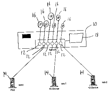
according to an embodiment of the present invention.
FIG. 3 is a diagram of a system of assigning logical addresses
according to a second embodiment of the present invention.
Detailed Description of the Invention
While the invention is susceptible of embodiment in many different
forms, there is shown in the drawings and will herein be described in detail
a preferred embodiment of the invention. It is to be understood that the
present disclosure is to be considered only as an example of the principles of

CA 02362433 2001-08-30
WO 01/50711 PCT/C1S00/33188
-4-
the invention. This disclosure is not intended to limit the broad aspect of
the
invention to the illustrated embodiments. The scope of protection should only
be limited by the accompanying claims.
Referring to Figure 2, there is shown a computer network switch 10
having six ports 12. It should be understood and will be readily apparent to
one of ordinary skill in the art that the network switch could have any number
of ports 12. Connected to three of the ports 12 are network devices 14. The
network devices 14 can be any electrical device capable of communication
over a computer network, such as a personal computer, a programmable logic
controller or an input/output device. The network switch 10 receives a
network message from any one of the network devices 14 and forwards the
network message to an appropriate destination.
The appropriate destination depends on the type of network being
used. For example, in an ethernet network implemented over twisted pair
copper wire, the network switch could be a "smart" network switch and
forward the network message to one or more network devices 14 for which
the network message is intended, or it could be a "dumb" network switch and
forward the message to all network devices 14. In the case of a "dumb"
network switch the network devices 14 for which the network message is not
intended merely ignore the network message. In the case of a token ring type
network, the network switch might merely pass the network message to the
next computer in the ring. All of the scenarios for an appropriate destination
are well known and are readily understood by one of ordinary skill.
The network switch 10 further comprises a logical address server 18
which assigns an IP address 16 to a network device 14 based upon the port
12 of the network switch 10 to which the network device 14 is connected. In
order for the logical address server 18 to know which IP address 16 to assign

CA 02362433 2001-08-30
WO 01/50711 PCT/L1S00/33188
-5-
each port 12, the logical address server 18 must be initially configured by a
networking professional to associate each IP address 16 with each port 12.
In use, when one of the network devices 14 fails, a technician simply
removes the defective network device 14 from the network by disconnecting
it from the port 12. A new network device 14 is then placed on the network
by connecting it to the port 12 from which the failed network device 14 was
disconnected. Either upon connecting the new network device 14 to the
network or upon the network device's 14 request, an IP address 16 is assigned
by the logical address server 18 to the new network device 14 based on the
port 12 of the network switch to which the device is connected. In this
manner, the failed network device 14 and the new network device 14 have the
same IP address 16.
Optionally, the logical address server 18 can be configurable to assign
an IP address 16 based on either the port 12 of the network switch 10 or
assign an IP address 16 based upon a MAC address associated with the
network device 14.
The network switch 10 is preferably connected to network devices 14
by electrical wires and the network messages are preferably electrical
signals.
However, the present invention can be easily adapted to accept fiber optical
cables to connect the network devices to the network switch which transmit
light pulses as the network messages.
While the specific embodiments have been illustrated and described,
numerous modifications come to mind without significantly departing from
the spirit of the invention, and the scope of protection is only limited by
the
scope of the accompanying claims.

Representative Drawing
A single figure which represents the drawing illustrating the invention.
Administrative Status

2024-08-01:As part of the Next Generation Patents (NGP) transition, the Canadian Patents Database (CPD) now contains a more detailed Event History, which replicates the Event Log of our new back-office solution.

Please note that "Inactive:" events refers to events no longer in use in our new back-office solution.

For a clearer understanding of the status of the application/patent presented on this page, the site Disclaimer , as well as the definitions for Patent , Event History , Maintenance Fee  and Payment History  should be consulted.

Event History

Description Date
Inactive: IPC expired 2022-01-01
Inactive: IPC from PCS 2022-01-01
Application Not Reinstated by Deadline 2004-12-07
Time Limit for Reversal Expired 2004-12-07
Deemed Abandoned - Failure to Respond to Maintenance Fee Notice 2003-12-08
Letter Sent 2002-01-14
Inactive: Cover page published 2001-12-18
Inactive: Courtesy letter - Evidence 2001-12-18
Inactive: Notice - National entry - No RFE 2001-12-13
Inactive: First IPC assigned 2001-12-13
Application Received - PCT 2001-12-04
Inactive: Single transfer 2001-11-23
Application Published (Open to Public Inspection) 2001-07-12

Abandonment History

Abandonment Date Reason Reinstatement Date
2003-12-08

Maintenance Fee

The last payment was received on 2002-09-23

Note : If the full payment has not been received on or before the date indicated, a further fee may be required which may be one of the following

  • the reinstatement fee;
  • the late payment fee; or
  • additional fee to reverse deemed expiry.

Please refer to the CIPO Patent Fees web page to see all current fee amounts.

Fee History

Fee Type Anniversary Year Due Date Paid Date
Basic national fee - standard 2001-08-30
Registration of a document 2001-11-23
MF (application, 2nd anniv.) - standard 02 2002-12-09 2002-09-23
Owners on Record

Note: Records showing the ownership history in alphabetical order.

Current Owners on Record
SCHNEIDER AUTOMATION INC.
Past Owners on Record
DENNIS J. W. DUBE
RICHARD A. BAKER
Past Owners that do not appear in the "Owners on Record" listing will appear in other documentation within the application.
Documents

To view selected files, please enter reCAPTCHA code :


To view images, click a link in the Document Description column. To download the documents, select one or more checkboxes in the first column and then click the "Download Selected in PDF format (Zip Archive)" or the "Download Selected as Single PDF" button.

List of published and non-published patent-specific documents on the CPD .

If you have any difficulty accessing content, you can call the Client Service Centre at 1-866-997-1936 or send them an e-mail at CIPO Client Service Centre.


Document
Description 
Date
(yyyy-mm-dd) 
Number of pages   Size of Image (KB) 
Representative drawing 2001-08-30 1 10
Representative drawing 2001-12-17 1 7
Abstract 2001-08-30 1 48
Drawings 2001-08-30 2 24
Claims 2001-08-30 4 94
Description 2001-08-30 5 203
Cover Page 2001-12-18 1 37
Notice of National Entry 2001-12-13 1 195
Courtesy - Certificate of registration (related document(s)) 2002-01-14 1 113
Reminder of maintenance fee due 2002-08-08 1 114
Courtesy - Abandonment Letter (Maintenance Fee) 2004-02-02 1 176
PCT 2001-08-30 2 62
Correspondence 2001-12-13 1 25