Sélection de la langue

Search

Sommaire du brevet 2362433 

Énoncé de désistement de responsabilité concernant l'information provenant de tiers

Une partie des informations de ce site Web a été fournie par des sources externes. Le gouvernement du Canada n'assume aucune responsabilité concernant la précision, l'actualité ou la fiabilité des informations fournies par les sources externes. Les utilisateurs qui désirent employer cette information devraient consulter directement la source des informations. Le contenu fourni par les sources externes n'est pas assujetti aux exigences sur les langues officielles, la protection des renseignements personnels et l'accessibilité.

Disponibilité de l'Abrégé et des Revendications

L'apparition de différences dans le texte et l'image des Revendications et de l'Abrégé dépend du moment auquel le document est publié. Les textes des Revendications et de l'Abrégé sont affichés :

  • lorsque la demande peut être examinée par le public;
  • lorsque le brevet est émis (délivrance).
(12) Demande de brevet: (11) CA 2362433
(54) Titre français: ADRESSAGE DE RESEAU EN FONCTION DU PORT D'UN COMMUTATEUR DE RESEAU
(54) Titre anglais: NETWORK ADDRESSING BASED ON THE PORT OF A NETWORK SWITCH
Statut: Réputée abandonnée et au-delà du délai pour le rétablissement - en attente de la réponse à l’avis de communication rejetée
Données bibliographiques
(51) Classification internationale des brevets (CIB):
  • H04L 12/44 (2006.01)
  • H04L 61/5014 (2022.01)
(72) Inventeurs :
  • BAKER, RICHARD A. (Etats-Unis d'Amérique)
  • DUBE, DENNIS J. W. (Etats-Unis d'Amérique)
(73) Titulaires :
  • SCHNEIDER AUTOMATION INC.
(71) Demandeurs :
  • SCHNEIDER AUTOMATION INC. (Etats-Unis d'Amérique)
(74) Agent: SMART & BIGGAR LP
(74) Co-agent:
(45) Délivré:
(86) Date de dépôt PCT: 2000-12-07
(87) Mise à la disponibilité du public: 2001-07-12
Licence disponible: S.O.
Cédé au domaine public: S.O.
(25) Langue des documents déposés: Anglais

Traité de coopération en matière de brevets (PCT): Oui
(86) Numéro de la demande PCT: PCT/US2000/033188
(87) Numéro de publication internationale PCT: WO 2001050711
(85) Entrée nationale: 2001-08-30

(30) Données de priorité de la demande:
Numéro de la demande Pays / territoire Date
09/476,052 (Etats-Unis d'Amérique) 1999-12-31

Abrégés

Abrégé français

La présente invention porte sur un système d'adressage d'un réseau informatique qui reçoit un message d'un dispositif de réseau et envoie le message réseau vers une destination appropriée. Le commutateur de réseau possède une pluralité de ports de réception et d'envoi de message, ainsi qu'un serveur d'adresse logique qui attribue une adresse logique à un dispositif de réseau en fonction du port du commutateur de réseau auquel est raccordé le dispositif de réseau.


Abrégé anglais


The present invention discloses a network switch for a computer network which
receives a network message from a network device and forwards the network
message to an appropriate destination. The network switch has a plurality of
ports for receiving and forwarding the network message. The network switch has
a logical address server which assigns a logical address to a network device
based upon the port of the network switch to which the network device is
connected.

Revendications

Note : Les revendications sont présentées dans la langue officielle dans laquelle elles ont été soumises.


-6-
CLAIMS
I claim:
1. A network switch for a computer network which receives network
messages from a network device and forwards the signal to an appropriate
destination having a plurality of ports for receiving and forwarding the
network message, the network switch comprising:
a logical address server which assigns a logical address to a network
device based upon the port of the network switch to which the network
device is connected.
2. The network switch of claim 1, wherein the logical address server
assigns the logical address to a network device based upon the port of the
network switch to which the device is connected for less than all of the ports
of the network switch.
3. The network switch of claim 1, wherein the logical address server
assigns the logical address to a network device based upon the port of the
network switch to which the device is connected for a portion of the ports and
assigns a logical address to network devices of other ports based upon the
fixed address of the network device.
4. The network switch of claim 1, wherein the logical address server
is a modified DHCP server.
5. The network switch of claim 1, wherein the logical address server
is a modified BOOTP server.

-7-
6. The network switch of claim 1, wherein the network devices are
connected to the network switch with electrical wires and the network
messages are electrical signals.
7. The network switch of claim 1, wherein the network devices are
connected to the network switch with fiber optic cables and the network
messages are impulses of light.
8. A method of assigning a logical address to network device
connected to a port of a network switch comprising the step of assigning the
logical address based upon the port of the network switch to which the
network device is connected.
9. The method of claim 8, wherein the logical address is assigned
based upon the port of the network switch to which the network device is
connected for less than all of the ports.
10. The method of claim 8, wherein the logical address is assigned
based upon the port of the network switch to which the device is connected
for portion of the ports and comprises the further step of assigning a logical
address to a network device based upon a fixed address of the network device
for a remaining portion of the ports.
11. The method of claim 8, wherein the network devices are
connected to the network switch with electrical wires and the network
messages are electrical signals.

-8-
12. The method of claim 8, wherein the network devices are
connected to the network switch with fiber optic cables and the network
messages are impulses of light.
13. A device for performing the method of claim 8.
14. A method of assigning a logical address to network device
connected to a port of a network switch comprising the steps of attaching the
network device to the network switch; requesting a logical address; and,
assigning the logical address based upon the port of the network switch to
which the network device is connected.
15. The method of claim 14, wherein the logical address is assigned
based upon the port of the network switch to which the device is connected
for less than all of the ports.
16. The method of claim 14, wherein the logical address is assigned
based upon the port of the network switch to which the device is connected
for portion of the ports and comprises the further step of assigning a logical
address to a network device based upon a fixed address of the network device
for a remaining portion of the ports.
17. The method of claim 14, wherein the network devices are
connected to the network switch with electrical wires and the network
messages are electrical signals.
18. The method of claim 14, wherein the network devices are
connected to the network switch with fiber optic cables and the network
messages are impulses of light.

-9-
19. A device for performing the method of claim 14.

Description

Note : Les descriptions sont présentées dans la langue officielle dans laquelle elles ont été soumises.

CA 02362433 2001-08-30
WO 01/50711 PCT/L1S00/33188
NETWORK ADDRESSING BASED
ON THE PORT OF A NETWORK SWITCH
Technical Field
This invention relates to a networking addressing system which
provides logical addresses to network devices based on the port of a network
switch to which the network device is connected.
Background of the Invention
Referring to Figure 1, commonly a Media Access Control (MAC)
address 2 is a fixed address which is given to a network device 4 when it is
manufactured and an Internet Protocol address 6 is a variable address which
is assigned and associated with MAC address 2. In the past, when using an
ethernet network in a factory automation network, users have been plagued
with the problems of managing the relationship of the MAC address 2 with
the Internet Protocol (IP) address 6. Typical addressing systems assign IP
addresses 6 to network devices 4 based on the network device's MAC address
2 without regard to the network device's physical location. Because every
network device 4 has a different MAC address 2, when one network device
4 is unplugged from the network and another network device 4 put in its
place, a subsequently connected network device in the same location as the
first network device 4 will most likely not be assigned the same IP address
6 as the first. This is especially true in systems where IP addresses 6 are
"leased" to a particular MAC address 2 for a particular period of time, such
that even when the network device 4 is not connected to the network, its IP
address 6 remains reserved. This method of assigning IP addresses is
desirable where network devices move from place to place but wish to

CA 02362433 2001-08-30
WO 01/50711 PCT/US00/33188
-2-
maintain their original logical identity on the network or when a particular
location on the network is used by many different network devices at
different times, such as in an office environment.
These addressing systems fall short in a factory automation setting.
Problems occur when a user installs a network device at a fixed location in
a factory with the network device performing a particular function on the
network, such as controlling a machine. If a problem develops with the
network device, maintenance must be performed by a factory technician who
is skilled in the field of repair of the machine but is not skilled in the
area of
networking management. If the network device must be replaced by a
different network device, the machine will not operate until the new MAC
address of the new device is associated with the old IP address (formerly
associated with the removed device's MAC address). This is due to the fact
that the machine (or other device) is configured to communicate with the IP
address. A network management professional must be summoned to perform
the task of associating the IP address with the new MAC address, and, as a
result, the machine must left offline until a networking professional can be
summoned. This loss of machine production time costs a significant loss in
production and, therefore, money. This invention eliminates the need for the
network management professional to be available for replacement of the
network device. The present invention solves this and other problems.
Summary Of The Invention
The present invention discloses a network switch for a computer
network which receives a network message from a network device and
forwards the network message to an appropriate destination. The network
switch has a plurality of ports for receiving and forwarding the network

CA 02362433 2001-08-30
WO 01/50711 PCT/US00/33188
-3-
message. The network switch has a logical address server which assigns a
logical address to a network device based upon the port of the network
switch to which the network device is connected.
In an alternative embodiment, there is disclosed a logical address
server connectable to the port of a network switch. The logical address server
assigns logical addresses to network devices connected to the network switch.
The logical address server assigns a logical address to a network device based
upon the port of the network switch to which the network device is
connected.
Also disclosed is a method of assigning a logical address to network
device connected to a port of a network switch comprising the step of
assigning the logical address based upon the port of the network switch to
which the network device is connected and a device for performing the
method.
Brief Description Of The Dra'VinEs
FIG. 1 is a diagram of a system of assigning logical addresses
according to the prior art.
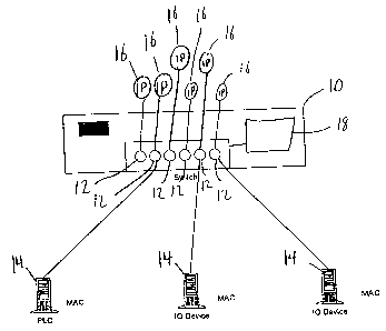
FIG. 2 is a diagram of a system of assigning logical addresses
according to an embodiment of the present invention.
FIG. 3 is a diagram of a system of assigning logical addresses
according to a second embodiment of the present invention.
Detailed Description of the Invention
While the invention is susceptible of embodiment in many different
forms, there is shown in the drawings and will herein be described in detail
a preferred embodiment of the invention. It is to be understood that the
present disclosure is to be considered only as an example of the principles of

CA 02362433 2001-08-30
WO 01/50711 PCT/C1S00/33188
-4-
the invention. This disclosure is not intended to limit the broad aspect of
the
invention to the illustrated embodiments. The scope of protection should only
be limited by the accompanying claims.
Referring to Figure 2, there is shown a computer network switch 10
having six ports 12. It should be understood and will be readily apparent to
one of ordinary skill in the art that the network switch could have any number
of ports 12. Connected to three of the ports 12 are network devices 14. The
network devices 14 can be any electrical device capable of communication
over a computer network, such as a personal computer, a programmable logic
controller or an input/output device. The network switch 10 receives a
network message from any one of the network devices 14 and forwards the
network message to an appropriate destination.
The appropriate destination depends on the type of network being
used. For example, in an ethernet network implemented over twisted pair
copper wire, the network switch could be a "smart" network switch and
forward the network message to one or more network devices 14 for which
the network message is intended, or it could be a "dumb" network switch and
forward the message to all network devices 14. In the case of a "dumb"
network switch the network devices 14 for which the network message is not
intended merely ignore the network message. In the case of a token ring type
network, the network switch might merely pass the network message to the
next computer in the ring. All of the scenarios for an appropriate destination
are well known and are readily understood by one of ordinary skill.
The network switch 10 further comprises a logical address server 18
which assigns an IP address 16 to a network device 14 based upon the port
12 of the network switch 10 to which the network device 14 is connected. In
order for the logical address server 18 to know which IP address 16 to assign

CA 02362433 2001-08-30
WO 01/50711 PCT/L1S00/33188
-5-
each port 12, the logical address server 18 must be initially configured by a
networking professional to associate each IP address 16 with each port 12.
In use, when one of the network devices 14 fails, a technician simply
removes the defective network device 14 from the network by disconnecting
it from the port 12. A new network device 14 is then placed on the network
by connecting it to the port 12 from which the failed network device 14 was
disconnected. Either upon connecting the new network device 14 to the
network or upon the network device's 14 request, an IP address 16 is assigned
by the logical address server 18 to the new network device 14 based on the
port 12 of the network switch to which the device is connected. In this
manner, the failed network device 14 and the new network device 14 have the
same IP address 16.
Optionally, the logical address server 18 can be configurable to assign
an IP address 16 based on either the port 12 of the network switch 10 or
assign an IP address 16 based upon a MAC address associated with the
network device 14.
The network switch 10 is preferably connected to network devices 14
by electrical wires and the network messages are preferably electrical
signals.
However, the present invention can be easily adapted to accept fiber optical
cables to connect the network devices to the network switch which transmit
light pulses as the network messages.
While the specific embodiments have been illustrated and described,
numerous modifications come to mind without significantly departing from
the spirit of the invention, and the scope of protection is only limited by
the
scope of the accompanying claims.

Dessin représentatif
Une figure unique qui représente un dessin illustrant l'invention.
États administratifs

2024-08-01 : Dans le cadre de la transition vers les Brevets de nouvelle génération (BNG), la base de données sur les brevets canadiens (BDBC) contient désormais un Historique d'événement plus détaillé, qui reproduit le Journal des événements de notre nouvelle solution interne.

Veuillez noter que les événements débutant par « Inactive : » se réfèrent à des événements qui ne sont plus utilisés dans notre nouvelle solution interne.

Pour une meilleure compréhension de l'état de la demande ou brevet qui figure sur cette page, la rubrique Mise en garde , et les descriptions de Brevet , Historique d'événement , Taxes périodiques et Historique des paiements devraient être consultées.

Historique d'événement

Description Date
Inactive : CIB expirée 2022-01-01
Inactive : CIB du SCB 2022-01-01
Demande non rétablie avant l'échéance 2004-12-07
Le délai pour l'annulation est expiré 2004-12-07
Réputée abandonnée - omission de répondre à un avis sur les taxes pour le maintien en état 2003-12-08
Lettre envoyée 2002-01-14
Inactive : Page couverture publiée 2001-12-18
Inactive : Lettre de courtoisie - Preuve 2001-12-18
Inactive : Notice - Entrée phase nat. - Pas de RE 2001-12-13
Inactive : CIB en 1re position 2001-12-13
Demande reçue - PCT 2001-12-04
Inactive : Transfert individuel 2001-11-23
Demande publiée (accessible au public) 2001-07-12

Historique d'abandonnement

Date d'abandonnement Raison Date de rétablissement
2003-12-08

Taxes périodiques

Le dernier paiement a été reçu le 2002-09-23

Avis : Si le paiement en totalité n'a pas été reçu au plus tard à la date indiquée, une taxe supplémentaire peut être imposée, soit une des taxes suivantes :

  • taxe de rétablissement ;
  • taxe pour paiement en souffrance ; ou
  • taxe additionnelle pour le renversement d'une péremption réputée.

Veuillez vous référer à la page web des taxes sur les brevets de l'OPIC pour voir tous les montants actuels des taxes.

Historique des taxes

Type de taxes Anniversaire Échéance Date payée
Taxe nationale de base - générale 2001-08-30
Enregistrement d'un document 2001-11-23
TM (demande, 2e anniv.) - générale 02 2002-12-09 2002-09-23
Titulaires au dossier

Les titulaires actuels et antérieures au dossier sont affichés en ordre alphabétique.

Titulaires actuels au dossier
SCHNEIDER AUTOMATION INC.
Titulaires antérieures au dossier
DENNIS J. W. DUBE
RICHARD A. BAKER
Les propriétaires antérieurs qui ne figurent pas dans la liste des « Propriétaires au dossier » apparaîtront dans d'autres documents au dossier.
Documents

Pour visionner les fichiers sélectionnés, entrer le code reCAPTCHA :


Pour visualiser une image, cliquer sur un lien dans la colonne description du document. Pour télécharger l'image (les images), cliquer l'une ou plusieurs cases à cocher dans la première colonne et ensuite cliquer sur le bouton "Télécharger sélection en format PDF (archive Zip)" ou le bouton "Télécharger sélection (en un fichier PDF fusionné)".

Liste des documents de brevet publiés et non publiés sur la BDBC .

Si vous avez des difficultés à accéder au contenu, veuillez communiquer avec le Centre de services à la clientèle au 1-866-997-1936, ou envoyer un courriel au Centre de service à la clientèle de l'OPIC.


Description du
Document 
Date
(aaaa-mm-jj) 
Nombre de pages   Taille de l'image (Ko) 
Dessin représentatif 2001-08-30 1 10
Dessin représentatif 2001-12-17 1 7
Abrégé 2001-08-30 1 48
Dessins 2001-08-30 2 24
Revendications 2001-08-30 4 94
Description 2001-08-30 5 203
Page couverture 2001-12-18 1 37
Avis d'entree dans la phase nationale 2001-12-13 1 195
Courtoisie - Certificat d'enregistrement (document(s) connexe(s)) 2002-01-14 1 113
Rappel de taxe de maintien due 2002-08-08 1 114
Courtoisie - Lettre d'abandon (taxe de maintien en état) 2004-02-02 1 176
PCT 2001-08-30 2 62
Correspondance 2001-12-13 1 25