Note: Descriptions are shown in the official language in which they were submitted.
CA 02362659 2001-12-12
WO 00/46502 PCT/US00/03195
TITLE: COALESCING DEVICE AND METHOD FOR
REMOVING PARTICLES FROM A ROTARY GAS
COMPRESSOR
SPECIFICATION
The present invention relates to the use of a rotary compressor system, an oil
separator
for use with a rotary compressor system and a method for separating oil in a
rotary
compressor system which is reusable and continuously operable system and
utilizes a series
of coalescing devices to eliminate liquid particles from a gas stream
utilizing a rotary screw
compressor.
BACKGROUND OF THE INVENTION
The present invention generally relates to compressor systems and, more
particularly,
to oil flooded, rotary screw gas compressor systems having lube-oil
circulation systems and
apparatus. The present invention relates to a method for enhancing the
production from those
systems by txtilizing a reliable, non-disposable coalescing system to enlarge
and entrain liquid
particles in a multi-step process yielding a cleaner, liquid free stream than
currently available
methods.
Helical lobe rotary compressors, or "screw compressors," are well-known in the
air
compressor refrigeration and natural gas processing industries. This type of
gas compressor
generally includes two cylindrical rotors mounted on separate shafts inside a
hollow, double-
barreled casing. The side walls of the compressor casing typically form two
parallel,
overlapping cylinders which house the rotors side-by-side, with their shafts
parallel to the
_.. . __.~...-..- _..
_ _ w _ _.,,.,..,...,..,.. _... .. . .
CA 02362659 2001-12-12
WO 00/46502 PCT/US00/03195
ground. As the name implies, screw compressor rotors have helically extending
lobes and
grooves on their outer surfaces. During operation, the lobes on one rotor mesh
with the
corresponding grooves on the other rotor to form a series of chevron-shaped
gaps between the
rotors. These gaps form a continuous compression chamber that communicates
with the
compressor inlet opening, or "port," at one end of the casing and continuously
reduces in
volume as the rotors turn and compress the gas toward a discharge port at the
opposite end of
the casing. The compressor inlet is sometimes also referred to as the
"suction" or "low
pressure side" while the discharge is referred to as the "outlet" or "high
pressure side."
Screw compressor rotors intermesh with one another and rotate in opposite
directions
in synchronization within a housing. The impellers operate to sweep a gas
through the
housing from an intake manifold at one end of the housing to an output
manifold at the other
end of the housing. Commercially available compressors most commonly include
impellers
or rotors having four lobes, however, others have been designed to have five
or more lobes,
however, it may be possible to use a rotor or impeller which has only 2-5
lobes. The present
invention relates to a system used in conjunction with this type of rotors.
The rotor shafts are typically supported at the end walls of the casing by
lubricated
bearings and/or seals that receive a constant supply of lubricant from a
lubricant circulation
system. Since the lubricant is typically some type of oil-based liquid
compound, this part of
the compressor system is often referred to simply as the "lube-oil" system.
However, the
terms "lubricant," "lube-oil," and "oil" encompass a wide variety of other
compounds that
may contain other materials besides oil, such as water, refrigerant, conosion
inhibitor, silicon,
Teflon , and others. In fact, the name "lube-oil" helps to distinguish this
part of the
compressor system from other components that may use similar types of oil-
based fluids for
other purposes, such as for power transmission in the hydraulic system or
insulation in the
2
CA 02362659 2001-12-12
WO 00/46502 PCT/US00/03195
electrical system.
Like the lube-oil circulation system in many automobiles, compressor lube-oil
systems generally include a collection reservoir, motor-driven pump, filter,
and pressure
and/or temperature sensors. Since many lubricants degrade at high temperature
by losing
"viscosity," lube-oil systems for high temperature applications, such as screw
compressors,
generally also include a cooler for reducing the temperature of the lubricant
before it is
recirculated to the seals and bearings. So-called "oil flooded" rotary screw
compressors
further include means for recirculating lubricant through the inside of the
compressor casing.
Such "lube-oil injection" directly into the gas stream has been found to help
cool and
lubricate the rotors, block gas leakage paths between or around the rotors,
inhibit corrosion,
and minimize the level of noise produced by screw compressors.
A typical oil flooded screw compressor discharges a high-pressure and high-
temperature stream consisting of a mixture of gas and oil. The oil and any
related liquid must
be separated from the high pressure gas. The present invention relates to a
technique for
coalescing the liquid and oil particles by multi-step process, wherein the
first step re-entrains
the particles using a first vane pack and a flow at high velocity, and then a
second step passes
the particles and gas through a second vane pack, thereby removing essentially
all of the
liquid and oil particles, creating an essentially liquid and oil free gas
stream.
At least two, but optionally, a plurality of vane packs can be used in
sequence in the
present invention to achieve the desired clean stream effect. The vane packs,
which are the
coalescing means or "coalescer means", are connected to each other in series
and connected
based on a defined size relation. In particular, the first vane pack is
smaller in surface area
than the second vane pack. After leaving the vane packs, which are also be
called chevron
shaped mist eliminators, the gas stream is cooled, filtered, and recirculated
to the compressor
3
.~ ... ..__......
_......._._., ._.~...._....
. .. .w_..~.....~..~.,.,... _,... ..... .
~..._..,,..,_
CA 02362659 2001-12-12
WO 00/46502 PCT/US00/03195
bearings and main oil injection port.
There are a variety of patents which generally relate to screw compressors and
compressors in general, such as US. Patent 5,439,358, 2,489,997 and 3,351,227
but none
discloses the multi-pack filtering concept using vane packs as described in
the present
invention. Related patents which discuss compressor features, but not the
multi-vane pack
system of the invention include 5,564,910, 5,490,771, 5,405,253, 4,758,138,
5,374,172,
4,553,906, 5,090,879, 4,708,598, and 5,503,540.
SUMMARY OF THE INVENTION
The screw compressor has a first inlet port for receiving a low pressure gas
stream, a
main lubrication injection port for receiving a first lubrication stream, an
inlet bearing
lubrication port for receiving a second lubrication stream, a discharge
bearing and seal
lubrication port for receiving a third lubrication stream, a prime mover for
powering screw
compressor and a discharge port for discharging a high pressure compressed gas
mixture from
the compressor. The compressor system may also include a suction scrubber for
removing
liquids from the gas before it is supplied to the compressor.
A separator receives the compressed gas mixture and coalesces the liquid
particles in
at least a two step process, wherein the compressed mixture is passed through
at least two
coalescing means connected in series to remove liquid particles, and wherein
the first
coalescing means is smaller in surface area than the second coalescing means.
The separator
then discharges a high pressure stream (preferably having a viscosity
consistent with
manufacturer's specifications for the operation of the rotary screw
compressor) and a high
pressure gas stream.
4
,...,_..,. ...~......_.. _... _..~,..~...,~,.....,..._ _ ... .._.. .. _
...,,.,........,~..~...._..m-.,~..~._-..,..,,~._ .
_._....~.~....._,~~....,.~.~.._._ _......~..~...._.__.
CA 02362659 2001-12-12
WO 00/46502 PCT/[3S00/03195
In one embodiment, the high pressure lubricant stream preferably has a
viscosity of at least 4
centistokes.
A splitter divides the high pressure lubrication stream into a first flow or
branch and a
second flow or branch. The first flow is received by a cooler for creating a
cooled first flow
while the second flow is received and mixed with the cooled first flow by a
thennostat to
create a mixed flow. A filter assembly receives and filters the mixed flow and
creates a
filtered flow. The filter assembly may include at least one liquid filter
and/or an gas pressure
gauge and an outlet pressure gauge for enabling monitoring of the pressure of
the mixed flow
into the filter assembly and the filtered flow out of the filter assembly.
FIGURES
The above and other objects, features and other advantages of the present
invention
will be more clearly understood from the following detailed description taken
in conjunction
with the accompanying drawings, in which:
Figure 1 is a diagram of the compressor system utilizing the novel coalescing
means
of the present invention.
Figure 2 is a diagram of the separator 26 with the unique coalescing means of
the
present invention.
DETAILED DESCRIPTION
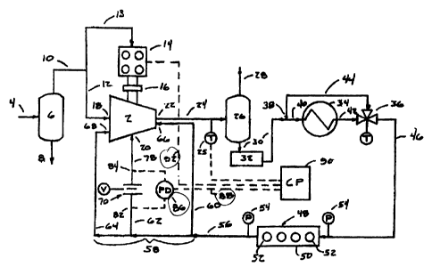
FIGURE 1 shows a diagram of a gas compression process and compressor system
including a rotary screw gas compressor 2. The compressor 2 is preferably a
Model TDSH
(163 through 355) rotary screw compressor available from Frick Company in
Waynesboro,
Pennsylvania. However, a variety of other oil flooded rotary screw compressors
may also be
used.
In FIGURE 1, a raw gas feed stream 4 from a natural gas well (not shown), or
other
5
_.~_.~..................a....._. _ _....,~.,.~w...,~.,~.~~._w..... _. .
_,_...._~~__ _
CA 02362659 2001-12-12
WO 00/46502 PCT/US00/03195
gaseous fluid source, is supplied to a scrubber 6 for separating fluids and
any entrained solids
from the raw gas stream 4. The scrubber 6 may be any suitable two- or three-
phase separator
which discharges a liquid stream 8 to a disposal reservoir (not shown) and an
essentially dry
low pressure gas stream 10 to the compressor 2. The gas may also be dried
using other well-
known conventional processes. The dry low pressure gas stream 10 is then
supplied to an gas
stream 12 and may also be supplied to a fuel stream 13 for fueling a prime
mover 14.
Although the prime mover 14 shown in FIG. 1 is a natural gas engine, a variety
of other
power plants, such as diesel engines or electric motors, may also be used to
drive the
compressor 2 through a coupling 16.
The compressor 2 receives low pressure gas through an inlet port 18. A
suitable
lubricant, is supplied to the inside of the casing of the compressor 2 through
a main oil
injection port 20 where it is mixed with the gas to form a low pressure
gas/oil mixture. The
low pressure gas/oil mixture is then compressed and discharged from the
compressor 2
through a discharge port 22 into a high pressure gas/oil mixture stream 24.
The discharge
temperature of the gas/oil mixture from compressor 2 may be monitored by a
temperature
sensor 25.
FIGURE 2 shows in detail the separator 26 which receives the high pressure
gas/oil
mixture stream 24 and first coalesces the liquid particles in a first
coalescing means 100,
which is also conventionally known in the business as a "vane pack." This is
the first of at
least two vane packs which can be used in series to coalesce liquid in this
system. The high
pressure gas/oil mixture stream 24 is passed through a first vane pack 100, at
a velocity so
that the liquid particles are re-entrained along the sides of the first vane
pack 100, causing the
particles to enlarge from a size of up to about 1 micron to a size of about 25
microns, or even
larger such as over 35 microns. The re-entrained particles are then passed in
the high pressure
6
.n...M,M,.~,.,..M.-,,..._..-.,..-,.~,,.....,.,~.,. . _. , ..~~..,~__. .
_.___..._.~..~.,- __...__ .
CA 02362659 2001-12-12
WO 00/46502 PCT/IJS00/03195
gas/oil mixture to a second coalescing means, which is another vane pack,
hereafter termed
"the second vane pack" 102. The second vane pack, 102, has a surface area
which is larger
than the first vane pack 100. In a preferred embodiment, it is expected that
the second vane
pack would be at least 50% larger in surface area than the first vane pack. In
the most
preferred embodiment, the second vane pack 102 would be 4 times the surface
area of the
first vane pack 100.
The treated high pressure gas/oil mixture can be optionally passed through
additional
coalescing vane packs. Probably no more than 10 additional vane packs would be
used in
any one compressor to clean the stream of particles. However, there could be
no limit, other
than commercial practicality to the number of vane packs used to remove liquid
particles and
create an essentially liquid free gas phase. An essentially liquid free gas
phase would
typically maintain a liquid content in the gas stream at less than
approximately 25 ppm. The
additional coalescing means are shown as 104, the number 104 is intended to
represent one or
more of these coalescing means which can be porous filters.
As an alternative embodiment, inside the separator, a second mesh pad 106 can
be
used. Also it should be noted that a mesh pad can be used instead of the
second vane pack. In
another embodiment, a mesh pad could be used as a third or fourth vane pack,
after using
two vane packs identical to vane pack 100. The mesh pad is preferably a
knitted wire mesh
pad. The wire of the mesh pad can be made out of different materials, and can
be, for
example, steel wool. Optionally, the vane packs can be co-knit fibers which
are impervious
or highly resistant to the corrosiveness of the natural gas stream high
pressures and high
temperatures. Usable vane packs of the present invention can include fiber bed
vane packs.
The knitted wire mesh pads and parallel vane units are the most common methods
of
removing entrained liquid droplets from gas streams in industrial processes.
These are known
7
....,...,,,....._..___ _.._ _._.~,._._. ._.....__~_....,,......_~.._....
,_.__.._w~.....
CA 02362659 2001-12-12
WO 00/46502 PCTIUSOO/03195
as mist eliminators or sometimes "chevron mist" eliminators. The mesh pad is
designed for a
certain kind of thickness for the mesh, such as a 6 or 8 inch thick pad,
however, other styles,
and windings may be used.
The vane packs normally come in 8 inch thick pads, but are also available in
other
sizes, such as 6 inch sizes or smaller or even larger. There are several
different types of vane
packs. Vane packs can have hooks to trap liquids, they can have different
angles for flowing
the gas stream. Some vane packs are known as chevron shaped mist eliminators.
Vane packs
usable in the present invention can be purchased from ACS Industries, LP of
14211 Industry
Road, Houston, Texas 77053 and the most usable ones sold by this company are
known as
"Plate-Pak" units, with the term "Plate-Pak" being a trademark of ACS
Industries. One, two,
three, four or move vane packs can be used in series and be within the scope
of the
contemplated invention.
The vessel diameter of the separator 26, has to be carefully selected, so that
the liquid
particles which have been coalesced and foirned in the vane packs can drip off
of the vane
packs, unimpeded by the upward high pressure gas flow rate, and then fall to
the bottom of
the separator vesse126.
Returning to Figure 1, the separator 26 discharges a high pressure gas stream
28 for
further processing and/or distribution to customers. In addition, the
separator also discharges
a high temperature oil stream 30 to a lube-oil cooler 34, which can be, in
some cases, a lube-
oil collection reservoir 32 via one- to three- inch diameter stainless steel
tubing, or other
suitable conduits. Alternatively, the lube-oil may simply collect at the
bottom of the
separator 26. The lube-oil cooler 34 preferably cools the high temperature
lube-oil stream 30
from a temperature in the range of 190 F to 220 F, or preferably 195 F to 215
F, to a
temperature in the range of 120 F to 200 F, and preferably in the range of 140
F to 180 F, or
8
___ ._ ._.._.~.~.....,_.._._..._.,_,. ___....._..,.._,._......,.__....
_.._~..~_...... .
CA 02362659 2007-06-11
nearly 170'F for an oil flow rate of about 10- 75.gallons per minute.
Typical coolers that may be used with the disclosed compressor system include
shell
and tube coolers such as ITT Standard Model No. SX 2000 and distributor
Thermal
Engineering Company's (of Tulsa, Oklahoma) Model Nos. 05060, 05072, and
others. Plate
and frame coolers, such as Alfa Laval MGFG Models (with 24 plates) and M I
OMFG Models
(with 24 or 38 plates) may also be used, as may forced air "fin-fan" coolers
such as Model
L156S available from Cooler Service Co., Inc. of Tulsa, Oklahoma. A variety of
other heat
exchangers and other cooling means are also suitable for use with the
compressor system
shown.
In a preferred embodiment, the temperature of the lubricant leaving the lube-
oil cooler
34 is controlled using a by-pass slream 44 and a thermostatic valve 36 which
is preferably a three- way
thermostatic valve such as Model No. 20 10 available from Fluid Power
Engineering Inc.
of Waukesha, Wisconsin. Although the manufacturer's specifications for this
particular type
of valve show it as having one inlet port and two outlet ports, it may
nonetheless be used
with the present system by using one of the valve's outlet ports as an inlet
port. Other lube-oil
temperature control systems besides thermostats and/or thermostatic control
valve
arrangements may also be used.
In the present invention, the oil pressure to the bearings must be maintained
at a
suitably high pressure, preferably higher than the pressure of the gas supply
to the compressor
in order to prevent the gas from invading the bearings. To provide a margin of
safety, oil
from the bearings is allowed to drain to position inside the casing near a
pressurized "closed
thread" on the rotors. A closed thread is a position on the rotors which is
isolated from both
the suction and discharge lines, and therefore contains gas at a pressure
between the suction
and discharge pressures. The closed thread is preferably at a position along
the length of the
9
CA 02362659 2007-06-11
rotors where the pressure is about one and a half times the absolute suction
pressure of the
compressor at full capacity. Consequently, the pressure of the oil leaving the
bearings is
maintained at roughly one and a half times the absolute pressure of the
compressor inlet.
As shown in FIGURE 1, the high temperature oil stream 30 is split into two
branches
(or "flows") by a two-way splitter 38 prior to reaching the thermostat 36. The
splitter 38 is
preferably formed from T-shaped stainless steel tubing; however, other "T"
fittings may also
be used. The first branch 40 of high temperature lube-oil stream 30 goes
directly into the
cooler 34 where it is discharged through a cooled lube-oil branch 42 into the
thermostatic
valve 36 which has two inlets and one outlet. The second, or "by-pass," branch
of high
temperature lube-oil stream 30 bypasses the cooler 34 and goes directly into
the thermostatic
valve 36 where it may be mixed with lubricant from the cooled lube-oil branch
42 to control
the temperature of a mixed (first and second branch) cooled lube-oil stream 46
leaving the
thermostatic valve 36. By controlling the amount of lube-oil from each of the
first and
second branches or "flows" 42 and 44 flowing through the thermostatic valve
36, the
thermostatic valve 36 can control the temperature of the cooled lube-oil
stream 461eaving the
thermostatic valve 36.
The cooled lube-oil stream 46 then flows through a filter assembly 48 to
create a
filtered lubricant stream 56. The filter assembly 48 includes a housing 50 for
supporting a
plurality of filters 52. A preferred filter housing 50 is available from
Beeline of Odessa,
Texas, for supporting four filters 52, such as Model Nos. B99, B99 MPG, and
B99HPG
available from Baldwin Filters of Kearney, Nebraska. However, a variety of
other filters and
filter housings may also be used. Pressure indicating sensors 54 may also be
provided at the
inlet and outlet of the filter housing 50 for determining the pressure drop
across the filters 52
and providing an indication as to when the filters need to be changed. The
filter assembly 48 may also be
CA 02362659 2007-06-11
arranged in other parts of the process, such as between the reservoir 32 and
two-way splitter
38.
Optionally, the present invention may include a mechanism whereby downstream
of
the filter assembly 48, the filtered lubricant stream 56 flows into a three-
way splitter 58
forming a discharge bearing and an outlet bearing branch 60, an orifice branch
62, and a inlet
bearing branch 64. The outlet bearing branch 60 provides filtered and cooled
lube-oil to the
seals and discharge bearings of the compressor 2 through a lubrication port 66
while the inlet
bearing branch 64 provides filtered and cooled lube-oil to the inlet bearings,
and possibly a
balance piston, through lubrication port 68. The orifice brand 62 provides
filtered and cool
lube-oil to the main oil injection port 20 through an optional valve 70.
The present invention relates to the use of a plurality of vane packs, at
least two,
which are termed coalescing means in this patent. A first vane pack is
preferably used at a
flow through rate beyond the stated limitations of the vane pack, which then
would cause
particles to grow in size yet stay in the gas phase. The first vane pack
effectively causes the
particles to be re- entrained and grow larger, while passing at a high
velocity while still in the
gas phase to a second vane pack. One of the novel features of the present
invention relates to
the size of the vane packs. In the most preferred embodiment, the size of the
first vane pack
is smaller in surface area than the second vane pack in a ratio of 4: 1, and
the two vane packs
are connected in series.
The second vane pack would preferably operate at or less than the stated vane
pack
limits. In the preferred embodiment, not only would the second vane pack be
larger in
surface area than the first vane pack but it also should be capable of
effectively coalescing all
the particles from the first vane pack into particle sizes large enough for
gravity to effect
separation of the particles from the gas phase. This multiple vane pack
configuration enables
a wide range of particles to become entrained in the second vane pack and then
possibly
11
CA 02362659 2001-12-12
WO 00/46502 PCT/USOO/03195
eliminate the need for disposable coalescing filters.
It is particularly notable that a separator with more than one vane pack, as
suggested
in the present invention, will now operates at very low velocities as well as
high velocities,
effectively broadening the range of the separator and the overall compressor
system.
In an alternative embodiment, it is possible to have the vane packs in a
configuration
in the separator where the small vane pack is after the larger vane pack.
While the advantages
of the re-entrainment of the particle would be lost, the two pack system would
still yield the
increased capacity, and range of the separator.
It is also important to note that at low velocities of gas flow through, that
the
combination of the two vane packs work much better and more effectively than
one vane
pack, increasing the range of the compressor.
It is believed that the compressor of the present invention will find utility
in a wide
variety of applications, particularly where sustained pumping operation is
desired. These
improved compressors may be usable in the natural gas and oil business, and
also for water
pumping systems, food processing systems, and possibly freeze drying systems
which utilize
compressors.
The above described description and the drawing shown are only an example of
what
is contemplated to be within the scope of the invention. It is to be
understood that the
invention is not limited to the precise embodiments described above and that
various changes
and modifications may be effected therein by one skilled in the art without
departing from the
spirit of the invention as defined.
12
_ . ._._.__ ..._._..._~ a... _,_._...._... ~_,.~..~..__....ry.. .. .._ _. __.