Note: Descriptions are shown in the official language in which they were submitted.
CA 02362762 2001-08-23
WO 00/51480 PCT/US00/05295
1
METHOD AND APPARATUS FOR BREWING A FLUID EXTRACT USING AN
INCLINED FILTER POUCH CONTAINING FLAVOR EXTRACTABLE PARTICLES
10 FIELD OF THE INVENTION
The present invention relates to brewing beverages and more particularly to a
method of
and apparatus for brewing beverages in filter pouches. Even more particularly,
the present
invention relates to a method and apparatus for reducing brew water bypass of
filter pouches and
improving consistency of brewing within filter pouches.
BACKGROUND OF THE INVENTION
Brewing coffee typically results in the extraction of 15% to 30% yield of
dissolved solids
from coffee particles, which are mixed with hot brew water for several
minutes. A resulting fluid
extract is gravity filtered from spent coffee grounds by a piece of filter
paper. Commercial
brewing machines provide about half a gallon of hot water, typically at about
195°F to a spray
nozzle above a brew basket. In the brew basket is placed an open cup-shaped
filter onto which is
placed a quantity of flavor extractable coffee particles. When brew water is
sprayed onto the
loosely packed particles, the particles tend to float and many become
suspended or fluidized in
the brew water. This is believed to represent the ideal condition for brewing
the maximum
dissolved solids from the particles. Brew water is typically sprayed for about
3 minutes onto the
particles where it continuously flushes extracted material from the particles
as the fluid extract
passes through the filter. The brew basket preferably has a discharge opening
under the filter
sufficient to drain all fluid extract from the filter in about 3 to 4 minutes.
A problem with the standard loose particle brewing system is that particle
spillage and
contamination are present at different points in the process. For example,
particles may be spilled
when manually dumping them into the cup-shaped filter. Also, particles may
bypass the filter if
brew water overflows the filter or the filter is otherwise placed improperly
in the brew basket.
Furthermore, each batch of spent grounds has to be removed and is often
spilled when the wet
filter is pulled from the brew basket for disposal. To solve the particle
containment problem, the
CA 02362762 2001-08-23
WO 00/51480 PCT1US00/05295
2
commercial brewing industry has adopted filter pouches of various designs,
wherein a
pre-measured quantity of loosely packed particles is totally enclosed within
each pouch. The user
therefore never handles particles directly.
Although filter pouches may solve one problem, they often cause other
problems. For
example, even though particles may be loosely packed within a filter pouch,
insufficient space for
particles to expand and become fluidized can result in the agglomeration of
some particles. The
agglomerated condition is much less conducive to extraction than is particle
suspension. Lower
percentages of dissolved solids are extracted when pouches have insufficient
internal space. Prior
art discloses pouches of complex and expensive construction which provide for
pouch expansion
in order to provide the required internal space.
Another pouch problem is that filter material located between the brew water
spray and
the pouch-contained particles may interfere with the fluidizing of particles.
The brew water must
first enter the pouch before particles may be fluidized for brewing. Although
brew water easily
passes through filter material, overall open area is often insufficient to
allow the full flow of brew
water into the pouch. If the pouch is not able to adopt a cup-shape to form a
reservoir, some brew
water may bypass the filter pouch, ultimately diluting the fluid extract from
the pouch. Other
pouch and brew basket designs intend for the pouch to form a fluid seal with
the basket so that
external bypass cannot occur. Such sealing is inconsistent, however.
Furthermore, when a filter
pouch is partially filled with particles in order to permit particle
expansion, manual handling of
the pouch may result in most of the particles accumulating at one end of the
pouch. If this is not
corrected when the pouch is manually laid horizontally in the brew basket, a
portion of the pouch
will likely be empty. Brew water easily finds such empty portions and flows
directly through the
pouch without contacting particles. This too is an undesirable form of brew
water bypass.
What is needed is a filter pouch brewing system which reduces undesirable brew
water
bypass and yet provides sufficient space for particles to become suspended in
brew water inside
the pouch for consistently optimum brewing.
SUMMARY OF THE INVENTION
In practicing the present invention the problems of particle containment, brew
water
bypass, and providing space within the pouch for particles to expand without
agglomerating are
solved, so that consistent and optimum brewing is possible with each
replacement filter pouch
used in a brewing system.
In one preferred embodiment of the present invention, a method of brewing a
fluid
extract uses a filter pouch containing flavor extractable particles. The
method includes a step of
CA 02362762 2001-08-23
WO 00/51480 PCT/US00/05295
3
supporting a fully compliant, fluid-permeable filter pouch partially filled
with flavor extractable
particles such that the pouch is inclined at an angle to horizontal ranging
from about 30° to about
90° so that the particles accumulate at a bottom end of the filter
pouch. Another step is directing
brew water to near an upper end of the filter pouch above the particles. The
brew water enters the
S filter pouch without the need for an opening in the filter pouch. The brew
water drops to infiltrate
the particles.
The particles are partially fluidized by and suspended in the brew water and
they rise
with the brew water into an empty portion of the filter pouch without a need
for opposing sides of
the filter pouch to separate to generate internal space. A further step
includes brewing a fluid
extract from the particles in the filter pouch and discharging the fluid
extract from the filter
pouch. The filter pouch has sufficient exit area that a fluid extract
discharge rate matches a rate of
brew water entry into the filter pouch when a fluid head is produced inside
the filter pouch which
is at least as great as a vertical depth of particles in the filter pouch.
The filter pouch is preferably supported in a brew basket by a fluid-permeable
support
member. The method further comprises the step of draining the fluid extract
from the brew basket
at a rate sufficient to prevent a pool of fluid extract contacting the bottom
end of the filter pouch
so that the fluid extract discharge rate remains substantially undisturbed.
The step of directing brew water to near an upper end of the filter pouch is
preferably
accomplished by using a brew water conduit in contact with an outer surface of
the filter pouch to
reduce surface tension thereat as brew water flows over or through the
conduit, such that the
brew water enters the filter pouch with minimal resistance, thereby reducing
brew water running
off the outer surface of the filter pouch. The brew water conduit is
preferably a plurality of
flexible fingers in fluid communication with a brew water reservoir having
drain holes. The
flexible fingers contact the outer surface of the filter pouch as brew water
flows over the fingers
from the drain holes.
In another preferred embodiment of the present invention, a replaceable filter
pouch and
reusable brew basket apparatus for a brewing system includes a fully
compliant, fluid-permeable
filter pouch. The filter pouch is partially filled with flavor extractable
particles. Also included is a
brew basket having a fluid-permeable support member therein. The support
member supporting
the filter pouch is at an angle to horizontal ranging from about 30° to
about 60°. The support
member locates a bottom end of the filter pouch sufficiently above a bottom
surface of the brew
basket to avoid contact with a fluid extract pool at the bottom of the brew
basket during brewing.
Further included is a means for directing hot brew water from a reservoir to
near an upper end of
the filter pouch for entry into the filter pouch above a level of particles
therein, so that brew
CA 02362762 2001-08-23
WO 00/51480 PCT/US00/05295
4
water infiltrates the particles to brew a fluid extract therefrom. The fluid
extract drains from the
filter pouch into the bottom of the brew basket having an orifice therein such
that the fluid extract
discharges to a removable container therebelow.
The reservoir is preferably connected to the brew basket for receiving brew
water from a
spray head of a brewing machine. The reservoir has a plurality of drain holes
at a bottom end of
the reservoir. The drain holes are located adjacent to flexible fingers
extending from the bottom
end and contacting an outer surface of the filter pouch to reduce surface
tension at the outer
surface. The brew water, flowing from the reservoir through the drain holes
and over the flexible
fingers to the outer surface of the filter pouch, flows primarily into the
filter pouch instead of
running off the outer surface.
The filter pouch when inclined has the particles accumulate at a bottom end of
the filter
pouch such that the brew water entering the filter pouch drops onto and
infiltrates the particles.
The particles are partially fluidized by and suspended in the brew water and
they rise with the
brew water into an empty portion of the filter pouch preferably without a need
for opposing sides
of the filter pouch to separate to generate internal space.
Preferably, the filter pouch when inclined provides sufficient exit area that
a fluid extract
discharge rate matches a rate of brew water entry into the filter pouch when a
fluid head is
produced inside the filter pouch which is at least as great as a vertical
depth of particles in the
filter pouch.
BRIEF DESCRIPTION OF THE DRAWINGS
While the specification concludes with claims which particularly point out and
distinctly
claim the present invention, it is believed that the present invention will be
better understood
from the following description of preferred embodiments, taken in conjunction
with the
accompanying drawings, in which like reference numerals identify identical
elements and
wherein:
FIG. 1 is a front elevation view of a preferred embodiment of the filter pouch
of the
present invention, disclosing a partially filled rectangular pouch sealed
around its perimeter by a
fin seal;
FIG. 2 is a side elevation view thereof, showing a substantially flat pouch;
FIG. 3 is a plan view of a preferred embodiment of the brew basket of the
present
invention, showing a handle, a brew water reservoir, and a fluid permeable
support member made
of perforated metal;
CA 02362762 2001-08-23
WO 00/51480 PCT/US00/05295
FIG. 4 is a front elevation cross-section view thereof, taken along section
line 4-4 of FIG.
3, showing flexible fingers extending from the reservoir;
FIG. 5 is a front elevation cross-section view similar to FIG 4, showing the
preferred
filter pouch of the present invention being placed onto the support member of
the brew basket of
5 the present invention;
FIG. 6 is a front elevation cross-section view similar to FIG 4, showing the
preferred
filter pouch of the present invention fully inserted into the brew basket of
the present invention,
with the flexible fingers in contact with an outer surface of the filter pouch
near the upper end of
the filter pouch;
FIG. 7 is a front elevation cross-section view similar to FIG 4, showing the
preferred
filter pouch of the present invention being initially filled with brew water
from the reservoir via
the drain holes and flexible fingers;
FIG. 8 is a front elevation cross-section view similar to FIG 4, showing the
preferred
filter pouch of the present invention discharging fluid extract while
particles have expanded and
risen in the filter pouch; and
FIG. 9 is a front elevation cross-section view similar to FIG 4, showing the
preferred
filter pouch of the present invention after brewing has ceased with the filter
being removed from
the brew basket for disposal.
DETAILED DESCRIPTION OF THE INVENTION
Refernng now to the drawings, and more particularly to FIGS. 1 and 2, there is
shown a
first preferred embodiment of the filter pouch of the present invention,
generally indicated as 10.
Filter pouch 10 is preferably rectangular in shape and has fm seals 12 around
its perimeter. Filter
pouch 10 is preferably made uniformly front and back of porous heat-sealable
filter paper, such
as #3968, a fluid permeable filter paper available from Dexter Corporation of
Windsor Locks,
Connecticut. Filter pouch 10 is preferably made at low cost by high speed
machinery, such as by
form-n-fill-seal machines. The manufacture of pouch 10 is well known in the
art. Two parallel
continuous webs or one web folded of filter material are fed together at a
point where fin seals
are made via heat and pressure bonding to form an open ended pouch into which
flowable
material may be inserted. Following insertion of flowable material, a second
fin seal is made to
totally close filter pouch 10. Individual filter pouches are then cut from the
continuous webs or
folded web.
As shown in FIGS. 1 and 2, filter pouch 10 contains flavor extractable
particles 14,
which are preferably particles of coffee, tea, herbs, spices, natural
flavorings, or roasted grains.
CA 02362762 2001-08-23
WO 00/51480 PCT/US00/05295
6
Particles 14 preferably occupy from about 30% to about 60% of the available
volume of filter
pouch 10 so that a brewing fluid can be added to filter pouch 10 above a level
of particles in filter
pouch 10 and particles 14 may be fluidized and expand within filter pouch 10
instead of being
agglomerated. Filter pouch 10, when filled with particles 14, remains
substantially flat, as shown
in FIGS. 2 and S. Preferably, particles 14 are of a size and filter pouch 10
has a porosity such that
particles 14 may not escape from filter pouch 10. An example of particles 14
is FOLGERS~
coffee, made by The Procter & Gamble Company of Cincinnati, OH. Such coffee
particles are
characterized as green coffee beans that have been roasted and ground to an
average particle size
of about 750 microns.
Filter pouch 10 may be non-rectangular, made of differing materials front and
back, have
other than fm seals, and be filled with a material form other than particles,
such as flakes, as long
as the brewing processes described herein are possible with such variations.
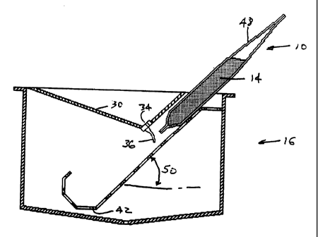
FIGS. 3 and 4 disclose a brew basket 16, which is designed to be used with
filter pouch
10 in a brewing process, as illustrated by FIGS. 5 through 9. Brewing basket
16 is used, for
example, with a commercial coffee brewing machine, such as a Bunn-O-Matic,
model no. 0L-35,
which is made by Bunn-O-Matic Corporation of Springfield, IL. The brewing
machine, not
shown, includes a refillable container of water, known as brew water or
brewing fluid, which
may be heated by heating elements within the machine.
The machine also includes a system for delivering heated brew water to a spray
head or
nozzle at a flow rate and in a time sequence determined within the machine.
Brew basket 16 is
preferably slidably engaged with the brewing machine directly under the spray
head such that the
brew basket may be removed for refilling with a fresh pouch, inserted for
brewing with the fresh
pouch located to receive brew water from the spray head, and then again
removed for used pouch
disposal. Brew basket 16 preferably has flanges 18 for engagement with the
brewing machine and
handle 20 for manually manipulating the brew basket with one hand. Brew basket
16 is
preferably a rectangular container with substantially open top 22 and closed
sides 24 and gently
sloped bottom 26. Bottom 26 preferably has an orifice 28 located at the center
of the sloped
bottom near the lowest portion of brew basket 16. Orifice 28 is intended to
discharge bypass brew
water and fluid extract from the brewing process to a container, not shown,
which is placed
directly below brew basket 16 in the brewing machine. A brewed fluid mixture
discharged to the
container is available for consumption after the brewing process is completed.
Brew basket 16 is preferably made of a heat-resistant plastic by a commonly
known
injection molding process. It may also be fabricated of metal, such as
aluminum sheet metal.
Brew basket 16 has an open brew water reservoir 30 located at top 22 and
facing upward to
CA 02362762 2001-08-23
WO 00/51480 PCT/US00/05295
7
receive brew water from a spray head. A principle purpose of reservoir 30 is
to receive brew
water no matter what kind of spray head is in the brewing machine and to
redirect the brew water
at a desired flow rate to a filter pouch. Reservoir 30 has at a bottom end 32
a plurality of drain
holes 34, which are located adjacent to a plurality of flexible fingers 36.
One flexible forger 36 is
positioned relative to one drain hole 34 such that any brew water flowing
through that drain hole
will flow over that flexible finger. Reservoir 30 is preferably made integral
with brew basket 16,
but is otherwise made of heat-resistant plastic or metal and is connected to
brew basket 16 by a
means not shown, such as snap-fitting, fusion welding, or other assembly
processes well known
in the art of rigid parts fabrication. Flexible fingers 36 are preferably
injection molded from
silicone rubber to be flexible, hydroscopic, and capable of withstanding
200°F temperatures.
Flexible fingers 36 are preferably connected to reservoir 30 by molding a
rectangular bar 37
containing all fingers, which snap fits into a groove at bottom end 32. Bar 37
could also have
drain holes 34 molded into it for accurate location relative to fingers 36.
Alternatively, threads of
silicone rubber could extend through drain holes 34 and be mechanically
fastened to the inside
surface of reservoir 30.
Brew basket 16 also has a filter pouch support member 38, which is fluid
permeable, but
sufficiently rigid to support filter pouch 10 during a brewing process.
Support member 38 is
preferably angled at 45° to horizontal, but may be inclined at an angle
ranging from about 30° to
about 60° for reasons which are discussed hereinafter. Support member
38 is preferably made
integral with brew basket 16, but is otherwise removable and made of heat-
resistant plastic,
metal, or metal wire. It is connected to brew basket 16 by a means not shown,
such as
snap-fitting, fusion welding, or other assembly processes well known in the
art of rigid parts
fabrication. Support member 38 may also be made of a perforated metal having a
plurality of
holes 40. Support member 38 has a bottom end 42 which supports a filter pouch
spaced above
bottom 26.
Support member 38 is located relative to reservoir 30 such that space is
provided between
them'to insert a filter pouch and such that flexible fingers 36 contact an
outer surface of the filter
pouch near an upper end thereof. Bottom end 42 has a hook-shaped portion 44 so
that when a
filter pouch is placed onto support member 38 and is wetted during the brewing
process, the filter
pouch will not slump further down the inclined support surface.
FIGS. S through 9 show steps of a brewing process using filter pouch 10 and
brew basket
16. FIG. 5 shows filter pouch 10 being placed into brew basket 16 between
support member 38
and reservoir 30. Flexible fingers 36 are deflected in order for filter pouch
10 to pass under them.
FIG. 6 shows filter pouch 10 located in position for brewing to commence.
Flexible fingers 36
CA 02362762 2001-08-23
WO 00/51480 PCT/US00/05295
8
remain deflected and in contact with an outer surface 46 of filter pouch 10
near an upper portion
48 thereof. The benefit offered by flexible finger contact with the outer
surface of the pouch is
believed to be a reduction in surface tension at the contact point so that
brew water may enter the
pouch with minimal resistance and thereby avoid external brew water runoff at
the outer surface.
Flexible fingers 36 preferably contact filter pouch 10 at a point above the
level of particles 14 so
that brew water may be directed into filter pouch 10 without interference from
particles 14.
However, flexible finger contact is desired near to the upper level of
particles 14 so that brew
water does not bypass particles 14 by passing through an opposite side of
filter pouch 14. The
ideal location of flexible fingers 36 is therefore a function of the angle
of.inclination 50 of filter
pouch 10. The steeper the angle, the higher fingers 36 may contact outer
surface 46 without
internal brew water bypass occurring.
The flexible fingers represent one embodiment of a brew water conduit in fluid
communication with and extending from a brew water reservoir. Such a conduit
could be a
hollow tube through which brew water could flow. It could also be a solid
strip of material over
which brew water could flow. The flexible fingers are preferred because they
provide the greatest
compliance to inserting and removing a filter pouch while ensuring contact
with the outer surface
of the filter pouch.
FIG. 7 shows a brew water 52 from a brewing machine spray head accumulating in
reservoir 30. Flow of brew water 52 through drain holes 34 over flexible
forgers 36 and into filter
pouch 10 and particles 14 cannot be seen in FIG. 7. Brew water infiltrates
particles 14 to brew a
fluid extract 54 from the particles. Fluid extract 54 consists of brew water
and solids dissolved
from particles 14.
FIG. 8 shows a condition of filter pouch 10 and brew basket 16 near the end of
brewing,
wherein the level of fluidized and expanded particles has risen within filter
pouch 10 and brew
water establishes a head near the point where flexible fingers 36 contact
outer surface 46. In the
prior art there are elaborate schemes for horizontally placed filter pouches
to expand vertically in
order to provide space for particle expansion and fluidization and suspension
of particles.
Because the filter pouch of the present invention is inclined and only
partially filled with
particles, it is not necessary for opposing sides of filter pouch 10 to
separate in order to generate
internal space. Instead, expansion occurs inside filter pouch 10 along its
axis of incline. If filter
pouch 10 is inclined at an angle less than 30° from horizontal, there
is likely more tendency for
the opposing sides of the pouch to try to separate than for particles to move
along an axis of
incline. Also, at lower angles of inclination, particle positioning at a
bottom end of the filter
pouch is not as consistent, and brew water may not fall onto particles. It may
instead pass through
CA 02362762 2001-08-23
WO 00/51480 PCT/US00/05295
9
the opposite side of the pouch and therefore bypass the particles. If filter
pouch 10 is inclined
more than about 60° from horizontal, the depth of brew basket 16 would
be excessive. Many
brewing machines have a fixed space between spray head and top of receiving
container for the
brew basket to be positioned. A shorter, fatter filter pouch may permit angles
of incline greater
than 60° to horizontal inside brew basket 16.
Meanwhile, fluid extract 54 from particles 14 is shown continuously exiting
filter pouch
everywhere around filter pouch 10 where particles 14 contact filter pouch 10.
Because fluid
extract 54 is higher in viscosity than brew water 52, and because particles 14
tend to fill pores in
filter pouch 10, it is desirable that the surface area available far fluid
extract 54 to exit filter
10 pouch 10 be significantly larger than the surface area available for brew
water 52 to enter filter
pouch 10, so that a substantial match in flow rates maintains a fluid head 56
within filter pouch
10. Fluid head 56 is preferably developed at least as great as the depth of
particles 14 in filter
pouch 10 during most of the brewing time so that a maximum number of particles
may be
infiltrated, fluidized, and suspended by brew water 52. FIG. 8 also shows a
pooling of fluid
extract within brew basket 16 at sloped bottom 26 behind orifice 28. Orifice
28 is preferably
sized large enough that it does not permit pooling of fluid extract 54 to a
level where it touches
filter pouch 10 so that the rate of discharge of fluid extract 54 from filter
pouch 10 is undisturbed.
Orifice 28 preferably centers a discharge stream 60 from brew basket 16 into a
container waiting
below brew basket 16. Multiple orifices may also be beneficial at bottom 26.
FIG. 9 shows the removal of used filter pouch 10 after brewing is completed.
Again,
flexible forgers 36 are deflected so that the pouch may pass out of brew
basket 16 the same way it
entered. Alternatively, if reservoir 30 is removable from brew basket 16,
reservoir 30 may first be
removed and then wet filter pouch 10 may be removed more easily.
In an alternative embodiment to the use of a brew basket 16, a filter pouch
may be
suspended vertically or inclined at an angle of at least 30° against a
support bar, and brew water
may be sprayed substantially perpendicular to an upper end of a filter pouch
so that brew water
enters the filter pouch without the need for flexible finger contact. In such
an embodiment (not
shown) brew water fluidizes particles in the filter pouch just as in the brew
basket embodiment.
However, fluid extract exiting the filter pouch falls directly from the filter
pouch into an open
container below: Thus, the brew basket of the present invention is unnecessary
in this
embodiment. However, means for suspending or otherwise supporting the filter
pouch is
necessary along with directed spray nozzles in the brewing machine.
Filter pouch 10 is a fully compliant pouch, constructed only of flexible
filter material in
order to minimize its manufacturing cost. There are other fully compliant
pouches in the prior art
CA 02362762 2001-08-23
WO 00/51480 PCT/US00/05295
which are intended to be laid flat in a brew basket with compliance intended
to seal the pouch
against the brew basket in order to minimize brew water bypass. However,
because the particle
location in a horizontally disposed pouch is unpredictable, such pouches are
known to provide
unreliable sealing. To overcome this problem, some prior art cartridges have
included rigid rim
5 portions which provide for more predictable sealing in a brew basket.
However, such a
compromise significantly increases the manufacturing cost of these cartridges.
The filter pouch of the present invention contrasts with the prior art because
a brew
basket and pouch seal is not required. In fact, in the alternative embodiment,
a brew basket is not
even needed. This is because the brewing system of the present invention
directs the brew water
10 into the inclined filter pouch so that an external fluid head of brew water
is not produced. The
fluid head of the present invention is located inside the pouch rather than
above it in a brew
basket. The benefits of the present invention are that pouch cost is minimized
and brew water
bypass is also minimized.
In other prior art filter pouches, brew water is directed into them by making
openings in
the pouches. Such openings reduce the potential for brew water bypass by
eliminating any filter
material resistance. However, any opening compromises the integrity of the
filter pouch. That is,
in handling the pouch after brewing, grounds may escape through the opening.
Since one of the
principle advantages of a pouch is to reduce particle contamination common
with open filters,
providing an opening for any reason is a severe negative. The pouch of the
present invention is
always maintained fully closed to prevent particles escaping. Brew water is
directed into filter
pouch 10 without the need for an opening therein.
In a preferred embodiment, filter pouch 10 preferably has dimensions of 12 cm
by 12 cm,
with an internal volume of approximately 300 ml. Brew basket 16 preferably has
outer
dimensions of 16 cm wide by 16 cm long by 10 cm high. Support member 38 is
preferably spaced
away from reservoir 30 by a distance of 2.5 cm to allow access for filter
pouch 10. Reservoir 30
preferably has a volume of about 150 ml . Drain holes 34 are preferably about
3 mm in diameter.
and there are preferably five of them centered about 4 cm from each edge of
brew basket 16.
Flexible fingers 36 are preferably about 1.5 mm in diameter and about 3 cm
long. Each finger
preferably extends through a drain hole.
While much of the foregoing discussion has focused upon the use of a single
filter pouch,
it should be understood that the principles of the present invention may be
applied to
configurations and processes utilizing a plurality of filter pouches in side-
by-side, fan-shaped, or
other arrangements which permit brewing in accordance with the present
invention.
CA 02362762 2001-08-23
WO 00/51480 PCT/US00/05295
11
While particular embodiments of the present invention have been illustrated
and
described, it will be obvious to those skilled in the art that various changes
and modifications
may be made without departing from the spirit and scope of the invention, and
it is intended to
cover in the appended claims all such modifications that are within the scope
of the invention.