Note: Descriptions are shown in the official language in which they were submitted.
CA 02362774 2001-08-31
WO 00/51701 PCT/US00/05809
IMPROVED WATER PURIFICATION PACK
Field of the Invention
The invention generally relates to water purification, and more particularly
to devices and methods for
purifying water to a quality suitable for medical applications.
Background of the Invention
Various medical conditions require treatments that call for the injection of
fluids into the human body. For
example, severe trauma to the human body often involves significant loss of
bodily fluids. Additionally, illnesses often
cause diarrhea followed by dehydration and ion imbalance. In order to
rehydrate the individual, injection of an
intravenous saline or dextrose solution is required. Other medical
applications (e.g., wound irrigation) require similar
fluid purity levels.
An example of the need for injection of fluids into the body is in the area of
dialysis. Treatments for patients
having substantially impaired renal function, or kidney failure, are known as
"dialysis." Either blood dialysis
("hemodialysis") or peritoneal dialysis methods may be employed. Both methods
essentially involve the removal of
toxins from body fluids by diffusion of the toxins from the body fluids into a
toxin free dialysis solution. Peritoneal
dialysis can be performed without complex equipment and in a patient's home.
In the peritoneal dialysis process, the
patient's peritoneal cavity is filled with a dialysate solution. Dialysates
are formulated with a high concentration of
the dextrose, as compared to body fluids, resulting in an osmotic gradient
within the peritoneal cavity. The effect of
this gradient is to cause body fluids, including impurities, to pass through
the peritoneal membrane and mix with the
dialysate. By flushing the dialysate from the cavity, the impurities can be
removed.
Due to indirect contact with bodily fluids through bodily tissues, rather than
direct contact with blood, the
dextrose concentration needs to be considerably higher in peritoneal dialysis
than in hemodialysis, and the treatment is
generally more prolonged. Peritoneal dialysis may be performed intermittently
or continuously. In an intermittent
peritoneal dialysis (IPD) procedure, the patient commonly receives two liters
of dialysate at a time. For example, in a
continuous ambulatory peritoneal dialysis (CAPD) procedure, the peritoneal
cavity is filled with two liters of dialysate
and the patient is the free to move about while diffusion carries toxins into
the peritoneal cavity. After about 4=6
hours, the peritoneum is drained of toxified dialysate over the course of an
hour. This process is repeated two to
three times per day each day of the week. Continuous Cycle Peritoneal Dialysis
(CCPD) in contrast, involves
continuously feeding and flushing dialysate solution through the peritoneal
cavity, typically as the patient sleeps.
Because peritoneal dialysates are administered directly into the patient's
body, it is important that the
dialysis solution maintains the correct proportions and concentrations of
reagents. Moreover, it is impractical to
formulate and mix dialysis solutions on site at the typical location of
administration, such as the patient's home.
Accordingly, peritoneal dialysates are typically delivered to the site of
administration in pre=mixed solutions.
Unfortunately, dialysis solutions are not stable in solutions over time. For
example, dextrose has a tendency
to caramelize in solution over time, particularly in the concentrations
required in the peritoneal dialysis context. To
prevent such caramelization, peritoneal dialysis solutions are typically
acidified, such as with hydrochloric acid, lactate
-1-
CA 02362774 2001-08-31
WO 00/51701 PCT/US00/05809
or acetate, to a pH between 4.0 and 6.5. The ideal pH level for a peritoneal
dialysate, however, is between 7.2 and
7.4. While achieving the desired goal of stabilizing dextrose in solution, the
pH of acidified peritoneal dialysis solutions
tends to damage the body's natural membranes after extended periods of
dialysis. Additionally, the use of acidified
peritoneal dialysates tends to induce acidosis in the patient.
Bicarbonates introduce further instability to dialysis solutions. The most
physiologically compatible buffer
for a peritoneal dialysate is bicarbonate. Bicarbonate ions react undesirably
with other reagents commonly included in
dialysate solutions, such as calcium or magnesium in solution, precipitating
out of solution as insoluble calcium
carbonate or magnesium carbonate. These insolubles can form even when the
reactants are in dry form. When
occurring in solution, the reactions also alter the pH balance of the solution
through the liberation of carbon dioxide
(CO2). Even in the absence of calcium or magnesium salts, dissolved sodium
bicarbonate can spontaneously
decompose into sodium carbonate and COZ, undesirably lowering the solution's
pH level.
Accordingly, a need exists for improved methods and devices for formulating
solutions for peritoneal dialysis.
Desirably, such methods and devices should avoid the problems of non-
physiologic solutions and incompatibility of
dialysate reagents, and also simplify transportation, storage and mixing of
such dialysates. One aspect of this
problem is the need for mechanisms for safely and completely mixing
constituents of dialysates in diluent at the point
of administration. Another aspect of this problem is the need for producing
injectable quality water or other diluent at
the point of administration.
It is often advantageous to provide purified fluid independently of other
constituents in the injected fluid. In
many situations, independent provision of purified water simplifies transport
and storage of solution constituents. In
the case of peritoneal dialysis, preparing dialysate solution from dry
reagents and independently provided pure water
also minimizes the time for which unstable solutions must be stored prior to
administration. Similarly, many other
unstable solutions should be prepared soon before administration, preferably
at the site of administration.
On site purification of fluids is also advantageous in a number of other
medical applications, including
intravenous injection, intramuscular injection, orally administered fluids,
wound irrigation, use in instrument cleaning
solutions, and general employment by immuno-compromised individuals (e.g.,
AIDS patients, geriatrics, etc.).
While separating provision of injectable quality fluid from other constituents
can simplify transportation and
delay production of unstable solutions, transporting purified water to the
site of administration, even if produced and
shipped separately from dry reagents, can represent considerable costs, as
well as introducing opportunities for
contamination. Transportation costs and contamination are particularly
problematic when fluids are to be
administered outside of a controlled hospital or clinic environment. Problems
are even further exacerbated in lesser-
developed countries, such as in the Indian subcontinent and Africa. Even in a
hospital setting, the ability to convert
available water into injectable quality water on site can reduce
transportation and storage costs as well as avoiding
the risk of contamination during transportation and storage.
Therefore, a need exists for a method and apparatus that allow preparation of
injectable quality fluid from
available fluid. Desirably, the apparatus should be transportable and
convenient for on-site use in remote locations.
-2-
CA 02362774 2006-11-29
Summary of the Invention
In satisfying the aforementioned needs, the embodiments described herein
provide a
portable apparatus and method for purifying fluid to levels suitable for
medical applications,
including injection into the human body.
In accordance with one aspect of the present invention, a portable apparatus
is
provided for producing injectable quality fluid. The apparatus includes a
housing that defines
a fluid flow path from an inlet port to an outlet port. A depth filtration
stage, an organic
filtration component, a deionization resin bed and a permeable membrane are
held within the
housing along the fluid flow path. The permeable membrane has a porosity of
less than about
0.5 m and is configured to retain endotoxins.
In accordance with another aspect of the present invention, a water
purification pack
for producing injectable quality water includes a container. The container
defines a flow-
through path from an inlet to an outlet with an average cross-sectional area
of less than about
square inches. The container houses purification elements within the path,
including a
15 permeable membrane having a porosity of no more than about 0.5 m. The
purification
elements provides a back-pressure low enough to allow fluid flow greater than
about 30
mL/min under a feed pressure of between about 5 psi and 10 psi.
In accordance with another aspect of the invention, a method is provided for
producing injectable quality water. The method includes providing a portable
purification
20 pack with a housing surrounding purification elements in series. Non-
sterile water is
provided to an inlet of the housing under a feed pressure of less than about
20 psi. The water
passes through the purification elements. Purified water exits from an outlet
of the housing.
The purified water has an organic content, conductivity, pH level and
particulate
contamination level suitable for injection into the human body.
In accordance with another aspect of the invention, there is provided a system
comprising a single housing having a diluent inlet and a solution outlet, the
single housing
containing a compression component, and at least one reagent bed comprising
reagent in dry
form, wherein the reagent is present in a proportion sufficient for production
of a complete
dialysis solution.
In accordance with another aspect of the invention, there is provided a method
for
producing a hernodialysate solution, comprising:
passing diluent through a dry reagent bed, thereby consuming reagents in the
bed;
carrying the consumed reagents with the diluent out of the bed; and
compacting the reagent bed as the reagents are consumed.
In accordance with another aspect of the invention, there is provided a device
storing
and delivering dry reagents for medical fluids, comprising a single housing
with a diluent
-3-
CA 02362774 2006-11-29
inlet and a solution outlet, the housing containing a compression component
and at least two
discrete reagent beds.
Brief Description of the Drawings
These and other aspects of the invention will be apparent to the skilled
artisan in view
of the Detailed Description and claims set forth below, and in view of the
appended drawings,
which are meant to illustrate and not to limit the invention, and wherein:
Figure 1 is a schematic side perspective view of a system for producing
peritoneal
dialysate or other medical solutions;
Figure 2 is a schematic side sectional view of a fluid purification pack,
constructed in
accordance with one aspect of the present invention;
Figure 3 is a schematic side sectional view of a reagent cartridge for housing
reagents
of peritoneal dialysate;
Figure 4 shows the reagent cartridge of Figure 3 after partial dissolution of
the
reagents housed therein;
Figure 5 shows the reagent cartridge of Figure 3 after complete dissolution of
the
reagents housed therein;
Figure 6 is a schematic side sectional view of a reagent cartridge for housing
reagents
of peritoneal dialysate;
Figure 7 shows the reagent cartridge of Figure 6 after complete dissolution of
the
reagents housed therein;
-3a-
CA 02362774 2005-03-16
inlet and a solution outlet, the housing containing a compression component
and at least two
discrete reagent beds.
Brief Description of the Drawings
These and other aspects of the invention will be apparent to the skilled
artisan in view
of the Detailed Description and claims set forth below, and in view of the
appended drawings,
which are meant to illustrate and not to limit the invention, and wherein:
Figure 1 is a schematic side perspective view of a system for producing
peritoneal
dialysate or other medical solutions;
Figure 2 is a schematic side sectional view of a fluid purification pack,
constructed in
accordance with one aspect of the present invention;
Figure 3 is a schematic side sectional view of a reagent cartridge for housing
reagents
of peritoneal dialysate;
Figure 4 shows the reagent cartridge of Figure 3 after partial dissolution of
the
reagents housed therein;
Figure 5 shows the reagent cartridge of Figure 3 after complete dissolution of
the
reagents housed therein;
Figure 6 is a schematic side sectional view of a reagent cartridge for housing
reagents
of peritoneal dialysate;
Figure 7 shows the reagent cartridge of Figure 6 after complete dissolution of
the
reagents housed therein;
-3a-
CA 02362774 2001-08-31
WO 00/51701 PCTIUSOO/05809
Figures 8A and 8B illustrate side sectional and plan views, respectively, of a
downstream end of the water
purification pack of Figure 2;
Figures 9A and 9B illustrate side sectional and plan views, respectively, of
an upstream end of the reagent
cartridge of Figure 3, configured to irreversibly connect with the water
purification pack; and
Figure 10 is a side sectional view of a coupling between the water
purification pack and reagent cartridge of
Figures 8 and 9.
Detailed Description of the Preferred Embodiment
While the illustrated embodiments are described in the context of a particular
application, i.e., peritoneal
dialysis, the skilled artisan will find application for the apparatus and
methods for producing injectable quality fluid in
a variety of medical applications. Moreover, the apparatus and methods for
producing "injectable quality" fluids will
have applications beyond the medical field, wherever similarly pure water is
desirable. The fluid purification unit
described herein has particular utility when connected in series upstream of
fluid collectionldelivery devices, such as
the illustrated mechanism for mixing dry reagent as purified diluent flows
through.
System for Preaaring Peritoneal Dialysis Solution
Figure 1 illustrates a system 10 for producing solutions suitable for
injection into the human body. A diluent
or fluid purification pack 12, as described in more detail below, is connected
upstream of a reagent cartridge 14. The
cartridge 14, in turn, is in fluid communication with a solution reservoir 16
via a tube 18. As also set forth in more
detail below, purified diluent is provided from the pack 12 to the reagent
cartridge 14, wherein the dry reagents are
dissolved and solution is delivered to the reservoir 16. Alternatively, the
solution can be delivered directly to the
patient's body.
In the illustrated embodiment, the solution comprises peritoneal dialysis
solution. The cartridge 14
advantageously houses dry or lyophilized formulations of reagents suitable for
peritoneal dialysis. Desirably, the
solution is formed immediately prior to delivery to the patient's peritoneal
cavity, such that the dialysate need not be
stored in solution form for extended periods, and little opportunity exists
undesirable reactions within the solution prior
to delivery.
The cartridge 14 defines fluid flow paths through the dry reagents, by way of
porous elements
therebetween, enabling dry storage in confined reagent beds while also
enabling dissolution simply by passing diluent
through the housing. Two preferred versions of the cartridge 14 are described
in more detail with respect to Figures
3-7, below.
The diluent purification pack 12 of the illustrated embodiment is capable of
on-site purification of locally
available fluid, such as tap water from a municipal water source. The
preferred water purification pack is described in
more detail with respect to Figure 2 below.
Water Purification Pack
Referring to Figure 2, the preferred fluid purification pack 12 is capable of
purifying water or other liquid
diluent to the standards required for injection into a patient, e.g., for
peritoneal dialysis applications. Advantageously,
-4-
CA 02362774 2001-08-31
WO 00/51701 PCT/USOO/05809
available water, preferably potable water, can be introduced to the system,
and is purified as it flows through the
pack. The purified water can be delivered, for example, directly to the
reagent cartridge 14 (Figure 1), to a storage or
collection container for short-term storage or transportation or direct
connection to line.another delivery device, such
as a wound irrigation pump. Accordingly, bulky purified water need not be
stored long in advance of its need or
transported great distances to the point of administration. Complex machinery
for purifying water is also obviated.
In order to serve as a diluent for injection into the human body, or for
similar applications, the independently
provided water must be highly purified. The U.S. Pharmacopoeia provides
processes for producing sterile water for
injection. The preferred water pack 12 also produces water of a quality
suitable for injection, preferably equivalent to
or surpassing the quality produced by the U.S. Pharmacopoeia processes. Water
purified through the pack thus
preferably meets or exceeds the U.S. Pharmacopoeia's standards for Sterile
Water for Injection, including sterility, pH,
ammonia, calcium, carbon dioxide, chloride, sulfate and oxidizable substances
tests. In particular, injectable quality
water or other fluid produced by the illustrated water purification pack 12
exhibits the following characteristics: a
very low level of total organic carbon, preferably less than about 1 ppm and
more preferably less than about 500 ppb;
low conductivity, preferably less than about 5.0 Siemens (2.5 ppm) and more
preferably less than about 2.0 ,u
Siemens (1 ppm); near neutral pH, preferably between about 4.5 and 7.5, and
more preferably between about 5.0 and
7.0; very low particulate concentration, preferably fewer than less than about
12 particleslmL of particles >_ 10 m,
more preferably less than about 6 particleslmL of such particles, and
preferably less than about 2 particleslmL of
particles _ 25 m, more preferably less than about 1 particlelmL of such
particles; and low endotoxin levels,
preferably less than about 0.25 endotoxin units (EU) per mL (0.025 nglmL),
more preferably less than about 0.125
EUImL (0.0125 nglmL) with a 10:1 EUing ratio.
Conventionally, purifying non-sterile fluid to such stringent quality
standards, particularly for introduction
into the human body, has called for extensive mechanical filtration andlor
distillation, pumping, distribution and
monitoring systems. These complex mechanisms can safely and economically
produce large volumes of sterile water
to injectable quality. Such mechanisms, however, occupy considerable space at
a central location and necessitate
even more space for storing purified water closer to the site of
administration. Moreover, conventional water
purification mechanisms are not conducive to employment in a portable
apparatus for use in the field.
U.S. Patent No. 5,725,777 to Taylor discloses a portable apparatus for
purifying water to injectable quality.
The apparatus includes several stages for purification, including multistage
depth prefiltering, ultrafiltration fibers,
reverse osmosis fibers, ion exchange resin and activated carbon in that order.
The reverse osmosis stage of Taylor '777 effectively purifies water to a high
degree. Unfortunately,
because reverse osmosis involves diffusing input water across a semi-permeable
membrane, the rate of water
production is very slow relative to the cross-section of the membrane. Even
with the use of multiple reverse osmosis
fibers with a high overall membrane surface area, diffusion is slow. In order
to fully realize the advantages of
portability, purified diluent should be rapidly produced at the time of
administration. For acceptable rates using the
apparatus of Taylor '777, however, high pressures (e.g., 40 to 75 psi) are
applied across the semi-permeable
-5-
CA 02362774 2001-08-31
WO 00/51701 PCT/USOO/05809
membrane. Pumps and restrictor means for realizing these pressures reduce the
versatility and portability of the
overall system.
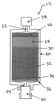
In the illustrated embodiment, the water or fluid purification pack 12
comprises a housing 20 with an axial
inlet 22 and outlet 24. The housing 20 defines a flow path between the inlet
22 and outlet 24, with multiple
purification stages along the flow path. The pack 12 is thus designed to
purify fluid in the course of traveling,
preferably in a linear path, through the housing 20.
The housing 20 is preferably formed of a suitable polymer, particularly
polycarbonate, which aids in purifying
water by binding endotoxins through charge interactions. Endotoxins are the
organic byproduct of dead
microorganisms, particularly the outer cell wall of bacteria. Although the
term endotoxin is occasionally used to refer
to any "cell-associated" bacterial toxin, it primarily refers to the
Iipopolysaccharide complex associated with the outer
envelope of Gram-negative bacteria such as E. coli, Salmonella, Shigella,
Pseudomonas, Neisseria, Haemophilus, and
other leading pathogens. In high enough concentrations, particularly in
critical applications such as intravenous
injection, this organic matter can be toxic.
The pack 12 is configured for convenient portability. The skilled artisan will
appreciate the fact that
different sizes will safely produce different amounts of purified water. Thus,
for an embodiment optimized for safely
purifying 10 L of water, the outside dimensions of the housing 20 preferably
include a length of less than or equal to
about 6 inches from inlet 22 to outlet 24, and a width (diameter in the
illustrated embodiment) of less than or equal to
about 5 inches. The illustrated housing 20, designed for safely purifying 2 L
of water, has a length of about 3 inches
and a diameter of about 2.25 inches. Preferably, therefore, the fluid
purification pack 12 has a cross-sectional area of
less than about 20 sq. inches, more preferably less than about 4 sq. inches.
Despite this small cross-section, the
illustrated pack 12 can achieve high flux rates under pressures as low as
about 5-10 psi.
The fluid purification pack 12 is also preferably configured to deliver a unit
dose of purified fluid. The pack
12 thus is preferably designed for one-time use and to be discarded
thereafter. As such, the sterility of the pack 12
can be assured, since the pack 12 will not be reused after seals at the inlet
22 and outlet 24 are broken. Several of
the features described hereinbelow discourage or prevent recharging the water
pack 12 for repeated use, as will be
understood by the skilled artisan.
Downstream of the inlet 22 is a depth filter 26. The porosity limit of the
illustrated depth filter 26
preferably ranges from about 1 micron ( m) to 10 m, most preferably about 1
m. The depth filter 26 is preferably
formed of a porous polypropylene mesh in multiple layers, particularly two to
four layers. Alternatively, the
commercially available cellulose-based depth filters can be employed, as will
be understood by one of ordinary skill in
the art. In still other arrangements, ceramic or other known particle
filtration material can be employed. Most
preferably, the depth filter 26 comprises a series of depth filters (not
shown) that successively filter out smaller and
smaller particles. In the illustrated embodiment, four successive depth
filters are included within the depth filtration
stage 26, having porosities of about 100 m, 40 m, 10 m and 1 m in sequence
from upstream end to
downstream end.
-6-
CA 02362774 2001-08-31
WO 00/51701 PCT/US00/05809
Downstream of the depth filter 26 is an organic filtration stage 28, which can
comprise a bed of granular
carbon. In the illustrated embodiment, the organic filtration stage comprises
a resin bed treated for retention of
organic contaminants. The illustrated embodiment incorporates a form of
styrene divinylbenzene commercially
available from Rohm & Haas of Philadelphia, PA under the trade names Ambersorb
563. This component removes
certain residual organic contaminants, such as endotoxins, as well as commonly
used additives placed in municipally
treated waters (e.g., chlorine, trihalomethanes and chloramine).
Adjacent to the downstream end of the organic filtration stage 28 is a
restraint 30. The restraint 30 is a
filter of controlled porosity, preferably also comprising a polypropylene mesh
with a porosity of about 1-10 microns,
more preferably about 1 micron. This component prevents passage of
particulates shed by the organic filtration
component 28, as well as providing a secondary assurance that insoluble
particulates do not pass further through the
water purification pack.
Adjacent to the downstream side of the restraint 30 is a deionization stage,
preferably comprising a bed 32
of deionization resin beads. The resin bed 32 more preferably comprises a
mixture of pharmaceutical grade resins
with strong anion exchanger (cation-impregnated) and strong cation exchanger
(anion-impregnated) chemistries,
binding dissociable ions and other charged particles with a very high
affinity. In the illustrated embodiment, the resin
bed 32 comprises mixed anion- and cation-impregnated resin beads with weakly
associated hydrogen or hydroxyl
groups, respectively. The ion exchange resins of the preferred embodiment
comprise styrene divinyl benzene. Such
resins are available, for example, from Rohm & Haas of Philadelphia, PA under
the trade name IRN 150, or from
Sybron of Birmingham, NJ under the trade name NM60. Cation exchangers exchange
hydrogens for any dissolved
cations in the diluent. Common dissolved cations include sodium (Na'), calcium
(Ca2+) and aluminum (AI3'). The anion
exchange resins exchange hydroxyl ions for any anions present in an aqueous
solution. Common anions include
chloride (Cf) and sulfides (SZ-). The resin bed 32 additionally retains some
endotoxins that escape the upstream
filtration components. The skilled artisan will recognize other types of ion-
exchange resins that could also be utilized
in this stage.
The preferred mixed resin bed 32 simplifies and provides a more compact pack
12 than more conventional
ion exchange columns, wherein anion and cation exchangers are separated.
Moreover, the mixed bed 32 arrangement
prevents recharging the ion exchange resin by back-flushing, thus discouraging
re-use and maintaining sterility of the
unit.
Downstream of the deionization resin bed 32 are a deionization bed restraint
34 and a terminal filter element
36, in sequence. The restraint 34 preferably comprises the same polypropylene
mesh utilized for the illustrated depth
filter 26 and carbon bed restraint 30. The resin bed restraint 34 serves to
prevent passage of deionization bed
fragments or fines, as well as any other particulates that have escaped the
upstream filters 26, 30. The restraint 34
also serves to protect the filter element 36 downstream of the restraint 34.
The terminal filter element 36 comprises a permeable membrane, preferably a
microfiltration or ultrafiltration
membrane, depending upon the application. The term "terminal," as utilized in
this context, refers to the filtration
-7-
CA 02362774 2001-08-31
WO 00/51701 PCTIUSOO/05809
element with the lowest porosity, and not the physical location. Typically,
however, the terminal filter will be
immediately adjacent the outlet, as shown, such that large particulates are
filtered out by courser filtration elements
upstream of the terminal filter. The terminal filter 36 preferably has a
porosity of at most about 0.5 m, and none
preferably less than about 0.22 m.
For applications in remote locations where water is untreated or
insufficiently treated, an ultrafiltration
membrane is most preferable. Nominal porosity of between about 10,000 and
30,000 molecular weight cut-off
desirably filters out viruses prevalent in such locations, such as hepatitis,
rota virus, polio, etc. Nominal cut-off for the
illustrated embodiment is between about 15,000 and 25,000 MW. While endotoxins
(complex lipopolysaccaride)
generally aggregate into complexes of greater than about 1,000,000 molucular
weight, an ultrafiltration membrane
can retain even a single unit of endotoxin (about 15,000 molecular weight).
For employment in more developed locations, where treated water is available
(e.g., municipal water in most
American cities), the water purification pack 12 need not filter out
pathogenic viruses. Accordingly, for such uses the
terminal filter 36 comprises a microfiltration membrane. Advantageously, the
higher porosity of a microfiltration
membrane allows a greater flow rate for a given feed pressure or a lower feed
pressure for a given flow rate. The
microfiltration membrane preferably has a porosity of lower than about 0.5 m,
and more preferably comprises a 0.22
m or finer filter, and most preferably has a porosity of about 0.20 m or
finer. Desirably, the terminal filter 36 has
enhanced endotoxin binding characteristics and is preferably chemically
treated to incorporate a quaternary amine
exchanger (QAE) to bind endotoxins. Such endotoxin binding membranes are
available under the trade name HP200
from the Pall Specialty Materials Co. Most preferably, the terminal filter 36
comprises two successive QAE-treated
0.20 m permeable membranes, ensuring adequate endotoxin retention. Despite a
high flux rate compared to
ultrafiltration membranes, therefore, the terminal filter 36 incorporating a
microfiltration membrane removes
endotoxins as well as microbes and particulate matter of less than 1 m from
diluent passing therethrough. In fact,
challenge water with endotoxin levels as high as 1,000 nglmL have been
purified through the illustrated pack 12 to
below the current detection limit (0.006 nglmL).
The purification stages within the water purification pack are thus such that
water passing through the pack
12 and exiting the housing outlet 24 is of a purity level safe for injection
into the human body (following the addition
of appropriate salts for physiologic solutions). Preferably, effluent water
conforms to the purity levels set forth
above. It will be understood, of course, that while safe enough for injection,
the fluid may actually be employed for
alternative medical applications, such as wound irrigation, use in instrument
cleaning solutions, and general
employment by immuno-comprised individuals (e.g., AIDS patients, geriatrics,
etc.).
Desirably, the water purification pack 12 includes an upstream cap 38 over the
housing inlet 22, and a
downstream cap 40 over the housing outlet 24. The sterility of the
purification elements housed within the housing
20 is thus maintained until use. As will be understood in the art, the inlet
22 and outlet 24 can be provided with
threads or Luer-type fittings (see Figures 8-10) to mate with upstream and
downstream elements in the peritoneal
dialysate delivery system 10 (Figure 1).
-8-
CA 02362774 2001-08-31
WO 00/51701 PCTIUSOO/05809
The sterility and efficacy of the water purification pack 12 is also
reinforced by features discouraging re-use
of the water pack. As previously noted, the resin bed 32 preferably comprises
a mixed bed of anion- and cation-
exchangers. Thus, the mixed bed 32 cannot be recharged by traditional
backflushing techniques, since regeneration of
the cation-exchanger would result in exhaustion of the anion exchanger and
vice versa.
Additionally, the water purification pack is preferably configured to
irreversibly connect with a downstream
collection device. In one preferred arrangement, the housing outlet 24 is
welded or otherwise integrally connected
with a collection tube leading to a collection bag or other container. When
water is purified by passing through the
housing 22 and fills the downstream collection container, the preferred
plastic tubing is simultaneously cut and
cauterized to seal the tube downstream of the outlet 24, preventing re-use of
the water pack 12.
With reference to Figures 8 and 9, in another preferred arrangement, the
outlet 24 is irreversibly connectable
with the downstream reagent cartridge 14. The water pack outlet 24 and the
reagent cartridge inlet 52 thus have
interlocking mechanisms that are irreversible without damage to the
mechanisms.
In the illustrated embodiment, the water pack housing 20 includes a
cylindrical collar 42 surrounding the
outlet 24, the collar having outer ratcheting teeth 44. The reagent pack 14
includes a similar cylindrical collar 46
surrounding the inlet 52, and the collar 46 includes internal ratchet teeth
48. The outer collar 46 of the reagent pack
14 is sized to fit over the outer collar 42 of the water pack 12. The
ratcheting teeth 44, 46 are sloped to slide past
each other during clockwise rotation to tighten the inner Luer lock mechanism.
The teeth 44, 46 engage one another,
however, to prevent counter-clockwise rotation, such that the Luer lock cannot
be loosened.
Accordingly, the locking mechanism must be broken or otherwise damaged to
separate the used water pack
12 from the reagent cartridge 14. Such damage or breakage minimizes the risk
of accidentally re-using a spent water
pack 12. The skilled artisan will readily appreciate that similar irreversible
locking mechanisms can be utilized with
other collection or delivery devices downstream of the water purification
pack. The skilled artisan will also recognize
other suitable irreversible locking mechanisms for discouraging re-use.
Single-Bed Reagent Cartridge
Figures 3-5 illustrate a single-bed reagent cartridge 14 for use with the
water purification pack. The figures
illustrate various stages of dissolution, as will be better understood from
the methods of operation discussed
hereinbelow.
Figure 3 shows a fully charged reagent cartridge 14, in accordance with the
first embodiment. The cartridge
14 comprises rigid walled housing 50 with an inlet port 52 at an upstream end,
and an outlet port 54 at a downstream
end. Within the housing, a number of porous elements define a fluid flow path
between the inlet port 52 and the
outlet port 54.
The housing 50 is preferably transparent or translucent, advantageously
enabling the user to observe the
operation of the device and complete dissolution of reagents prior to use of a
produced solution, as will be apparent
from the discussion of the method of operation, discussed hereinbelow.
Examples of translucent and transparent
polymers are polypropylene, polycarbonate and many other well-known materials.
-9-
CA 02362774 2001-08-31
WO 00/51701 PCTIUSOO/05809
Within the housing 50, immediately downstream of the inlet port 52, is an
inlet frit 56, which serves as a
safety filter to contain any reagent which escapes the restraints described
below. An outlet frit 58 serves a similar
function immediately upstream of the outlet 54. Desirably, the inlet frit 56
and the outlet frit 58 comprise porous
elements having a porosity smaller than the smallest particle of the reagents
housed within the cartridge 14. The frits
56, 58 thus serve as filters to ensure that no reagent escapes the cartridge
prior to dissolution, as will be described
below. An exemplary frit is a multilayered polypropylene laminate, having a
porosity between about 1 m and 100
m, more preferably between about 10 m to 50 m. Further details on the
preferred material are given below, with
respect to the reagent restraints.
Downstream of the inlet frit 56 is an upstream reagent compression component
60. Similarly, upstream of
the outlet frit 58 is a downstream reagent compression component 62. The
compression components 60, 62
preferably comprise materials that have sponge-like elasticity and, as a
result of compression, exert axial pressure
while trying to return to its original, expanded form. The compression
components 60, 62 preferably comprise
compressible, porous, open cell polymer or foam, desirably more porous than
the frits, to avoid generation of back
pressure. An exemplary material for the compression components is a
polyurethane foam. Desirably, the compression
components 60, 62 and surrounding housing 50 are arranged such that the
compression components 60, 62 exert a
compressive force on the reagent bed regardless of the size of the reagent
bed. In other words, the compression
components 60 and 62 would, if left uncompressed, together occupy a greater
volume than that defined by the
housing 50. Desirably, the pressure exerted is between about 50 grams per sq.
inch and 2,000 grams per sq. inch,
more preferably between about 300 grams per sq. inch and 900 grams per sq.
inch.
It will be understood that, in other arrangements, metal or polymer coiled
springs and porous plates can
serve the same function. Such alternative compression components are
disclosed, for example, with respect to
Figures 12-15; Col. 9, lines 8-53 of U.S. Patent No. 5,725,777, the disclosure
of which is incorporated herein by
reference. Another preferred compression component is disclosed in U.S.
provisional application No. 601132,088, filed
April 30, 1999, the disclosure of which is hereby incorporated by reference.
It will also be understood, in view of the
discussion below, that a single compression component can serve the function
of the illustrated two compression
components. Two components exerting pressure on either side of a reagent bed
64(described below), however, has
been found particularly advantageous in operation.
A single reagent bed 64 is situated between the compression components 60, 62.
The reagent bed 64 is
desirably sandwiched between an upstream reagent restraint 66 and a downstream
reagent restraint 68. The
upstream reagent restraint 66 is thus positioned between the reagent bed 64
and the upstream compression
component 60, while the downstream reagent restraint 68 is positioned between
the reagent bed 64 and the
downstream compression component 62.
The restraints 66, 68 desirably prevent the passage of reagent particles in
their dry formulation. The
porosity of the restraints is therefore selected to be tess than the size of
the smallest particles within the reagent bed,
depending upon the particular reagent formulations and physical particle size
desired. Desirably, the pores are large
-10-
CA 02362774 2001-08-31
WO 00/51701 PCT/US00/05809
enough to avoid excessive pressure drop across the restraints. Preferably, the
restraint porosity in the range between
about 1 m and 100 m, more preferably between about 10 m to 50 m. An
exemplary restraint, suitable for the
illustrated peritoneal dialysis application, comprises the same material as
the frits 56, 58, and consists of a non-
woven polymer, particularly polypropylene with a porosity of about 20 microns.
Another exemplary restraint
comprises sintered polyethylene with a porosity of about 30 microns.
Additionally, the restraints 66, 68 are sized and shaped to extend completely
across the housing 50, forming
an effective seal against reagent particulates escaping around the restraints
66, 68.
The reagent bed 64 comprises a complete formulation of dry or lyophilized
reagents required to produce a
peritoneal dialysis solution. In the illustrated single-bed embodiment, the
reagent bed 65 is a mixture of compatible
reagents, such as will not exhibit spontaneous chemical reaction from
prolonged contact in their dry form.
Accordingly, a buffering agent such as an acetate or lactate, and particularly
sodium lactate, is employed in place of a
bicarbonate. Further reagents include electrolytes, such as sodium chloride,
magnesium.chloride, potassium chloride
and calcium chloride; a sugar, preferably dextrose; and an acid, particularly
citric acid. Advantageously, the acid
component of the reagent bed 65 can be lower than conventional solutions,
since storage in dry form alleviates the
tendency for dextrose caramelization.
The illustrated housing 50 holds reagents sufficient to produce 2 liters of a
typical peritoneal dialysate
solution. Accordingly, the reagent bed 64 holds the following reagents:
TABLE I
Dry Reagent Constituents Mass Dry Volume
Calcium chloride 514 mg Negligible
Magnesium chloride 101.6 mg Negligible
Sodium lactate 8.96 g 24 mL
Sodium chloride 10.76 g 22 mL
Dextrose 50 g 70 mL
Total 70g 116 mL
The dry volume of the above-listed reagents, which can produce 2 L of 2.5%
dextrose peritoneal dialysate, is
thus about 100 mL. The housing 50 for such a formulation need only be about
125% to 500% of the dry reagent
volume, more preferably about 150% to 200%, depending upon the selected
compression components 60, 62. The
illustrated housing 50 is about 2" in diameter and about 3" in height, thus
occupying about 175 mL. The cartridge 14
thus represents a much smaller and more stable form of dialysate for storage
and transport, compared to 2 L of
prepared solution. If a smaller or larger volume of solution is desired, the
skilled artisan can readily determine the
proportionate weight and volume of dry reagents required in the reagent bed
64, such as for producing 1 L, 3 L, 6 L,
-11-
CA 02362774 2001-08-31
WO 00/51701 PCTIUSOO/05809
L, etc. Similarly, the skilled artisan can readily determine the proportions
of reagents desirable for 1.5 % dextrose
dialysate, 4 % dextrose dialysate, etc.
An inlet port cover 70 and an outlet port cover 72 cover the housing inlet
port 52 and outlet port 54,
respectively. The port covers 70, 72 advantageously seal out moisture and
prevent destabilization of the dry reagents
5 housed within during transport and storage. As with the water purification
pack, the inlet port 52 and outlet port 54
can be configured with threaded or Luer-type connection fittings. In the
illustrated embodiment, the inlet port 52 is
configured to mate with the outlet 24 of the water purification pack 12
(Figure 2), while the outlet port 54 is
configured to mate with the downstream tube 18 (see Figure 1).
Double-Bed Reanent Cartridge
10 Figures 6 and 7 illustrate a double-bed reagent cartridge 14'. Figures 6
and 7 illustrate the cartridge 14' in
fully charged and fully depleted conditions, respectively, as will be better
understood from the methods of operation
discussed hereinbelow.
With reference initially to Figure 6, the housing 50 of the double-bed reagent
cartridge 14' is preferably
similar to that of the first embodiment, such that like reference numerals are
used to refer to like parts. Thus, the
housing 50 defines an inlet port 52 and outlet port 54, and contains porous
elements between the inlet port 52 and
outlet port 54, such as to define a fluid flow path through the housing 50.
Specifically, the housing 50 contains an
upstream frit 56, upstream compression component 60, upstream reagent
restraint 66, downstream reagent restraint
68, downstream compression component 62 and downstream frit 58. Each of these
elements can be as described
with respect to the previous embodiment.
Unlike the single-bed cartridge 14 of Figures 3-5, however, multiple reagent
beds are confined between the
upstream restraint 66 and downstream restraint 68. In particular, a primary
reagent bed 80 and a secondary reagent
bed 82 are shown in the illustrated embodiment, separated by at least one
restraint. In the illustrated embodiment,
the reagent beds 80 and 82 are separated by a first intermediate restraint 84
and second intermediate restraint 86,
as well as an intermediate compression component 88 between the intermediate
restraints 84 and 86.
Accordingly, the primary reagent bed 80 is confined between upstream restraint
66 and the first
intermediate restraint 84, while the secondary reagent bed 84 is similarly
confined between the second intermediate
restraint 86 and the downstream restraint 68. The intermediate reagent bed
restraints 84, 86 desirably serve to
contain the reagents within the beds 80, 82 in their dry form, while still
being porous enough to allow diluent, along
with any dissolved reagents, to pass through. Accordingly, the intermediate
reagent restraints 84, 86 can have the
same structure as the frits 56, 58 and upstream and downstream reagent
restraints 66, 68, as described above with
respect to the single-bed embodiment. Similarly, the intermediate compression
component 88 can have the same
structure as the upstream and downstream compression components 60, 62.
Each of the intermediate compression component 88 and the intermediate reagent
restraints 84, 86 are
interposed between and separate the primary reagent bed 80 from the second
reagent bed 82. Due to the selected
-12-
CA 02362774 2001-08-31
WO 00/51701 PCT/US00/05809
porosity of the elements, particularly the intermediate restraints 84, 86,
constituents of the two reagent beds 80, 82
therefore do not interact with one another in their dry states.
The illustrated double-bed embodiment therefore enables separate storage of
different reagents within the
same housing 50. A complete formulation of the dry reagents required to
produce a peritoneal dialysis solution may
contain reagents that react undesirably when exposed to one other for
prolonged periods of time, in either dry or liquid
forms, as noted in the Background section. For example, bicarbonates are
preferred, physiologically compatible
buffering agents for peritoneal dialysis, but tend to be very reactive with
typical salts in the dialysate formulation,
such as calcium chloride or magnesium chloride. The reactions form insoluble
calcium carbonate or magnesium
carbonate, and also liberate COZ. Because of the potential reactivity of
incompatible reagents, it is preferable to
separately store these reagents within the device housing 50.
Separate storage is accomplished by separating reagents into compatible
groupings, which are then placed in
separate compartments within the housing. The compartments are represented, in
the illustrated embodiment, by the
primary reagent bed 80 and the secondary reagent bed 82. The potentially
reactive reagents are thereby constrained
from movement through the housing, when maintained in their dry form, by
reagent bed restraints 66, 84, 86, 68 at
the upstream and downstream ends of each of the reagent beds 80, 82. As noted
above, the reagent bed restraints
66, 84, 86, 68 have fine enough porosity to prevent the passage of reagent
particles in their dry form.
In the illustrated embodiment, the primary reagent bed 80 is a reagent
mixture, preferably comprising:
electrolytes, particularly sodium chloride, potassium chloride, calcium
chloride and magnesium chloride; a sugar,
particularly dextrose. In other arrangements, the primary reagent bed 80 can
also comprise a buffer.
The secondary reagent bed 82 can contain at least one component that is
unstable in the presence of at
least one component in the primary reagent bed 80. Advantageously, the
secondary reagent bed 82 contains a
bicarbonate, such as sodium bicarbonate. Because the bicarbonate is separated
from calcium chloride and magnesium
chloride, the reagents do not react to form insoluble precipitates.
The skilled artisan will readily appreciate that, in other arrangements, the
primary reagent bed 80 can
contain the bicarbonate if the secondary bed 82 contains calcium chloride
andlor magnesium chloride. In still other
alternatives, other incompatible reagents for medical solutions can be
similarly separated into reagent beds within the
same housing. Moreover, three or more reagent beds can be utilized to separate
multiple incompatible reagents.
The illustrated housing 50 holds reagents sufficient to produce 2 liters of a
typical peritoneal dialysate
solution. Accordingly, the reagent beds 80, 82 hold the following reagents:
= 13-
CA 02362774 2001-08-31
WO 00/51701 PCTIUSOO/05809
TABLE II
Primary Reanent Bed Mass Dry Volume
Calcium chloride 514 mg Negligible
Magnesium chloride 101.6 mg Negligible
Sodium chloride 10.76 g 22 mL
Dextrose 50 g 70 mL
Subtotal 61 92 mL
Secondary Reanent Bed Mass Dry Volume
Sodium bicarbonate 6.64 g 6.1 mL
Total 68 g 98 mL
The dry volume of the above-listed reagents, which can produce 2 L of 2.5 %
dextrose peritoneal dialysate,
is thus about 98 mL. As with the previously described single-bed embodiment,
the total volume of the cartridge 14' is
preferably between about 125% and 500%, and more preferably 150% and 200%, of
the dry reagent volume. As also
noted above, the skilled artisan can readily determine the proportionate
weights and volumes of dry reagents required
for forming other peritaneal dialysate solutions, such as 1.5 % dextrose
dialysate, 4 % dextrose dialysate, etc.
Notably, the double-bed cartridge utilizes bicarbonate as the buffer, and
omits the need for physiologically
damaging acid by enabling production of a physiologic solution.
Method of Operation
In operation, purified diluent is provided to a reagent cartridge 14 or 14',
which is fully charged with an
appropriate amount of dry reagent, as set forth above. Fluid to be purified
(e.g., municipal tap water) is provided to
the system 10 of Figure 1, such that the purified diluent is produced on site
and need not be produced remotely and
transported, significantly reducing the cost of transportation.
Accordingly, with reference to Figure 2, diluent in the form of available
water is first provided to water
purification pack 12 of Figure 2. Pressure commonly found in municipal water
systems is sufficient to feed the water
through the purification pack 12. Alternatively, a hand pump or large syringe
can be supplied with a measured volume
of water, and water hand-pumped therefrom into the purification pack 12. Feed
pressure is preferably less than about
psi. Fluid flux through the purification pack 12 (with a feed pressure of
about 5-10 psi) is preferable at least about
20 30 mLlmin, and more preferably at least about 90 mLlmin through the pack
12.
The diluent enters the inlet 22 and passes through depth filter 26, where
particulates larger than about 1
micron are filtered out. The depth filter 26 retains insoluble particulates
and microbes greater than the pore sizes of
-14-
CA 02362774 2001-08-31
WO 00/51701 PCT/US00/05809
the successive layers in this component. Depth filtration is extremely
effective in removing contaminants such as
asbestos fibers and similarly sized particles.
Filtered diluent continues downward through organic filtration stage 28, where
residual organics such as
endotoxins and additives such as chlorine, chloramine and trihalomethanes are
adsorbed. Additionally, some inorganic
materials are removed in the process. Carbon is effective at adsorbing many
types of chemicals, it is especially
known for its power in adsorbing organic compounds. Carbon's particular
affinity for organics is due to its non=polar
nature. Carbon is also somewhat effective in adsorbing metals and other
inorganics. The illustrated resin has similar
absorption characteristics.
After being additionally purified by the organic filtration stage 28, the
partially purified diluent passes
through the restraint 30 and into the ion-exchange resin bed 32. Dissociated
ions and other charged particulates in
solution bind to the resins. Some endotoxins that have escaped the upstream
components are also retained in the
resin bed 32.
After passing through the resin bed restraint 34, which retains the contents
of the resin bed 34, the diluent
is further purified through the terminal filter element 36. In one embodiment,
as previously noted, the terminal filter
36 comprises an ultrafiltration membrane with a nominal cut-off of between
about 10,000 and 30,000 molecular
weight. Depending upon the density of pores, 5-10 psi feed pressure can
produce a flux of between about 35 mLlmin
and 100 mLlmin through such an ultrafiltration membrane. In another
embodiment, the filter 36 comprises at least
one and preferably two microfiltration membranes of a very fine porosity
(e.g., about 0.22 m or finer), each including
chemical treatment with a quaternary amine exchanger for binding residual
endotoxins. The flux rate for a device with
the microfiltration membrane can be more that twice that of an ultrafiltration
membrane with equivalent pore density.
The multiple filtration and chemical binding components of the water
purification pack 12 thus ensure
removal of particulate, ionic and organic contaminants from the diluent as it
passes through the pack 12. Endotoxins,
including organic matter such as cell walls from dead bacteria, can be
particularly toxic. Highly purified diluent,
sufficient to comply with or exceed FDA and U.S. Pharmacopoeia water quality
standards for "sterile water for
injection," exits the outlet 24, but without the need for reverse osmosis.
With reference to Figure 1 again, purified diluent then passes from the water
purification pack 12 to a
collectionldelivery device. As noted above, in one embodiment, the downstream
device can comprise a simply storage
container, such as a plastic bag. In the illustrated embodiment, the
storageldelivery device comprises the reagent
cartridge 14. Desirably, the downstream storageldelivery device is
irreversibly fixed to the water pack outlet 24,
either integrally or through a locking mechanism.
Figures 3-5 illustrate dissolution of dry reagent 64 as diluent passes through
the single-bed reagent cartridge
14 for the peritoneal dialysis. While illustrated cross-sectionally, it will
be understood that the preferred transparent
or translucent housing 50 enables the user to similarly observe dissolution of
the reagent bed 64 as solvent or diluent
passes therethrough. Additionally, the user can observe whether insoluble
precipitates are present within the reagent
-15-
CA 02362774 2001-08-31
WO 00/51701 PCTIUSOO/05809
bed, prior to employing the cartridge 14. Advantageously, gravitational force
is sufficient to draw the water through
the cartridge 14.
Referring initially to Figure 3, purified diluent enters the cartridge 14
through the inlet port 52. Preferably,
purified diluent is fed directly from the water purification pack 12.
"Directly," as used herein, does not preclude use
of intermediate tubing, etc, but rather refers to the fact that water is
purified on site immediately prior to solution
formation, rather remotely produced and shipped. It will also be understood,
however, that the illustrated reagent
cartridge will have utility with other sources of sterile diluent.
The diluent passes through the porous inlet frit 56 and the upstream
compression component 60. In the
illustrated embodiment, the compression component 60 is a porous, open-celled
foam, which readily allows diluent to
pass therethrough. The diluent then passes through the upstream reagent
restraint 66 to reach the dry reagent bed
64. In addition to retaining the dry reagents in the bed 64, the frit 56 and
restraint 66 facilitate an even distribution
of water flow across the sectional area of the housing 50.
As the solution passes through interstitial spaces in the bed 64, the dry
reagents are eroded, preferably
dissolved, and carried by the diluent through the downstream reagent restraint
68, the downstream compression
component 44 and the outlet frit 58, exiting through outlet 24. The solution
passes through the tube 18 into the
collection reservoir 16 (see Figure 1) and then into the peritoneal cavity of
a patient.
Referring to Figure 4, as the reagents are dissolved, the volume of the
reagent bed 64 is reduced, as can be
seen from a comparison of Figure 4 with Figure 3. The compression components
60, 62 apply continuous compressive
force on either side of the reagent bed 64. As dry reagent is dissolved, the
compressive force packs the reagents
close together. Such continuous packing prevents expansion of interstitial
spaces as the reagent particles are
dissolved. Without the compressive force, the interstitial spaces between the
reagent particles tend to expand into
larger channels within the reagent bed 64. These channels would serve as
diluent flow paths, which would permit a
large volume of diluent to flow through the bed 64 with minimal further
dissolution. Significant portions of the bed
would be by-passed by these channels, and dissolution would be slow and
inefficient. Applying continuous
compression to the beds minimizes this problem by continuously forcing the
reagent particles together as the bed
dissolves, ensuring continuous, even exposure of the diluent to the reagents
of the bed 64.
Though two compression components 60, 62 are preferred, thus compressing the
reagent bed 64 from two
sides, it will be understood that a single compression component can also
serve to keep the regent beds 64
compacted. Moreover, though illustrated in an axial arrangement, such that
diluent flows through the compression
components 60, 62, it will be understood that the compression components can
exert a radial force in other
arrangements.
The compressive force of the preferred compression components 60, 62, exerted
evenly across the housing
50, additionally aids in maintaining the planar configuration of the reagent
restraints 66, 68 on either side of the
reagent bed 64, even as the compression components 60, 62 move the restraints
inwardly. The restraints 66, 68
-16-
CA 02362774 2001-08-31
WO 00/51701 PCTIUSOO/05809
thus continue to form an effective seal against the housing sidewalls,
preventing dry reagent particulates from
escaping the bed 64 until dissolved.
With reference to Figure 5, dissolution continues until the reagent bed is
depleted and the restraints 66, 68
contact one another. Diluent can continue to flow through the housing 50 into
the reservoir 16 (Figure 1) until the
appropriate concentration of peritoneal dialysate solution is formed. For
example, in the illustrated embodiment, 2
liters of diluent should be mixed with the contents of the reagent bed 64.
Accordingly, 2 liters of diluent are passed
through the housing 50. The contents are typically fully dissolved by the time
about 1.5 liters has passed through the
housing, but diluent can continue to flow until the appropriate final
concentration is reached in the reservoir.
Alternatively, a concentrate can be first formed and independently diluted.
Advantageously, the illustrated apparatus and method can form peritoneai
dialysis solution simply by passing
water through the cartridge 50, without complex or time consuming mixing
equipment. The solution can thus be
formed on-site, immediately prior to delivery to the peritoneal cavity, such
that the dialysate need not be shipped or
stored in solution form. Accordingly, a low acid level is possible without
undue risk of dextrose carmelization.
Conventionally, a pre=formed dialysis solution formed has a pH between about
4.0 and 6.5, and the exemplary reagent
mix of Table I produces a conventional solution with pH of about 5.2. Solution
produced from the illustrated single-
bed cartridge of Figures 3-4, however, can have lower acidity, since dextrose
does not sit in solution for extended
periods of time. Accordingly the pH level is preferably between about 6.0 and
7.5, more preferably about 7Ø
Referring to Figures 6 and 7, the double-bed reagent cartridge 14' operates in
similar fashion. Purified
diluent is fed to the housing inlet 52, and passes through the inlet frit 56,
the upstream compression component 60,
the upstream restraint 66, and into the primary reagent bed 80. Dissolution of
reagents in the primary bed 80 forms a
solution which passes on through the first intermediate restraint 84, the
intermediate compression component 88 and
the second intermediate restraint 86. Reagents in the secondary bed 82 then
also dissolve into the diluent, and the
enriched solution continues on through the downstream reagent restraint 68,
the downstream compression component
62 and the outlet frit 58. A complete solution thus exits the outlet port 54.
As in the previous embodiment, the regent beds 80, 82 are continually
compressed as the reagents dissolve.
Use of three compression components 60, 88, 62 has been found to improve
dissolution by compressing each bed 80,
82 from two sides. The skilled artisan will understand, however, that two
compression components, in the positions
of the upstream and downstream third components, can adequately serve to keep
the reagent beds compressed
enough to aid the rate of dissolution, particularly if provided with a high
degree of elasticity. Similarly, a single
intermediate compression component, in the position of the illustrated
intermediate compression component 88, can
accomplish this function, while advantageously also separating the
incompatible reagent beds. Additionally, the
compression component need not be axially aligned with the reagent beds, but
could instead surround or be surrounded
by the reagent beds, in which case the compression components would preferably
be outside the diluent flow path.
Advantageously, the illustrated embodiments provide stable, dry forms of
peritoneal dialysis solutions.
Storage and transport of the reagent cartridges of the illustrated embodiments
represents considerable cost savings
-17-
CA 02362774 2001-08-31
WO 00/51701 PCT/USOO/05809
over storage and transport of prepared peritoneal dialysate solutions. Dry or
lyophilized reagents are moreover more
stable than solution, and therefore less harmful to the patient.
While the storage and transport of dry reagents is generally recognized as
advantageous, practical
application has been difficult. The described embodiments not only provide
transport and storage, but additionally
provide integrated mechanisms to ensure complete dissolution of the dry
reagents. Continuous compression of the
reagent bed(s) during dissolution, combined with the transparent windows
allowing real time viewing of the
dissolution, ensure rapid, complete and verifiable dissolution of the
reagents. Thus, the preferred embodiments can be
utilized on site, even in the home, without requiring complex mixing andlor
analytical tools.
Moreover, the illustrated embodiments facilitate a wider practicable range of
reagents. For example,
physiologically compatible bicarbonate can be employed along with calcium and
magnesium. Separate storage and
solution preparation only immediately prior to administration enables this
combination. High dextrose solutions, as
appropriate for peritoneal dialysis, can be employed without acidic buffers,
such that physiologically compatible pH
levels can be practically obtained, preferably between about 4.0 and 7.5, and
more preferably between about 6.0 and
7.5. The reagents listed in Table II produce a solution with a pH of about
7Ø
The illustrated fluid purification pack 12 is also a compact, conveniently
transportable device that facilitates
on-site production of injectable quality fluid from available fluid.
Advantageously, despite a small size and low feed
pressure, the pack 12 rapidly provides on-site, injectable quality water as
input water flows linearly from inlet to
outlet. A permeable terminal filter 36, represents the lowest porosity element
in the pack 12. In contrast to semi-
permeable, osmotic membranes, this element facilitates this high flux at low
pressures while still retaining extremely
fine particles and toxins.
Although the foregoing invention has been described in terms of certain
preferred embodiments, other
embodiments will become apparent to those of ordinary skill in the art in view
of the disclosure herein. Accordingly, the
present invention is not intended to be limited by the recitation of preferred
embodiments, but is intended to be defined
solely by reference to the dependent claims.
-18-