Note: Descriptions are shown in the official language in which they were submitted.
CA 02363715 2001-08-14
WO 01/43842 PCT/JP00/08821
- 1 -
DESCRIPTION
PORTABLE INFORMATION TERMINAL,
RECORDING MEDIUM, AND PROGRAM
Technical Field
The present invention relates to a portable information
terminal which the user can hold and play by hand and which
can also be used as an auxiliary memory device for use with
information apparatus, a recording medium storing programs
and data to be downloaded into such a portable information
terminal, and a program itself.
Background Art
Slave units such as memory cards for insertion into
master units such as information apparatus, e.g., entertain-
ment apparatus including video game machines, comprise an
interface for connection to the master unit and a nonvola-
tile memory device for storing data.
FIG. 32 of the accompanying drawings shows an arrange-
ment of major components of a conventional memory card 1000.
As shown in FIG. 32, the memory card 1000 comprises a con-
trol means 1002 for controlling operation of the memory card
1000, a connector 1004 for connection to a terminal in a
slot in the information apparatus, and a nonvolatile memory
1006 for storing data. The connector 1004 and the nonvola-
CA 02363715 2001-08-14
WO 01/43842 PCT/JP00/08821
- 2 -
tile memory 1006 are connected to the control means 1002.
The control means 1002 comprises a microcomputer, for
example. The nonvolatile memory 1006 comprises a flash mem-
ory, an EEPROM, or the like. The memory card 1000 also in-
cludes an interface for connection to the information appa-
ratus or the like, and the interface may comprise a micro-
computer as a control means for interpreting a protocol.
FIG. 33 of the accompanying drawings shows control
items in the control means 1002 of the conventional memory
card 1000.
As shown in FIG. 33, the conventional memory card 1000
only has an apparatus connection interface for connection to
the information apparatus and a memory interface for storing
data into and reading data from the nonvolatile memory 1006.
Conventional entertainment apparatus which allow users
to enjoy home TV games have a function to store programs and
data into auxiliary memory devices. The above memory card
is also used as an auxiliary memory device for such enter-
tainment apparatus.
FIG. 34 of the accompanying drawings shows a conven-
tional entertainment apparatus 1010 which uses a memory card
as an auxiliary memory device. As shown in FIG. 34, the en-
tertainment apparatus 1010 has a housing 1012 essentially in
the shape of a flat rectangular parallelepiped, which has a
disk loading unit 1014 disposed centrally therein for load-
ing an optical disk as a recording medium storing an appli-
cation program, a reset switch 1016 for resetting a program
CA 02363715 2001-08-14
WO 01/43842 PCT/JP00/08821
- 3 -
which is being executed at present, a power supply switch
1018, a disk control switch 1020 for controlling the loading
of the optical disk, and two slots 1022A, 1022B, for exam-
ple.
The memory card 1000 for use as an auxiliary memory de-
vice is inserted into either one of the slots 1022A, 1022B.
A result produced when a program is executed on the enter-
tainment apparatus 1010 is transmitted from the control
means (CPU) 1024 of the entertainment apparatus 1010, and
written in the nonvolatile memory 1006. A plurality of man-
ual controllers, not shown, may be connected respectively to
the slots 1022A, 1022B to allow a plurality of users to play
a competition game simultaneously.
It has been proposed to give a function to execute a
program such as a game program to the slave unit connected
to the entertainment apparatus serving as the master unit
via one of the memory card slots. The slave unit with such
a function can also be used as a portable information termi-
nal, and will find a wide range of applications by facili-
tating communications between itself and other devices, re-
sulting in new demands for such portable information termi-
nals.
Disclosure of Invention
It is therefore an object of the present invention to
provide a portable information terminal that can be used as
a portable game machine and is capable of generating charac-
CA 02363715 2001-08-14
WO 01/43842 PCT/JP00/08821
- 4 -
ter information according to the Morse code, for example,
and performing communications based on such character infor-
mation, and a recording medium storing programs and data to
be downloaded into such a portable information terminal.
A portable information terminal according to the pre-
sent invention comprises a housing having input means for
entering an input, control means for executing a program,
and display means for displaying a generated image, and
character converting and displaying means operable on the
control means for converting an unequal-length code inputted
via the input means into character information and display-
ing the character information on the display means.
According to the present invention, there is also
provided a recording medium storing a program and data for
use in a portable information terminal having input means
for entering an input, control means for executing a pro-
gram, and display means for displaying a generated image,
the program being operable on the control means and compris-
ing the steps of converting an unequal-length code inputted
via the input means into character information, and display-
ing the character information on the display means.
According to the present invention, there is further
provided a program readable and executable by a computer,
for use in having input means for entering an input, control
means for executing a program, and display means for dis-
playing a generated image, the program being operable on the
control means and comprising the steps of converting an une-
CA 02363715 2001-08-14
WO 01/43842 PCT/JP00/08821
- 5 -
qual-length code inputted via the input means into character
information, and displaying the character information on the
display means.
With the above arrangement, an unequal-length code,
i.e., a code wherein a combination of dots and dashes dif-
fers from character to character, e.g., a Morse code, en-
tered via the input means is converted into character infor-
mation, which is displayed on the display means. The port-
able information terminal allows the user to generate char-
acters with Morse codes.
The housing may have light-emitting means for emitting
light in response to a light-emitting signal, and the port-
able information terminal or the program may further com-
prise light-emitting signal generating means operable on the
control means for, or the steps of, generating a light-
emitting signal in synchronism with the inputting of the
unequal-length code and outputting the generated light-
emitting signal to the light-emitting means.
In response to the inputting of the unequal-length
code, the light-emitting means emits light. The user can
recognize the relationship between a Morse code and a char-
acter based on a visual sensation such as of light emission
as well as the inputting of the Morse code. The emission of
light is effective to assist the user in memorizing Morse
codes, for example.
The portable information terminal or the program may
further comprise code converting means operable on the con-
CA 02363715 2001-08-14
WO 01/43842 PCT/JP00/08821
- 6 -
trol means for, or the step of, converting character infor-
mation inputted via the input means into an unequal-length
code.
Since the inputted character information is converted
into a corresponding unequal-length code, the portable in-
formation terminal is suitable for use in communications
with external devices using Morse codes.
The housing may have light-emitting means for emitting
light in response to a light-emitting signal, and the port-
able information terminal or the program may further com-
prise light-emitting signal generating means operable on the
control means for, or the step of, generating a light-
emitting signal based on the converted unequal-length code
and outputting the generated light-emitting signal to the
light-emitting means.
Because the light-emitting means emits light depending
on a converted Morse code corresponding to inputted charac-
ter information, the portable information terminal makes it
possible to perform optical communications using Morse
codes.
The housing may have communication means for exchanging
information with an external device, and the portable infor-
mation terminal or the program may further comprise informa-
tion transmitting means operable on the control means for,
or the step of, transmitting the character information via
the communication means to the external device, or informa-
tion receiving means operable on the control means for, or
CA 02363715 2001-08-14
WO 01/43842 PCT/JP00/08821
the steps of, receiving the character information via the
communication means from the external device, and displaying
the received character information on the display means.
The portable information terminal is capable of per-
forming sending and receiving character information through
both optical communications using Morse codes and wireless
communications in a radio frequency range (RF range) and an
infrared range (IR range). The user finds it interesting to
use the portable information terminal because it can simu-
late communications using Morse codes.
The above and other objects, features, and advantage of
the present invention will become more apparent from the
following description when taken in conjunction with the ac-
companying drawings in which a preferred embodiment of the
present invention is shown by way of illustrative example.
Brief Description of Drawings
FIG. 1 is a perspective view of an entertainment system
to which a portable information terminal according to the
present invention is connected;
FIG. 2 is a plan view of the portable information ter-
urinal according to the present invention;
FIG. 3 is a perspective view of the portable informa-
tion terminal according to the present invention;
FIG. 4 is a perspective view of the portable informa-
tion terminal with a lid being open;
FIG. 5 is a front elevational view of the portable in-
CA 02363715 2001-08-14
WO 01/43842 PCT/JP00/08821
_ g _
formation terminal with the lid open;
FIG. 6 is a block diagram of a circuit arrangement of
an entertainment apparatus;
FIG. 7 is a block diagram of a circuit arrangement of
the portable information terminal according to the present
invention;
FIG. 8A is a plan view of the portable information ter-
urinal with a displayed image in a study mode;
FIG. 8B is a plan view of the portable information ter-
urinal with a list of characters displayed on a display unit
thereof ;
FIG. 9A is a plan view of the portable information ter-
urinal with an error image displayed when there is no charac-
ter information corresponding to a sign inputted by the
user;
FIG. 9B is a plan view of the portable information ter-
urinal with an error image displayed when character informa-
tion corresponding to a sign inputted by the user and refer-
ence character information do not match each other;
FIG. 9C is a plan view of the portable information ter-
urinal with an image displayed when character information
corresponding to a sign inputted by the user and reference
character information match each other;
FIG. 10 is a plan view of the portable information ter-
urinal with an image displayed in a practice mode;
FIG. 11 is a plan view of the portable information ter-
urinal with an image displayed in a self-teaching mode;
CA 02363715 2001-08-14
WO 01/43842 PCT/JP00/08821
_ g _
FIG. 12 is a plan view showing two portable information
terminals which are sending and receiving data in a conver-
sation mode;
FIG. 13 is a functional block diagram of a terminal in-
formation processing means that operates on a CPU of the
portable information terminal;
FIG. 14 is a functional block diagram of a study mode
processing means;
FIG. 15 is a diagram showing details of an information
LO table;
FIG. 16 is a flowchart of a processing sequence of an
input processing means;
FIG. 17 is a functional block diagram of a character
converting means;
FIGS. 18 and 19 show a flowchart of a processing se-
quence of the study mode processing means;
FIGS. 20 and 21 show a flowchart of a processing se-
quence of the character converting means;
FIG. 22 is a functional block diagram of a practice
ZO mode processing means;
FIG. 23 is a flowchart of a processing sequence of the
practice mode processing means;
FIG. 24 is a functional block diagram of a self-
teaching mode processing means;
Z5 FIG. 25 is a flowchart of a processing sequence of the
self-teaching mode processing means;
FIG. 26 is a functional block diagram of a first con-
CA 02363715 2001-08-14
WO 01/43842 PCT/JP00/08821
- 10 -
versation mode processing means;
FIG. 27 is a flowchart of a processing sequence of a
transmitter of the first conversation mode processing means;
FIG. 28 is a flowchart of a processing sequence of an
LED processing means;
FIG. 29 is a flowchart of a processing sequence of a
receiver of the first conversation mode processing means;
FIG. 30 is a functional block diagram of a second con-
versation mode processing means;
FIG. 31 is a flowchart of a processing sequence of a
transmitter of the second conversation mode processing
means;
FIG. 32 is a block diagram of an arrangement of major
components of an ordinary memory card;
FIG. 33 is a diagram showing control items in a control
means of the ordinary memory card; and
FIG. 34 is a plan view of an entertainment apparatus
which uses a memory card as an auxiliary memory device.
Best Mode for Carrying Out the Invention
A portable information terminal according to the pre-
sent invention that can be used as a portable game machine,
and a recording medium and a program according to the pre-
sent invention which are used respectively as a recording
medium which stores a program and data executed by the port-
able information terminal and such a program will be de-
scribed below with reference to FIGS. 1 through 31.
CA 02363715 2001-08-14
WO 01/43842 PCT/JP00/08821
- 11 -
As shown in FIG. 1, an entertainment system 10 includes
an entertainment apparatus 32 which serves as a master unit
for a portable information terminal 18, the portable infor-
mation terminal 18 detachably connected to the entertainment
apparatus 32, a manual controller 34 detachably connected to
the entertainment apparatus 32 by a connector 38, and a dis-
play monitor 36 such as a television receiver which is sup-
plied with video and audio output signals from the enter-
tainment apparatus 32.
The entertainment apparatus 32 can read a program re-
corded in a mass storage medium such as an optical disk 40
such as a CD-ROM, for example, and execute a game, for exam-
ple, based on the program depending on commands supplied
from the user, e.g., the game player. The execution of the
game mainly represents controlling the progress of the game
by controlling the display of images and the generation of
sounds on the display monitor 36 in response to input sig-
nals from the manual controller 34 via the connector 38.
The entertainment apparatus 32 is essentially in the
shape of a flat rectangular parallelepiped, and has a disk
loading unit 42 disposed centrally therein for loading an
optical disk 40 storing an application program and data of a
video game or the like, a reset switch 44 for resetting a
program which is being executed at present, a disk control
switch 46 for controlling the loading of the optical disk
40, a power supply switch 48, and two slots 50, 52, for ex-
ample.
CA 02363715 2001-08-14
WO 01/43842 PCT/JP00/08821
- 12 -
The entertainment apparatus 32 may be supplied with the
application program via a communication link, rather than
being supplied from the optical disk 40 as the recording me-
dium.
The slots 50, 52 have respective upper slot units 50B,
52B and respective lower slot units 50A, 52A. Manual con-
trollers 34 can be connected respectively to the lower slot
units 50A, 52A. Memory cards (not sown) capable of storing
flags indicative of interim game data or portable informa-
tion terminals 18 which also function as memory cards can be
connected to respectively to the upper slot units 50B, 52B.
The slots 50 (50A, 50B) and the slots 52 (52A, 52B) are of
asymmetrical shapes to avoid erroneous insertion of manual
controllers and memory cards or portable information termi-
nals.
The manual controller 34 has first and second control
pads 60, 62, an L button 64L, an R button 64R, a start but-
ton 66, and a selection button 68. The manual controller 34
also has first and second joysticks 70, 72 for making analog
control actions, a mode selection switch 74 for selecting
control modes of the joysticks 70, 72, and an indicator 76
for indicating a selected control mode.
The portable information terminal 18 with a lid 80 be-
ing open is connected to the entertainment apparatus 32. A
program and data are downloaded from the entertainment appa-
ratus 32 into the portable information terminal 18 which is
connected to the entertainment apparatus 32. In this sense,
CA 02363715 2001-08-14
WO 01/43842 PCT/JP00/08821
- 13 -
the entertainment apparatus 32 is considered to be a down-
loading apparatus.
When the portable information terminal 18 is discon-
nected from the entertainment apparatus 32, stated other-
wise, when the portable information terminal 18 is a stand-
alone system, the portable information terminal 18 can be
operated on a build-in battery to execute a program down-
loaded from the entertainment apparatus 32.
Portable information terminals 18 can be used as inher-
ent memory cards corresponding to a plurality of manual con-
trollers 34 connected to the entertainment apparatus 32.
For example, if two users (game players) take part in play-
ing a game on the entertainment system 10, game results of
the users are recorded respectively in the portable informa-
tion terminals 18.
As shown in FIGS. 2 through 5, the portable information
terminal 18 has a housing 82 which supports a manual control
pad 88 having a plurality of direction buttons 84 and a de-
cision button 86 for entering events and making various se-
lections, a display unit 90 comprising a liquid crystal dis-
play (LCD) unit or the like, and a window 92 for wireless
communication via infrared radiation or the like.
As shown in FIGS. 3 and 4, the housing 82 comprises an
upper shell 82a and a lower shell 82b. The housing 82
Z5 houses a board 94 which supports a memory device, etc.
thereon, as shown in FIG. 5. The housing 82 can be inserted
into either one of the slots 50, 52 of the entertainment ap-
CA 02363715 2001-08-14
WO 01/43842 PCT/JP00/08821
- 14 -
paratus 32, and has a connector 96 disposed in an end there-
of and having a elongate rectangular window.
The window 92 is disposed on an opposite end of the
housing 82 which is of a substantially semicircular shape.
The display unit 90 occupies a substantially half area of
the upper shell 82a and is positioned near the window 92.
The manual control pad 88 occupies another substantial-
ly half area of the upper shell 82a and is positioned re-
motely from the window 92. As shown in FIG. 4, the manual
control pad 88 comprises a substantially square lid 80 that
is angularly movably supported on the housing 82 and sup-
ports thereon one or a plurality of the direction buttons 84
and the decision button 86, and switch pressers 98, 100
positioned in an area of the housing 82 which can be opened
and closed by the lid 80.
The direction buttons 84 and the decision button 86 ex-
tend through the lid 80. The direction buttons 84 and the
decision button 86 are supported on the lid 80 for movement
into and out of the upper surface of the lid 80. The switch
pressers 98, 100 have respective pressing elements supported
on the housing 82 for movement into and out of the upper
surface of the housing 82. When one of the pressing ele-
ments is pressed from above, it presses a corresponding
pressure switch such as a diaphragm switch, for example,
mounted on the board 94 in the housing 82.
With the lid 80 closed, the switch pressers 98, 100 are
held in vertical alignment with the direction buttons 84 and
CA 02363715 2001-08-14
WO 01/43842 PCT/JP00/08821
- 15 -
the decision button 86, respectively. Therefore, while the
lid 80 is being closed over the housing 82, when the direc-
tion buttons 84 and the decision button 86 are pressed from
above into the upper surface of the lid 80, the direction
buttons 84 and the decision button 86 cause the pressing
elements of the corresponding switch pressers 98, 100 to
press corresponding pressure switches in the housing 82.
As shown in FIG. 5, power and signal terminals 102 are
mounted on the board 94 and disposed in the window of the
connector 96. The connector 96 has a shape and dimensions
that are identical to those of ordinary memory cards for use
with the entertainment apparatus 32.
Circuit arrangements of the entertainment apparatus 32
and the portable information terminal 18 will be described
below with reference to FIGS. 6 and 7.
As shown in FIG. 6, the entertainment apparatus 32 com-
prises a control system 112 including a central processing
unit (CPU) 110 and peripheral devices thereof, a graphic
system 114 including a frame buffer and a graphic processing
unit (GPU) for rendering image data in the frame buffer, a
sound system 116 including a sound processing unit (SPU) for
generating music sounds and sound effects, an optical disk
controller 118 for controlling the readout of the optical
disk 40 in which application programs and data are stored, a
communication controller 120 for controlling the inputting
of data into and outputting of data from the manual control-
ler 34, the portable information terminal 18, or the memory
CA 02363715 2001-08-14
WO 01/43842 PCT/JP00/08821
- 16 -
card (not shown), and a system bus 122 to which the control
system 112, the graphic system 114, the sound system 116,
the optical disk controller 118, and the communication con-
trolley 120 are connected.
Video and audio signals generated by and outputted from
the graphic system 114 and the sound system 116 are supplied
to the display monitor 36 to display images on the display
screen of the display monitor 36 and reproduce sounds from
the speakers of the display monitor 36.
As shown in FIG. 7, the portable information terminal
18 has a controller 130 comprising a microcomputer or the
like. The controller 130 has a CPU 132 for controlling the
entire system of the portable information terminal 18 via a
system bus 134.
To the system bus 134, there are connected, in addition
to the CPU 132, a serial-parallel interface (SPI) 136 for
communication with the entertainment apparatus 32, and a
UART (Universal Asynchronous Receiver Transmitter) 138 which
is an interface for asynchronous data transfer.
To the system bus 134, there are also connected a work-
ing memory 140 comprising an SRAM for temporarily storing
data and processed results required for processing by the
CPU 132, and a data memory (data storage memory) 142 as an
external storage means via a memory interface 144.
To the system bus 134, there are also connected a ROM
(OSDROM) 146 comprising a flash memory and having an OSD (On
Screen Display) function, and a real-time clock (RTC) 148
CA 02363715 2001-08-14
WO 01/43842 PCT/JP00/08821
- 17 -
having a calendar and clock function. The OSDROM 146 stores
a control program such as kernel.
The manual control pad 88 is connected to the system
bus 134 via a switch interface (SW I/F) 150 which also func-
tions as an interrupt generating means.
The system bus 134 is supplied with electric energy
from a battery 152. When the portable information terminal
18 is disconnected from, i.e., independent of, the enter-
tainment apparatus 32, the portable information terminal 18
LO can execute application software stored in the data memory
142. The contents of the data memory 142 are backed up by
its nonvolatile memory capability even when the power supply
of the portable information terminal 18 is turned off.
To the system bus 134, there are also connected a GDC
(Graphic Display Controller) 154 as an image processing
means, and a DAC (Digital-to-Analog Converter) 156 for con-
verting a digital signal supplied from the system bus 134
into an analog signal. A red light-emitting diode (LED)
190, for example, as a light-emitting means is connected to
the system bus 134 via a driver 192.
The portable information terminal 18 has two communica-
tion routes, i.e., a first communication route 160 and a
second communication route 170, for receiving data from and
outputting data to external devices.
Z5 The first communication route 160 comprises an infrared
interface 166 which is a module according to IrDA (Infrared
Data Association) having an infrared emitter 162 and an in-
CA 02363715 2001-08-14
WO 01/43842 PCT/JP00/08821
- 18 -
frared detector 164, and the UART 138. Infrared signals are
received from and outputted to external devices via the in-
frared interface 166, converted from parallel into serial
signals or from serial into parallel signals by the UART
138, and supplied to and outputted from the system bus 134.
The second communication route 170 comprises the con-
nector (physical connector) 96 for making a physical connec-
tion, and the serial-parallel interface (SPI) 136. As de-
scribed above, as shown in FIG. 1, the connector 96 is
mounted in either one of terminal insertion units (upper
slot units 50B, 52B) of the slots 50, 52 of the entertain-
ment apparatus 32, supplies serial data of information from
the entertainment apparatus 32, e.g., information read from
the optical disk 40 (including application software of a
game) to the SPI 136, which converts the serial data into
parallel data and supplies the parallel data to the system
bus 134.
An image is displayed on the display screen of the dis-
play unit 90 of the portable information terminal 18 as fol-
lows: The GDC 154 as the image processing means exchanges
data with a frame memory 180 connected thereto, and controls
an LCDC (Liquid Crystal Display Controller) 182, which is a
controller for the liquid crystal display unit, to display
an image on the display screen of the display unit 90.
Sound (including music sound) is outputted from a
speaker 184 as a sound outputting means as follows: The DAC
156 for converting a digital signal into an analog signal
CA 02363715 2001-08-14
WO 01/43842 PCT/JP00/08821
- 19 -
receives digital sound data from the system bus 134, con-
verts the digital sound data into analog sound data, and
supplies the analog sound data to the speaker 184, which ra-
diates corresponding sound.
Characteristic functions of the portable information
terminal 18 according to the present invention will be de-
scribed below.
The first function is to convert an unequal-length code
entered via the manual control pad 88 into character infor-
mation and display the character information on the display
unit 90. The second function is to generate and output a
light-emitting signal to the LED 190 in synchronism with the
inputting of the unequal-length code to cause the LED 190 to
emit light in response to the inputting of the unequal-
length code.
The unequal-length code may comprise a Japanese Morse
code or a European Morse code which is composed of a combi-
nation of dots (~) and dashes (-).
If the length (continuation time) of a dot is repre-
sented by one unit, then the length of a dash is represented
by a length (continuation time) that is three times the
length of the dot, i.e., three units. Two units or less are
regarded as representing a dot, and three units or more are
regarded as representing a dash. The interval between two
codes, i.e., a separating no-input period or blank length,
is represented by three units, and the interval between two
words is represented by seven units.
CA 02363715 2001-08-14
WO 01/43842 PCT/JP00/08821
- 20 -
The actual time of one unit is not determined as "0.1
second", for example, i.e., there are no public rules defin-
ing the time of one unit. Therefore, the actual time of one
unit may be set to a suitable value when a program is gener-
ated for the portable information terminal 18.
The third function is to convert character information
entered via the manual control pad 88 into an unequal-length
code. The fourth function is to generate and output a
light-emitting signal to the LED 190 based on the converted
unequal-length code to cause the LED 190 to emit light de-
pending on the converted unequal-length code which corre-
sponds to the inputted character information.
The fifth function is to transmit the character infor-
mation via the infrared emitter 162 to an external device,
and receive character information detected from an external
device via the infrared detector 164 and display the re-
ceived character information on the display unit 90.
A video game (terminal game) played on the portable in-
formation terminal 18 with the above functions will be de-
scribed below with reference to FIGS. 8A through 12.
The terminal game has a "study mode", a "practice
mode", a "self-teaching mode", and a "conversation mode".
The study mode is a mode for browsing or studying the
European Morse code and the Japanese Morse code, and con-
firming and testing characters and the Morse codes. In the
study mode, as shown in FIG. 8A, the display unit 90 has its
displayed view divided into a character display area 200 and
CA 02363715 2001-08-14
WO 01/43842 PCT/JP00/08821
- 21 -
a code display area 202.
For confirming characters and the Morse codes, when a
desired character is selected from a character list 204 dis-
played on the display unit 18 as shown in FIG. 8B, the se-
lected character is displayed in the character display area
200 and a Morse code, i.e., a combination of dots and
dashes, is displayed in the code display area 202, as shown
in FIG. 8A.
To select a character from the character list 204, as
shown in FIG. 8B, the user moves a cursor 206 by pressing
the direction buttons 84, i.e., an up button 84a, a left
button 84b, a right button 84c, and a down button 84d, and
presses the decision button 86 when the cursor 206 is posi-
tinned on the desired character. The desired character is
now selected as shown in FIG. 8A. When the user continu-
ously presses the up button 84a or the down button 84d while
the character list 204 is being displayed, the displayed
view scrolls upwardly or downwardly to allow the user to see
the character list 204 in its entirety.
For confirming characters and the Morse codes from the
displayed image shown in FIG. 8A, the user presses the left
button 84b or the right button 84c to display the character
list 204 again, and then operates the manual control pad 88
in the same manner as described above.
For testing characters and the Morse codes, the user
presses the decision button 86 from the above confirming
state to start a testing process. In the testing process,
CA 02363715 2001-08-14
WO 01/43842 PCT/JP00/08821
- 22 -
the Morse code displayed in the code display area 202 is
erased, and the manual control pad 88 waits for a Morse code
to be entered by the user.
When the user presses the decision button 86 to enter a
code in the form of a combination of dots and dashes, the
entered code is displayed in the code display area 202. If
there is no character corresponding to the entered code,
then the display unit 90 displays "NG" in its entire dis-
played view, as shown in FIG. 9A.
If there is a character corresponding to the entered
code, but it does not match the selected character, then the
display unit 90 displays "x" in its entire displayed view,
as shown in FIG. 9B. If there is a character corresponding
to the entered code, but it matches the selected character,
then the display unit 90 displays "~" in its entire display-
ed view, as shown in FIG. 9C.
In the practice mode, as shown in FIG. 10, the display
unit 90 has its displayed view divided into a reference dis-
play area 208 and an input display area 210. The reference
display area 208 displays a computer-selected character and
a Morse code corresponding to the computer-selected charac-
ter, and the user enters the same Morse code as the Morse
code displayed in the reference display area 208 within a
certain limit time.
If the user correctly enters the Morse code within the
limit time, then the display unit 90 displays "~" in its en-
tire displayed view, as shown in FIG. 9C. If the limit time
CA 02363715 2001-08-14
WO 01/43842 PCT/JP00/08821
- 23 -
has expired or the user enters a wrong Morse code, then the
display unit 90 displays "x" in its entire displayed view,
as shown in FIG. 9B.
In the practice mode, ten consecutive questions may be
presented, and the limit time may be 10 seconds, for exam-
ple. A score of 100 points per question is given at the
start of the practice mode, and will be reduced each time
the user fails to answer the question. For example, the
score is reduced one point each time a 6 sync. period has
elapsed before the user answers the question, and the total
points for the questions will be final points.
In the self-teaching mode, as shown in FIG. 11, the
display unit 90 has its displayed view divided into a char-
acter display area 212 and an input display area 214. When
the user enters a combination of dots and dashes, the input
display area 214 displays the entered combination of dots
and dashes. If there is a Morse code matching the entered
combination of dots and dashes, then a character correspond-
ing to the Morse code is displayed in the character display
area 212. If there is no Morse code matching the entered
combination of dots and dashes, then the display unit 90
displays "NG" in its entire displayed view, as shown in FIG.
9A.
In the study mode, the practice mode, and the self-
teaching mode, when the user enters a Morse code using the
decision button 86, the red LED 190, for example, is ener-
gized in response to the pressing of the decision button 86.
CA 02363715 2001-08-14
WO 01/43842 PCT/JP00/08821
- 24 -
The conversation mode is a mode for sending and receiv-
ing information about words and phrases composed of a plu-
rality of characters via the infrared emitter 162 and the
infrared detector 164.
Specifically, as shown in FIG. 12, the user of the
portable information terminal 18 that is used as.a sending
terminal enters a word 220 into the portable information
terminal 18, and operates the portable information terminal
18 to send the entered word 220. Information about the en-
tered word 220 is now sent to an external device via the in-
frared emitter 162.
A plurality of portable information terminals 18 are
placed such that their windows 92, each housing the infrared
emitter 162, the infrared detector 164, and the LED 190,
face each other. The information about the entered word 220
which is sent from one of the portable information terminals
18 via the infrared emitter 162 is received by the other
portable information terminal 18 via the infrared detector
164. In this manner, the users of the portable information
terminals 18 can talk to or communicate with each other us-
ing the portable information terminals 18.
At this time, the display units 90 of the sending and
receiving portable information terminals 18 display the word
220 that is sent and received.
The LED 190 may be arranged to emit light in synchro-
nism with Morse codes corresponding to the characters of the
word 220. With the LED 190 thus emitting light, the port-
CA 02363715 2001-08-14
WO 01/43842 PCT/JP00/08821
- 25 -
able information terminals 18 look like having a conversa-
tion with each other using Morse codes.
If the user is skilled enough to be able to read Morse
codes by looking at the emission of light from the LED 190
in the study mode, the practice mode, and the self-teaching
mode, then the user of the portable information terminal 18
can have a conversation using Morse codes based on emitted
light, without having to see the displayed word 220. There-
fore, the user finds a lot of fun using portable information
terminal 18 to talk to the user of another portable informa-
tion terminal 18.
One example of software for performing the above char-
acteristic functions will be described below with reference
to FIGS. 13 through 31. As shown in FIG. 13, the software
comprises a terminal information processing means 300. The
software which will be described below is by way of illus-
trative purpose only. Various other types of software may
be employed insofar as they can perform the above character-
istic functions.
The terminal information processing means 300 can be
supplied to the portable information terminal 18 via the en-
tertainment system 10 from a randomly accessible recording
medium such as a CD-ROM, the memory card 14, or a network.
It is assumed in the present embodiment that the terminal
information processing means 300 is read from the optical
disk 40 such as a CD-ROM into the portable information ter-
urinal 18 via the entertainment apparatus 32.
CA 02363715 2001-08-14
WO 01/43842 PCT/JP00/08821
- 26 -
The terminal information processing means 300 is down-
loaded in advance from the optical disk 40 played back by
the entertainment apparatus 32 into the data memory 142 of
the portable information terminal 18 via the entertainment
apparatus 32, and executed by the CPU 132 of the portable
information terminal 18.
As shown in FIG. 13, the terminal information process-
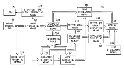
ing means 300 comprises a study mode processing means 302, a
practice mode processing means 304, a self-teaching mode
processing means 306, a first conversation mode processing
means 308, and a second conversation mode processing means
310 for the various modes described above.
As shown in FIG. 14, the study mode processing means
302 comprises an input processing means 320 for instructing
the LED 190 to emit light in response to the inputting of a
code by the user, a light-emitting signal generating means
322 for generating and outputting a light-emitting signal to
the LED 190 according to a turn-on or turn-off instruction
from the input processing means 320, and a character con-
verting means 324 for converting code information based on a
code entered by the user into character information.
The input processing means 320 outputs a turn-on or
turn-off signal depending on how the decision button 86 of
the manual control pad 88 is operated, and instructs the LED
190 to emit light or turn off light depending on how the de-
vision button 86 is operated. The character converting
means 324 samples a turn-on or turn-off signal from the in-
CA 02363715 2001-08-14
WO 01/43842 PCT/JP00/08821
- 27 -
put processing means 320, converts the signal into code in-
formation comprising a combination of dots and dashes, and
converts code information into character information.
The study mode processing means 302 also comprises a
list displaying means 326 for displaying a character list
204 (see FIG. 8B) on the display unit 90, a coordinate re-
ceiving means 328 for receiving positional information (co-
ordinates) of the cursor 206 at the time the decision button
86 is operated while the character list 204 is being dis-
played, a character retrieving means 332 for retrieving
character information from an information table 330 based on
the received coordinates, and a code retrieving means 334
for retrieving code information corresponding to the re-
trieved character information from the information table
330. The character information retrieved by the character
retrieving means 332 is stored in a reference character mem-
ory 336.
The study mode processing means 302 also comprises a
character displaying means 338 for displaying the character
information stored in the reference character memory 336 in
the character display area 200 of the display unit 90, a
code displaying means 340 for displaying the retrieved code
information as a combination of dots and dashes in the code
display area 202 of the display unit 90, a determining means
342 for determining whether the character information from
the character converting means 324 matches the character in-
formation stored in the reference character memory 336 or
CA 02363715 2001-08-14
WO 01/43842 PCT/JP00/08821
- 28 -
not, and a determined result displaying means 344 for dis-
playing a determined result from the determining means 342
on the display unit,90. The determining means 342 also de-
termines whether error information is outputted from the
character converting means 324 or not.
As shown in FIG. 15, the information table 330 stores a
plurality of records each containing character information
and code information. The character information represents
a Japanese character or a European character in the form of
a JIS code. The code information represents a Morse code
corresponding to the character information and comprising a
combination of logic data "10" and "11".
The logic data "10" represents a dot (~), and the logic
data "11" represents a dash (-). For example, since the
Morse code corresponding to the character "A" is "~-", the
code information "1011" is stored in association with the
character "A".
A processing sequence of the input processing means 320
will be described below with reference to FIG. 16. In step
S1 shown in FIG. 16, the input processing means 320 deter-
mines whether there is an input from the decision button 86
or not. If there is an input from the decision button 86,
then control goes to step S2 in which the input processing
means 320 gives a turn-on instruction to the light-emitting
signal generating means 322. The input processing means 320
then outputs a turn-on signal in step S3.
If there is no input from the decision button 86 in
CA 02363715 2001-08-14
WO 01/43842 PCT/JP00/08821
- 29 -
step S1, then control jumps to step S4 in which the input
processing means 320 gives a turn-off instruction to the
light-emitting signal generating means 322. The input proc-
essing means 320 then outputs a turn-off signal in step S5.
In step S6, the input processing means 320 determines
whether there is a program end request for the input proc-
essing means 320 or not. If there is no program end re-
quest, then control goes back to step Sl to repeat the proc-
essing from step S1.
While the decision button 86 is being operated in the
processing in steps S1 - S6, the processing in steps S2, S3
is repeated to output a turn-on instruction and a turn-on
signal successively. While the decision button 86 is not
being operated in the processing in steps S1 - S6, the proc-
essing in steps S4, S5 is repeated to output a turn-off in-
struction and a turn-off signal successively.
If there is a program end request in step S6, then the
processing sequence of the input processing means 320 is put
to an end.
As shown in FIG. 17, the character converting means 324
comprises a sampling means 350 for sampling the outputting
period of a turn-on signal or a turn-off signal based on one
unit of Morse code, and counting units of a signal length in
which the decision button 86 is operated and units of blank
length in which the decision button 86 is not operated. The
count of the units of the signal length is stored in a first
counter 352, and the count of the units of the blank length
CA 02363715 2001-08-14
WO 01/43842 PCT/JP00/08821
- 30 -
is stored in a second counter 354.
The character converting means 324 also comprises a co-
de information storing means 358 for checking if the signal
from the input processing means 320 represents dot informa-
tion or dash information based on the count of the units of
the signal length which is stored in the first counter 352,
and storing the checked result into a buffer 356 in succes-
sive addresses, a determining means 360 for determining
whether there is data in the buffer 356 and whether a char-
acter is to be converted or not based on the count of the
units of the blank length which is stored in the second
counter 354, and a character retrieving means 362 for re-
trieving character information corresponding to the code in-
formation stored in the buffer 356 from the information ta-
ble 330.
If the code information storing means 358 finds dot in-
formation based on the count of the units of the signal
length, then the code information storing means 358 stores
the logic data "10" into the buffer 356. If the code infor-
mation storing means 358 finds dash information based on the
count of the units of the signal length, then the code in-
formation storing means 358 stores the logic data "11" into
the buffer 356.
The character retrieving means 362 outputs error infor-
mation rather than character information if no character in-
formation corresponding to the code information stored in
the buffer 356 is present in the information table 330.
CA 02363715 2001-08-14
WO 01/43842 PCT/JP00/08821
- 31 -
A processing sequence of the study mode processing
means 302 will be described below with reference to FIGS.
13, 18 through 21.
In step 5101 shown in FIG. 18, the list displaying
means 326 displays the character list 204 on, the display
unit 90, as shown in FIG. 8B.
In step S102, the study mode processing means 302 de-
termines whether a character is selected or not based on
whether there is an input from the decision button 86 or
not. If there is an input from the decision button 86, then
control goes to step 5103 in which the coordinate receiving
means 328 receives positional information (coordinates) of
the cursor 206 at the time the decision button 86 is oper-
ated.
In step 5104, the character retrieving means 332 re-
trieves character information from the information table 330
based on the received coordinates. Thereafter, in step
5105, the character retrieving means 332 stores the re-
trieved character information into the reference character
memory 336. In step 5106, the code retrieving means 334 re-
trieves code information corresponding to the retrieved
character information from the information table 330.
In step S107, the character displaying means 338 dis-
plays the character information stored in the reference
character memory 336 in the character display area 200 of
the display unit 90, as shown in FIG. 8A. In step 5108, the
code displaying means 340 displays the retrieved code infor-
CA 02363715 2001-08-14
WO 01/43842 PCT/JP00/08821
- 32 -
mation as a combination of dots and dashes in the code dis-
play area 202 of the display unit 90.
In step 5109 shown in FIG. 19, the study mode process-
ing means 302 determines whether there is a test request
from the user or not. If there is a test request from the
user, control then goes to step S110 in which the study mode
processing means 302 erases the Morse code currently dis-
played in the code display area 202 of the display unit 90.
Then, the character converting means 324 performs its own
processing sequence in step 5111.
The processing sequence of the character converting
means 324 is shown in FIGS. 20 and 21.
In step 5201 shown in FIG. 20, the character converting
means 324 initializes the buffer 356 (see FIG. 17). In step
5202, the sampling means 350 samples the outputting period
of a turn-off signal based on one unit of Morse code, and
stores the count of the units of the blank length into the
second counter 354.
In step S203, the determining means 360 determines
whether there is data in the buffer 356 or not. If there is
data in the buffer 356, then control goes to step 5204 in
which the determining means 360 determines whether a charac-
ter is to be converted or not based on whether or not the
count of the units of the blank length stored in the second
counter 354 is 3 or more.
If there is no data in the buffer 356 in step 5203 or
if the count of the units of the blank length stored in the
CA 02363715 2001-08-14
WO 01/43842 PCT/JP00/08821
- 33 -
second counter 354 is 2 or less in step 5204, then control
goes to step S205 in which the sampling means 350 samples
the outputting period of a turn-on signal based on one unit
of Morse code, and stores the count of the units of the sig-
nal length into the first counter 352.
In step 5206, the code information storing means 358
checks if the signal from the input processing means 320
represents dot information or dash information based on the
count of the units of the signal length which is stored in
the first counter 352. In step S207, the code information
storing means 358 stores the code information based on the
checked result into the buffer 356 in successive addresses.
For example, if the checked result indicates dot informa-
tion, then the logic data "10" is stored into the buffer
356, and if the checked result indicates dash information,
then the logic data "11" is stored into the buffer 356.
After the processing in step S207, control returns to
step 5202 to repeat the processing from step 5202.
If the count of the units of the blank length stored in
the second counter 354 is 3 or more in step S204, then con-
trol goes to step S208 show in FIG. 21 in which the charac-
ter retrieving means 362 reads the code information from the
buffer 356. Thereafter, in step 5209, the character re-
trieving means 362 retrieves character information corre-
sponding to the code information stored in the buffer 356
from the information table 330.
In step 5210, the character retrieving means 362 deter-
CA 02363715 2001-08-14
WO 01/43842 PCT/JP00/08821
- 34 -
mines whether character information corresponding to the co-
de information stored in the buffer 356 is present in the
information table 330 or not. If corresponding character
information is present in the information table 330, then
control goes to step 5211 in which the character retrieving
means 362 outputs the retrieved character information.
In step S212, the character converting means 324 deter-
mines whether the conversation mode is presently executed or
not. In the conversation mode, since a word 220 composed of
a plurality of characters, rather than a single character,
is processed, successive characters need to be converted.
Therefore, if the conversation mode is presently exe-
cuted, then control goes to step 5213 in which the determin-
ing means 360 determines whether a character relative to a
next input is to be converted or not based on whether or not
the count of the units of the blank length stored in the
second counter 354 is 6 or less.
If the count of the units of the blank length stored in
the second counter 354 is 6 or less, then control goes to
step 5214 in which the character converting means 324 ini-
tializes the buffer 356. Thereafter, control goes to step
S205 shown in FIG. 20.
If the conversation mode is not presently executed in
step 5212 or if the count of the units of the blank length
stored in the second counter 354 is 7 or more in step 5213,
then the processing sequence of the character converting
means 324 is put to an end.
CA 02363715 2001-08-14
WO 01/43842 PCT/JP00/08821
- 35 -
If corresponding character information is not present
in the information table 330 in step 5210, then control pro-
seeds to step 5215 in which the character retrieving means
362 outputs error information rather than character informa-
tion. Thereafter, the processing sequence of the character
converting means 324 is ended.
In the main routine shown in FIG. 19, the study mode
processing means 302 determines whether there is error in-
formation outputted from the character converting means 324
with respect to the character conversion or not in step
S112. If there is no error information outputted from the
character converting means 324 with respect to the character
conversion, then control goes to step 5113 in which the de-
termining means 342 determines whether the character infor-
mation from the character converting means 324 matches char-
aster information stored in the reference character memory
336, i.e., character information based on the code entered
by the user, or not. If the character information from the
character converting means 324 matches character information
stored in the reference character memory 336, then control
goes to step S114 in which the determined result displaying
means 344 displays "~", indicative of a match, in the entire
displayed view of the display unit 90, as shown in FIG. 9C.
If the character information from the character con-
verting means 324 does not match character information
stored in the reference character memory 336, then control
goes to step S115 in which the determined result displaying
CA 02363715 2001-08-14
WO 01/43842 PCT/JP00/08821
- 36 -
means 344 displays "x", indicative of a matching failure, in
the entire displayed view of the display unit 90, as shown
in FIG. 9B.
If there is error information outputted from the char-
acter converting means 324 with respect to the character
conversion in step S112, then control goes to step 5116 in
which the determined result displaying means 344 displays
"NG", indicative of no corresponding character, in the en-
tire displayed view of the display unit 90, as shown in FIG.
9A.
After the processing in either one of steps S114 - 5116
or if there is no test request from the user in step 5109,
control goes to step 5117 to determine whether there is a
program end request for the study mode processing means 302
or not.
If there is no program end request, then control goes
back to step S101 to repeat the processing from step S101.
If there is a program end request, then the processing se-
quence of the study mode processing means 302 comes to an
end.
The practice mode processing means 304 will be de-
scribed below with reference to FIGS. 22 and 23. Those
parts of the practice mode processing means 304 which are
identical to those shown in FIG. 14 are denoted by identical
reference numerals, and will not be described in detail be-
low.
As shown in FIG. 22, the practice mode processing means
CA 02363715 2001-08-14
WO 01/43842 PCT/JP00/08821
- 37 -
304 has the input processing means 320, the character con-
verting means 324, the determining means 342, the determined
result displaying means 344, the code retrieving means 334,
the code displaying means 340, and the character displaying
means 338, and also additionally has a character extracting
means 370 for randomly extracting character information from
the information table 330 and storing the extracted charac-
ter information into the reference character memory 336.
The determining means 342 determines whether the char-
acter information from the character converting means 324
matches the character information stored in the reference
character memory 336 or not, whether error information is
outputted from the character converting means 324 or not,
and whether the limit time has elapsed or not based on time
information from the RTC 148.
The code retrieving means 334 retrieves code informati-
on corresponding to the character information extracted by
the character extracting means 370 from the information ta-
ble 330.
A processing sequence of the practice mode processing
means 304 will be described below with reference to FIG. 23.
In step S301 shown in FIG. 23, the character extracting
means 370 randomly extracts character information from the
information table 330, and stores the extracted character
information into the reference character memory 336.
In step 5302, the code retrieving means 334 retrieves
code information corresponding to the retrieved character
CA 02363715 2001-08-14
WO 01/43842 PCT/JP00/08821
- 38 -
information from the information table 330. In step 5303,
the character displaying means 338 displays the character
information stored in the reference character memory 336 in
the reference display area 208 of the display unit 90, as
shown in FIG. 10. In step 5304, the code displaying means
340 displays the retrieved code information as a combination
of dots and dashes in the reference display area 208 of the
display unit 90.
In step 5305, the character converting means 324 per-
forms its own processing sequence. Since the processing se-
quence of the character converting means 324 has already
been described above, it will not be described in detail be-
low. At this stage, however, the user enters a code as a
combination of dots and dashes, and the input display area
214 of the display unit 90 displays the code entered by the
user, with the LED 190 emitting light depending on the en-
tered code.
In step S306, the determining means 342 determines
whether the user has entered the code within the limit time
or not. If the user has entered the code within the limit
time, then control goes to step 5307 in which the determin-
ing means 342 determines whether the character information
from the character converting means 324, i.e., the character
information based on the code entered by the user, matches
the character information stored in the reference character
memory 336 or not. If the character information from the
character converting means 324 matches the character infor-
CA 02363715 2001-08-14
WO 01/43842 PCT/JP00/08821
- 39 -
mation stored in the reference character memory 336, then
control goes to step 5308 in which the determined result
displaying means 344 displays "~", indicative of a match, in
the entire displayed view of the display unit 90, as shown
in FIG. 9C.
If the character information from the character con-
verting means 324 does not match the character information
stored in the reference character memory 336 in step 5307,
if error information is outputted from the character con-
verting means 324, or if the limit time has elapsed in step
5306, then control goes to step S309 in which the determined
result displaying means 344 displays "x", indicative of a
matching failure, in the entire displayed view. of the dis-
play unit 90, as shown in FIG. 9B.
After the processing in step 5308 or 5309, control goes
to step S310 to determine whether there is a program end re-
quest for the practice mode processing means 304 or not.
If there is no program end request, then control goes
back to step S301 to repeat the processing from step 5301.
If there is a program end request, then the processing se-
quence of the practice mode processing means 304 is put to
an end.
The self-teaching mode processing means 306 will be de-
scribed below with reference to FIGS. 24 and 25. Those
parts of the self-teaching mode processing means 306 which
are identical to those shown in FIG. 14 are denoted by iden-
tical reference numerals, and will not be described in de-
CA 02363715 2001-08-14
WO 01/43842 PCT/JP00/08821
- 40 -
tail below.
As shown in FIG. 24, the self-teaching mode processing
means 306 has the input processing means 320, the character
converting means 324, the determining means 342, the charac-
ter displaying means 338, and the determined result display-
ing means 344. In the self-teaching mode, the determining
means 342 determines whether error information is outputted
from the character converting means 324 or not.
In the self-teaching mode processing means 306, the
character converting means 324 and the character displaying
means 338 jointly serve as a character converting and dis-
playing means.
A processing sequence of the self-teaching mode proc-
essing means 306 will be described below with reference to
FIG. 25.
In step 5401 shown in FIG. 25, the character converting
means 324 performs its own processing sequence. Since the
processing sequence of the character converting means 324
has already been described above, it will not be described
in detail below. At this stage, however, the user enters a
code as a combination of dots and dashes, and the input dis-
play area 214 of the display unit 90 displays the code en-
tered by the user, as shown in FIG. 11, with the LED 190
emitting light depending on the entered code.
In step 5402, the self-teaching mode processing means
306 determines whether there is error information outputted
from the character converting means 324 with respect to the
CA 02363715 2001-08-14
WO 01/43842 PCT/JP00/08821
- 41 -
character conversion or not. If there is no error informa-
tion outputted from the character converting means 324, then
control goes to step 5403 in which the character displaying
means 338 displays character information from the character
converting means 324 in the character display area 212 of
the display unit 90, as shown in FIG. 11.
If there is error information outputted from the char-
acter converting means 324 in step S402, then control goes
to step 5404 in which the determined result displaying means
344 displays "NG", indicative of no corresponding character,
in the entire displayed view of the display unit 90, as
shown in FIG. 9A.
After the processing in step 5403 or 5404, control goes
to step 5405 to determine whether there is a program end re-
quest for the self-teaching mode processing means 306 or
not.
If there is no program end request, then control goes
back to step S401 to repeat the processing from step 5401.
If there is a program end request, then the processing se-
quence of the self-teaching mode processing means 306 is put
to an end.
The first conversation mode processing means 308 will
be described below with reference to FIGS. 26 through 29.
Those parts of the first conversation mode processing means
308 which are identical to those shown in FIG. 14 are denot-
ed by identical reference numerals, and will not be de-
scribed in detail below.
CA 02363715 2001-08-14
WO 01/43842 PCT/JP00/08821
- 42 -
As shown in FIG. 26, the first conversation mode proc-
essing means 308 comprises a transmitter 380 and a receiver
382.
The transmitter 380 has the list displaying means 326,
the coordinate receiving means 328, and the character dis-
playing means 338.
The transmitter 380 also comprises a character/code re-
trieving means 384 for retrieving character information and
code information corresponding thereto from the information
table 330 based on received coordinates, a character/code
storing means 388 for successively storing the character in-
formation and the code information from the character/code
retrieving means 384 into a transmitting buffer 386, an LED
processing means 390 for giving an instruction to the light-
emitting signal generating means 322 to enable the LED 190
to emit light depending on a combination of dots and dashes
corresponding to a plurality of items of code information
among the character information and the code information
stored in the transmitting buffer 386, and a transmitting
means 392 for reading word/phrase information composed of a
plurality of items of character information among the char-
acter information and the code information stored in the
transmitting buffer 386, and transmitting the read
word/phrase information via the infrared emitter 162 to an
external device.
The receiver 382 comprises a receiving means 402 for
storing word/phrase information received via the infrared
CA 02363715 2001-08-14
WO 01/43842 PCT/JP00/08821
- 43 -
detector 164 into a receiving buffer 400, and a word/ phrase
displaying means 404 for reading word/phrase information
stored in the receiving buffer 400 and displaying the read
word/phrase information on the display unit 90.
A processing sequence of the transmitter 380 of the
first conversation mode processing means 308 will be de-
scribed below with reference to FIGS. 26, 27 and 28.
In step 5501 shown in FIG. 27, the list displaying
means 326 displays the character list 204 on the display
unit 90, as shown in FIG. 8B.
In step 5502, the transmitter 380 determines whether a
character is selected or not based on whether there is an
input from the decision button 86 or not. If there is an
input from the decision button 86, then control goes to step
5503 in which the coordinate receiving means 328 receives
positional information (coordinates) of the cursor 206 at
the time the decision button 86 is operated.
In step S504, the character/code retrieving means 384
retrieves character information and code information corre-
sponding thereto from the information table 330 based on the
received coordinates. In step S505, the character display-
ing means 338 displays the retrieved character information
on the display unit 90.
In step 5506, the character/code storing means 388 suc-
cessively stores the retrieved character information and the
code information corresponding thereto into the transmitting
buffer 386.
CA 02363715 2001-08-14
WO 01/43842 PCT/JP00/08821
- 44 -
In step 5507, the transmitter 380 determines whether
there is a transmitting instruction or not. If there is no
transmitting instruction, then control goes back to step
5501 to process next inputted character information. If
there is a transmitting instruction, then control goes to
step S508 in which the transmitting means 392 transmits a
plurality of items of character information (word/phrase in-
formation) stored in the transmitting buffer 386 to external
devices via the infrared emitter 162. The transmitted word/
phrase information is received by the receiver 382 of
another portable information terminal 18.
Thereafter, in step 5509, the LED processing means 390
performs its own processing sequence. The processing se-
quence of the LED processing means 390 is illustrated in
FIG. 28. In step 5601 shown in FIG. 28, the LED processing
means 390 successively reads a plurality of items of code
information from the items of character and code information
stored in the transmitting buffer 386. The read items of
code information are successively deleted from the transmit-
ting buffer 386.
In step 5602, the LED processing means 390 determines
whether there is data (code information) to be read or not.
If there is code information, then control goes to step S603
in which the LED processing means 390 determines whether the
read code information is relative to a dot or not based on
whether the read logic data is "10" or not.
If the read code information is relative to a dot, then
CA 02363715 2001-08-14
WO 01/43842 PCT/JP00/08821
- 45 -
control goes to step 5604 in which the LED processing means
390 gives an instruction (dot emitting instruction) to the
light-emitting signal generating means 322 to emit a dot of
light. In response to the dot emitting instruction from the
LED processing means 390, the light-emitting signal generat-
ing means 322 causes the LED 190 to emit light for a period
corresponding to one unit (dot light emission), for example.
If the read code information is relative to a dash in
step 5603, then control goes to step S605 in which the LED
processing means 390 gives an instruction (dash emitting in-
struction) to the light-emitting signal generating means 322
to emit a dash of light. In response to the dash emitting
instruction from the LED processing means 390, the light-
emitting signal generating means 322 causes the LED 190 to
emit light for a period corresponding to three units (dash
light emission), for example.
After the processing in step 5604 or 5605, control goes
to step S606 in which the LED processing means 390 sets a
blank length corresponding to two units between codes that
make up one character, and sets a blank length corresponding
to seven units between a plurality of characters. In this
manner, a blank of two units in which the LED 190 is turned
off is placed between codes that make up one character, and
a blank length corresponding to seven units is placed be-
tween a plurality of characters.
Thereafter, control returns to step S601 to repeat the
processing from the step 5601. If there is no code informa-
CA 02363715 2001-08-14
WO 01/43842 PCT/JP00/08821
- 46 -
tion to be read in step 5602, the processing sequence of the
LED processing means 390 is ended.
Control goes back to the routine shown in FIG. 27. In
step S510, the transmitting buffer 386 is initialized, and
the processing sequence of the transmitter 380 is put to an
end.
A processing sequence of the receiver 382 of the first
conversation mode processing means 308 will be described be-
low with reference to FIG. 29.
In step 5701 shown in FIG. 29, the receiving means 402
stores word/phrase information received via the infrared de-
tector 164 into the receiving buffer 400.
In step 5702, as shown in FIG. 12, the word/phrase dis-
playing means 404 displays the word/phrase information
stored in the receiving buffer 400 on the display unit 90.
After the processing in step S702, the processing sequence
of the receiver 382 comes to an end.
The second conversation mode processing means 310 will
be described below with reference to FIG. 30. As shown in
FIG. 30, the second conversation mode processing means 310
comprises a transmitter 380 and a receiver 382. The trans-
mitter 380 of the second conversation mode processing means
310 has the input processing means 320, the character con-
verting means 324, the determining means 342, the character
displaying means 338, the character/code storing means 388,
the transmitting means 392, and the LED processing means
390. At the time the determining means 342 determines that
CA 02363715 2001-08-14
WO 01/43842 PCT/JP00/08821
- 47 -
there is character information, the character displaying
means 338 displays the character information on the display
unit 90.
The receiver 382 of the second conversation mode proc-
essing means 310 is identical to the receiver 382 of the
first conversation mode processing means 308, and will not
be described below.
A processing sequence of the second conversation mode
processing means 310 will be described below with reference
to FIG. 31.
In step 5801 shown in FIG. 31, the character converting
means 324 performs its own processing sequence. Since the
processing sequence of the character converting means 324
has already been described above, it will not be described
in detail below. At this stage, however, the user enters a
code as a combination of dots and dashes, and the display
unit 90 displays the code entered by the user, with the LED
190 emitting light depending on the entered code.
In step 5802, the transmitter 380 determines whether
there is error information outputted from the character con-
verting means 324 with respect to the character conversion
or not. If there is error information outputted from the
character converting means 324, the character converting
means 324 performs its own processing sequence in step 5801.
At this time, the display unit 90 may display "NG". If
there is no error information, then control goes to step
5803 in which the character displaying means 338 displays
CA 02363715 2001-08-14
WO 01/43842 PCT/JP00/08821
- 48 -
character information from the character converting means
324 on the display unit 90.
In step S804, the character/code storing means 388
stores the character information and the code information
which have been retrieved in the transmitting buffer 386.
In step S805, the transmitter 380 determines whether
there is a transmitting instruction or not. If there is no
transmitting instruction, then control goes back to step
S801 to process next inputted character information. If
there is a transmitting instruction, then control goes to
step 5806 in which the transmitting means 392 transmits a
plurality of items of character information (word/phrase in-
formation) stored in the transmitting buffer 386 via the in-
frayed emitter 162. The transmitted word/phrase information
is received by the receiver 382 of another portable informa-
tion terminal 18.
In step 5807, the LED processing means 390 performs its
own processing sequence. The processing sequence of the LED
processing means 390 has already been described above, and
will not be described in detail below. In the processing
sequence of the LED processing means 390, the LED 190 emits
light representing a Morse code corresponding to the charac-
ter information to be transmitted.
In step 5808, the transmitting buffer 386 is initial-
ized. The processing sequence of the transmitter 380 of the
second conversation mode processing means 310 is now ended.
The processing sequence of the receiver 382 of the sec-
CA 02363715 2001-08-14
WO 01/43842 PCT/JP00/08821
- 49 -
and conversation mode processing means 310 is identical to
the processing sequence of the receiver 382 of the first
conversation mode processing means 308, and will not be de-
scribed below.
As described above, the portable information terminal
18 according to the present invention converts a Morse code
entered via the manual control pad 88 into character infor-
mation and displays the character information on the display
unit 90. Therefore, the portable information terminal 18
allows the user to generate characters with Morse codes.
The portable information terminal 18 can be used as a port-
able game machine, and can generate character information
with Morse codes and communicate with another portable in-
formation terminal 18 with the generated character informa-
tion.
Since the LED 190 is turned on in synchronism with the
inputting of a Morse code, the LED 190 emits light depending
on the inputting of the Morse code. Therefore, the user can
recognize the relationship between a Morse code and a char-
acter based on a visual sensation such as of light emission
as well as the inputting of the Morse code. The emission of
light from the LED 190 is effective to assist the user in
memorizing Morse codes, for example.
Inasmuch as character information entered via the manu-
al control pad 88 is converted into a Morse code, the port-
able information terminal 18 is suitable for use in communi-
cations with external devices using Morse codes. Further-
CA 02363715 2001-08-14
WO 01/43842 PCT/JP00/08821
- 50 -
more, because the LED 190 emits lights depending on a con-
verted Morse code, the portable information terminal 18
makes it possible to perform optical communications using
Morse codes.
The portable information terminal 18 has the transmit-
ter 380 for transmitting character information via the in-
frayed emitter 162 and the receiver 382 for receiving char-
acter information via the infrared detector 164 and for dis-
playing the character information on the display unit 90.
Thus, the portable information terminal 18 is capable of
performing sending and receiving character information
through both optical communications using Morse codes and
wireless communications in a radio frequency range (RF
range) and an infrared range (IR range). The user finds it
interesting to use the portable information terminal 18 be-
cause it can simulate communications using Morse codes.
Although a certain preferred embodiment of the present
invention has been shown and described in detail, it should
be understood that various changes and modifications may be
made therein without departing from the scope of the append-
ed claims.