Note: Descriptions are shown in the official language in which they were submitted.
CA 02364037 2001-08-30
Translation of WO 00/51709 (PCT/EPOO/01801)
Cleaning Device
The invention relates to a device for cleaning a filter surface of
a filter element, through which liquid to be filtered flows during
a~iltration operation, by means of a pressurized cleaning fluid.
Such devices are, for example, required for cleaning dust filters
used in industrial facilities. The dust filters used for
industrial purposes are in many cases approximately in the form of
a hollow cylinder wherein at one end of the filter elements an
outlet opening for the cleaned fluid such as, for example, flue gas
from which dust has been removed, is provided while a cylinder
mantle surface of the filter element is formed by a filter
substance such as a filter membrane or a filter fleece. This mantle
surface of the filter element then forms the filter surface through
which during the filtration operation the fluid to be cleaned, such
as flue gas, flows, wherein the dust particles contained in the
flue gas are retained by the filter substance in order to thus
provide the desired cleaning effect. In this connection, the fluid
to be cleaned impacts onto the outer surface of the filter element
and is then guided away through the hollow space formed by the
filter element or the outlet opening provided at one axial end of
the filter element.
During the above-mentioned filtration operation a filtration dust
cake is formed on the outer side of the filter element or of the
filter surface which increases with increasing operating duration
the flow resistance of the filter element for the fluid to be
1
CA 02364037 2001-08-30
i =
cleaned flowing therethrough. This increase of the flow resistance
causes a pressure loss of the fluid flow when passing through the
filter element which, in turn, impairs the discharge of the cleaned
fluid or makes it possible only by means of an expensive and high-
energy additional suction device.
Accordingly, the filter surfaces of the filter element must
generally be cleaned regularly in order to ensure a disturbance-
fxee operation in this way.
For this purpose, conventionally a pressurized cleaning fluid, such
as compressed air, is introduced through the outlet opening into
the interior of the filter in order to remove in this way the
filtration dust cake formed on the outer side of the filter element
or of the filter surface. However, it was found that filter
elements cleaned in this way again generate a high-pressure drop of
the fluid flow to be cleaned already after a comparatively short
operating period. As a solution to this problem it has been
suggested already to introduce the compressed air used as the
cleaning fluid in the form of individual compressed air pulses into
the interior of the filter element. Moreover, it has been
suggested to guide the cleaning fluid by means of nozzles into the
interior of the filter element wherein the nozzle openings of the
nozzles have a smaller diameter than the outlet opening of the
filter element in order to thus entrain, in addition to the
compressed air acting as the cleaning fluid, also ambient air into
the interior of the filter element and to increase the air volume
introduced into the filter element.
2
CA 02364037 2001-08-30
Even though with -the described measures an improvement of the
cleaning action of the cleaning fluid can be obtained, it was found
that even the introduction of the cleaning fluid into the interior
of the filter element in the form of individual pressure pulses
and/or by means of a suitable introduction nozzles, in comparison
to a disruption-free service life after the first initial start-up
of the filter element, a high-pressure loss of the fluid flow to be
cleaned occurred again already after a short operating period.
In view of these problems of the prior art, it is an object of the
invention to provide a device of the aforementioned kind which
makes possible a disruption-free operation as long as possible of
the filter element cleaned therewith.
According to the invention this object is solved by a further
development of the above discussed cleaning devices which is
substantially characterized in that a distribution device is
provided with which a substantially uniform pressure distribution
of the cleaning fluid in the area of the entire filter surface to
be cleaned is promoted.
The solution is based on the recognition that even the use of
suitable nozzles for introducing the cleaning fluid into the filter
element and the introduction of the cleaning fluid in the form of
individual pressure pulses result in a dynamic pressure of the
cleaning fluid in the area of the axial end of the filter element
facing away from the outlet opening which favors the cleaning
action of the filter surfaces in the area of the filter element
bottom but results in an incomplete cleaning of the filter surface
in the area of the outlet opening. Accordingly, when using the
3
CA 02364037 2001-08-30
known cleaning detrlices a satisfactory cleaning action takes place
only in the area immediately adjacent to the filter element bottom
of the filter surface. Because this area provides lowest flow
resistance for the fluid to be cleaned, the fluid flow will
concentrate in this area after a new start-up of the cleaned filter
element which again favors the formation of a filter cake
increasing the flow resistance so that very quickly a degree of
soiling requiring a new cleaning action of the filter element is
reached.
With the further development according to the invention of the
known cleaning devices, a uniform pressure distribution of the
cleaning fluid in the area of the entire filter surface to be
cleaned is achieved which results in a uniform cleaning of the
entire filter surface so that, in turn, the concentration of the
fluid flow during the filtration operation onto individual filter
surface segments is excluded. Accordingly, the use of the cleaning
device according to the invention can effectively prevent the fast
deposition of a filter cake on individual filter surface segments
and thus also an excessively fast increase of the flow resistance
of the filter element during filtration operation for a constant
fluid flow, and=the service life of the filter element can be
increased.
The uniform pressure distribution of the cleaning fluid can, for
example, be achieved by using a distribution device with a flow
guiding surface for the cleaning fluid exiting from a pressure
line. In this connection, on the one hand, the use of flow guiding
surfaces is possible with which a laminar flow of the cleaning
fluid is generated that ensures the desired uniform pressure
4
CA 02364037 2001-08-30
A
distribution. It is however especially advantageous when a
turbulent flow of the cleaning fluid flowing into the interior of
the filter element is.generated by the flow guiding surface because
such flow guiding surfaces can be embodied in a particularly simple
design that is however very effective. For this purpose, the
distribution device has expediently a distribution element that can
be inserted into an opening of the filter element providing'a
discharge for the fluid to be cleaned during the filtration
operation. Such a distribution element can be inserted for the
cleaning process into the filter element and can be removed again
from the filter element for performing the actual filtration
process. in addition, the use of distribution elements which
remain during the filtration operation in the filter element, for
example, in the form of a component that is fixedly connected to
the filter element, is however also considered. For example, the
distribution element can extend, beginning at the opening arranged
at one axial end of the filter element, into the interior of the
filter element which is at least substantially delimited by the
preferably cylinder mantle-shaped cylinder mantle surface. With
this arrangement, a particularly space-saving complete
configuration is made possible, in particular, in the case of a
distribution element remaining in the filter element during the
filtration operation.
The turbulent flow of the cleaning fluid introduced through the
opening of the filter element, which turbulent flow effects the
desired uniform pressure distribution of the cleaning fluid, can
be realized, while simultaneously ensuring a minimal flow
resistance during the filtration operation, in an especially simple
way when the distribution element has a flow guiding surface that
CA 02364037 2001-08-30
is cylinder mantle-shaped or truncated cone-shaped and extends
coaxially to the substantially cylinder mantle-shaped filter
surface. For this purpose, the distribution element is preferably
as a whole in the form of a cylinder mantle or a truncated cone
mantle. In this way, the desired uniform pressure distribution of
the cleaning fluid during the cleaning process can be ensured while
ensuring at the same time an especially minimal increase of the
flow resistance during the filtration operation when the
distribution element beginning at the opening extends across 20 to
70 %, preferably 20 to 50 %, of the axial length of the filter
element and the diameter of the distribution element at the end
facing away from the opening corresponds to approximately 40 to 95
% of the inner diameter of the filter element. At its end facing
the opening of the filter element, the distribution element can
have a diameter which corresponds to the inner diameter of the
filter element or the opening or can have a diameter which is
slightly smaller. In the case that for introduction of the
cleaning fluid a nozzle is used, it has been found to be
particularly expedient when the distribution element has a diameter
at the end facing the opening of the filter element which
aorresponds to the diameter of the nozzle or has a diameter which
is slightly greater than the diameter of the nozzle.
In the afore describe embodiment of the distribution element, an
especially minimal flow resistance during the filtration operation
can be achieved while simultaneously ensuring the desired uniform
pressure distribution of the cleaning fluid during the cleaning
process, when the dimensions of the distribution element are
adjusted such to those of the filter element that the ratio of flow
velocity of the fluid within the distribution element, flowing
6
CA 02364037 2001-08-30
through the filter surface during the filtration operation and
being discharged through the distribution element inserted into the
opening of the filter element, relative to the flow velocity of the
fluid external to the distribution element, flowing through the
axial area of the filter surface surrounding the distribution
element, is in the raage of 0.4 to 2.5. Accordingly, on the one
hand, the generation of a high dynamic pressure in the annular gap
formed between the distribution element and the filter surface in
the interior of the filter element is prevented and, on the other
hand, the generation of an excessive dynamic pressure within the
distribution element itself is prevented.
In addition or as an alternative to the above described
distribution element, the distribution device according to the
invention can also have a discharge element for the pressurized
cleaning fluid comprising a plurality of discharge openings through
which the cleaning fluid for cleaning the filter surfaces supplied
via a supply line is discharged or introduced into the interior of
the filter element for cleaning the filter element. This embodiment
of the device according to the invention is based on the
recognition that the use of several discharge openings for the
cleaning fluid in general provides a more effective cleaning pulse
than.the use of only one large discharge opening'for the cleaning
fluid.
In particular in regard to the last-described embodiment it has
been found to be especially expedient when the cleaning device has
a line system for the cleaning fluid with which a plurality of
filter elements can be cleaned simultaneously. In this connection,
expediently at least two discharge elements for discharging the
7
CA 02364037 2005-02-08
cleaning fluid for'cleaning a filter surface of a filter element,
respectively, are correlated with the line system wherein an
especially uniform cleaning effect for all filter elements to be
cleaned by one cleaning process is achieved when the discharge
element through which the cleaning fluid supplied by the cleaning
system passes first has more discharge openings than the discharge
element arranged downstream thereof. The advantage of this
arrangement resides in that the cleaning action, favored by the
dynamic pressure which is generated at the rear end of the line
system, for the filter elements arranged in this area during the
cleaning process can be compensated by providing more discharge
openings for the filter elements arranged during the cleaning
process in the area of the forward end of the line system when
viewed in the flow direction.
In the case that the cleaning fluid for cleaning the filter
surfaces is to be discharged in the form of individual pressure
pulses, such as gas pressure pulses, in particular, compressed air
pulses, it was found to be particularly expedient when the line
system has only one valve arrangement for generating the pressure
pulses and the individual discharge elements are arranged at the
outflow side of this valve arrangement. In this connection, it is
in particular also considered to discharge the cleaning fluid
through a nozzle in the direction toward the filter surfaces or
interiors of the filters to be cleaned.
8
CA 02364037 2005-02-08
According to one aspect of the present invention there is
provided an arrangement comprising a filter element and a
device for cleaning a substantially cylinder mantle-shaped
filter surface of a filter element, through which a fluid
to be cleaned flows during filtration operation, by means
of a pressurized cleaning fluid, wherein a distribution
device having a flow guiding surface for the cleaning fluid
exiting from a pressure line is provided, with which a
substantially uniform pressure distribution of the cleaning
fluid in the area of the entire filter' surface to be
cleaned is promoted, wherein the flow guiding surface
extends coaxially to the filter surface, is as a whole
substantially truncated cone mantle-shaped, and extends,
beginning at an opening arranged at an axial end of the
filter element, across 20 to 70% of the axial length of the
filter element.
According to another aspect of the present invention there
is provided an arrangement comprising a filter element and
a device for cleaning a substantially cylinder mantle-
shaped filter surface of a filter element, through which a
fluid to be cleaned flows during filtration operation, by
means of a pressurized cleaning fluid, wherein a
distribution device having a flow guiding surface for the
cleaning fluid exiting from a pressure line is provided,
with which a substantially uniform pressure distribution of
the cleaning fluid in the area of the entire filter surface
to be cleaned is promoted, wherein the flow guiding surface
extends coaxially to the filter surface, is as a whole
substantially truncated cone mantle-shaped, and extends,
beginning at an opening arranged at an axial end of the
filter element, across 20 to 70% of the axial length of the
filter element, while the diameter of the distribution
8a
CA 02364037 2005-02-08
element at its end facing away from the opening corresponds
approximately to 40 to 95% of the inner diameter of the
filter element.
In the following the invention will be explained
with reference to the drawing to which express
reference is being had with respect to all details that are
important in regard to the invention and not explained
in greater detail in the description. In the single
8b
CA 02364037 2005-02-08
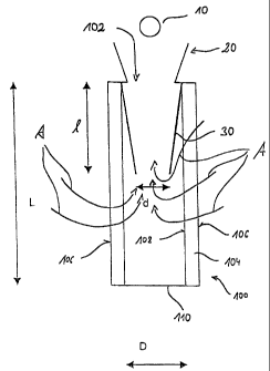
figure of the drawing a cleaning device according to an
embodiment of the invention is schematically illustrated.
The cleaning device illustrated in the drawing is comprised
substantially of a line system 10, such as a compressed air line
and having a discharge opening for the cleaning fluid; a nozzle 20
through which the cleaning fluid, such as compressed air, can be
discharged into the interior of a filter element which in its
entirety is referenced by 100; and a distribution element 30
inserted into an opening 102 of the filter element forming during
the filtration operation of the filter element 100 a discharge for
the cleaned fluid.
The filter element 100 to be cleaned with the cleaning device
illustrated in the drawing has substantially the shape of a hollow
cylinder wherein the outlet opening 102 is arranged at one axial
end of the filter element while the cylinder mantle surface 106 is
formed by a filter material 104 such as, for example, a filter
membrane or a filter fleece. At the end opposite the outlet
opening the filter element 100 is closed off by a bottom 110_
During normal filtration operation the fluid to be cleaned flows
through the filter material 104 and is discharged from the filter
element 100 by the distribution element 30 introduced into the
outlet opening as illustrated in the drawing by arrows A. In this
connection, the dust entrained by the fluid to be cleaned is
deposited on the exterior surface 106 of the filter material 104.
For cleaning the filter surface formed by the exterior surface 106
of the filter material 104, by means of the line system 10
9
CA 02364037 2001-08-30
compressed air is introduced through the nozzle 20 and the
distribution element 30 into the interior of the filter element
10o, In this connection, by means of the distribution element 30
a turbulent flow of the introduced cleaning fluid is generated in
the interior of the filter which results in a uniform pressure
distribution of the cleaning fluid in the area of the entire filter
surface 106 to be cleaned. For this purpose, the distribution
element 30 is in the form of a truncated cone mantle which extends,
starting at the outlet opening 102 in the direction toward the
bottom 110, coaxially to the cylinder mantle-shaped exterior
surface 106 of the filter material 104. The axial length 1 of the
distribution element 30 corresponds in this connection
approximately to 40 $ of the axial length L of the filter element
100. The diameter of the distribution element 30 corresponds at
the end of the distribution element 30 facing the outlet opening
102 to the inner diameter D of the filter element 100. In the
direction toward the bottom 110 of the filter element 100, the
distribution element 30 tapers to a diameter d which is
approximately 56 % of the inner diameter D of the filter element
100.
For ensuring a disruption-free introduction of the cleaning fluid,
the distribution element 30 at its end facing the outlet opening is
provided with a smooth and rounded edge. On the other hand, the
discharge element 30, at the end facing the bottom 110, is provided
with a smooth cut edge for ensuring the desired turbulent flow of
the cleaning fluid introduced through the nozzle 20 within the
filter element 100. As can be seen in the drawing, in connection
with the distribution element 30 inserted into the filter element
100, a nozzle 20 is expediently used whose diameter at the end
CA 02364037 2001-08-30
facing the filter 'element 100 is smaller than the diameter of the
distribution element 30 at its end facing the outlet opening.
With the described adjustment of the dimensions of the distribution
element 30 to the dimensions of the filter element 100 it is
ensured that the ratio of the velocity of the fluid within the
distribution element 30 flowing through the filter material 104
during normal filtration operation to the velocity of the fluid
flowing through the filter material 104 in the annul.ar gap formed
between the outer boundary surface of the distribution element 30
and the inner boundary surface 108 of the filter element 104 is in
the range of 0.4 to 2.5 so that during the filtration operation a
reduced flow resistance of the filter element is ensured, even when
the distribution element 30 during filtration operation remains
within the interior of the filter element ].00.
The invention is not limited to the embodiment illustrated in
connection with the drawing. In addition, it is also considered to
employ, for maintaining a uniform pressure distribution of the
cleaning fluid in the area of'the entire filter surface to be
cleaned, a discharge element with a plurality of discharge openings
for discharging the cleaning fluid. Moreover, instead of the
truncated cone mantle-shaped distribution element, a cylinder
mantle-shaped distribution element can be used. Moreover, instead
of the distribution element secured in the area of the inner rim of
the outlet opening a distribution element can be used which engages
across the axial end of the filter element 100.
11