Note: Descriptions are shown in the official language in which they were submitted.
CA 02364079 2001-12-05
Patent Application
of
Samuel Bock
for a
Weighted Footwear Insert
Field of the invention:
The present invention relates to the general field of footwear accessories and
is
particularly concerned with a weighted footwear insert.
Background of the invention:
The efficiency of weights for improving muscle strength and tone is well
established.
Athletes in particular, for example, have long been training with weights
mounted on the
lower limbs in order to develop muscles for running, jumping and the like. Non-
athletes
can also benefit from such training aids by merely incorporating the use of
the training
aids in their daily regimens of moving about. Repeated use of such lower limb
mounted
weights when active can lead to strengthening of the leg muscles, increase in
cardiovascular capacity and a generally higher metabolic rate. It is also
believed that
rehabilitative efforts might be hastened and improved with specific training
of locally
mounted weights.
The prior art is replete with various types of structures for adding weight to
the lower
limbs of intended users. One particularly popular method of adding weight to
the lower
limbs makes use of conventional ankle weights, including a strap configured
and sized
for mounting around the ankles, and having weights attached thereto. Apart
from being
most uncomfortable, one of the drawbacks associated with conventional ankle
weights is
that the ankle takes too much shock with each step or stride when the weight
is placed
around the ankle, as the ankle itself is what stops the mass of the weight
from
accelerating to the ground with each step. This causes the weight to jam the
ankle with
each step, leading to stretched ligaments and sore tendons after several weeks
of use.
1
CA 02364079 2001-12-05
The intended mass needs to be below the foot if the body is to be prevented
from
decelerating the mass with each step. If the mass is below the foot, the
ground the foot
is striking stops the mass instead, eliminating shock to the body.
The solution to eliminating shock from weight placed above the ankle is to
attach or
incorporate the weight to the footwear. This solution has been recognised in
the prior
art. Indeed, some prior art patents disclose footwear incorporating weighted
elements.
For example, US patent 4,458,433 issued July 10'", 1984 and naming Frank
Stempski
as inventor discloses a footwear having a weight pocket at the outside of a
toe region of
the upper structure for receiving removable weights therein. The structure
also proposes
optional heel and side pockets for additional weights. The structure disclosed
in US
patent 4,448,432 however has major flaws including that positioning of the
weight above
the sole of the foot tends to create awkward muscle development. The disclosed
structure also makes it difficult to prevent the weighted mass from moving
around under
heavy accelerations.
US patent 5,231,776 issued August 3'd, 1993 naming Rodger D. Wagner as
inventor
discloses a footwear incorporating a grid matrix which is moulded into the
footwear and
sandwiched between the inner and outer sole of the latter. Relatively small
weighted
spheres typically of less than 1 mm of diameter are inserted into the lattice
grid matrix.
Although presenting a somewhat elegant solution to the problem of weight
distribution,
the structure disclosed in the US patent 5,231,776 suffers from the fact that
the weight is
permanently fixed into the shoe. The structure thus lacks in versatility and
transferability
between shoes.
US patent 3,517,928 discloses a weighted shoe using a weight receiving member
frame
inside the shoe, the weight receiving member frame being coextensive with the
sole.
The weight-receiving frame is permanently built into the shoe and has openings
for
receiving different weight plugs. One of the main disadvantages associated
with this
device is that a favourite or expensive shoe would need to be permanently
altered to
properly incorporate the member frame according to the disclosure.
2
CA 02364079 2001-12-05
US patent 4,252,315 issued February 24'", 1981 naming Akira Kimura as inventor
discloses a training aid including a toe portion and a heel portion with both
having a core
member made of heavy metal and a resilient covering member surrounding the
core
member. The toe and heel portions are so shaped that they form substantially a
sole
S configuration when they are placed side by side on the sole of a shoe.
One of the main drawbacks associated with the structure disclosed in US patent
4,252,315 relates to the lack of flexibility of the core members which leads
to discomfort
and potential injury to the wearer since the core members are unable to
conform to the
wearer's foot contour especially during motion.
The problem of weighted insoles having insufficient flexibility and being
unable to
conform to the changing configuration of a foot during motion has been
recognized in the
prior art. Attempts have been made to at least partially solve the problem.
For example,
1 S US patent 4,709,921 naming Antonette G. Valuikas and Ralph Valuikas as
inventors and
issued December 1St, 1987, as well as US patent 5,638,613 naming James H.
Williams
and issued June 1 T", 1997, both specifically address the lack of flexibility
issue.
US patent 4,709,921 discloses a weighted shoe insert having a weighted base
member
formed either as an integral portion of a shoe, or as a discrete insert
sandwiched
between an upper adhesively backed cover and a lower adhesively backed cover.
The
base member contains a series of perforation and edge contours which
facilitate the
shaping of the base member to conform with the shape of a human foot. In a
second
preferred embodiment, the base member is composed of a series of discrete
elements in
which chafing between adjacent segments has been substantially reduced by the
contouring of the edges.
US patent 5,638,613 discloses a weighted insole having a pair of flat weights
encapsulated inside a flexible material, which is formed into an insole for
placement in a
shoe. A first weight is encapsulated in front and a second weight is
encapsulated behind
the ball of the foot area. The second weight additionally has cutouts at the
arch and heel
areas of the foot.
3
CA 02364079 2001-12-05
These unweighted areas throughout their thicknesses include insole materials
that
provide extra comfort and cushioning where the user typically places more
weight on the
foot. The front and back weighted construction additionally allows for
flexibility of the
insole at the ball area. A pattern of nodes is projected from the bottom of
the insole to
S frictionally hold the insole in place in the shoe.
Although US patents 4,252,315, 4,709,921 and 5,638,613 recognize the need for
a
flexible sole they still disclose structures presenting inherent major
drawbacks that are
not taking into account the relative complexity of the human foot and the
knowledge
emanating from the field of advanced athlete training and rehabilitation. In
order to fully
understand the problems associated with prior art structures and the
advantages
associated with the present invention a basic knowledge of foot anatomy is
required.
The foot and ankle combine flexibility with stability because of the many
bones they
comprise and because of their shapes. The lower leg, ankle and foot have two
principle
functions, mainly propulsion and support. For propulsion, they act like a
flexible lever.
For support, they act like a rigid structure that holds up the entire body.
The foot
performs several important functions such as acting as a support base that
provides the
necessary stability for upright posture with minimal muscle effort, providing
a mechanism
for rotation of the tibia and fibula during the stance phase of gait,
providing flexibility to
adapt to uneven terrain, providing flexibility for absorption of shock by
becoming a rigid
structure in the pronated position and acting as a lever during "push-off'.
The joints of the lower leg, ankle and foot act as functional groups not as
isolated joints.
The movement occurring at each individual joint is minimal. However, when
combined,
there normally is sufficient range of motion in all of the joints to allow
functional mobility
as well as functional stability. A suitable insole structure thus must take
into account the
movements occurring at each individual joint, however minimal. In particular,
a suitable
insole structure must take into account the movements occurring at each
individual joint
not only the movements leading to a flexing of the foot about a generally
transversally
oriented pivotal axis but also at the joints leading to flexing of the foot
about a generally
longitudinal pivotal axis orientation or a combination of both longitudinal
and transversal
orientation.
4
CA 02364079 2001-12-05
For ease of understanding, the joints of the foot are divided into three
sections namely
hind-foot or tarsus, the mid-foot or mid-tarsus, and the forefoot or
metatarsus. The hind-
foot contains two bones, the talus and the calcaneus. The joints of the hind-
foot are the
tibiofibular joints. The interior or distal tibiofibular joint is a fibrous or
syndesmosis type
of joint. The movements at this joint are minimal but allow a small amount of
spread at
the ankle joint during dorsiflexion.
The talocrural joint, or ankle joint, is a uniaxial, modified hinge synovial
joint located
between the talus, the medial malleolus of the tibia and the lateral malleolus
of the fibula.
The talocrural joint is designed for stability, not mobility. The subtalar
joint is a synovial
joint having three degrees of freedom and a closed pack position of
supination. The
movements possible at the subtalar joints are gliding and rotation. In
addition, medial
rotation of the leg causes a valgus, or outward movement of the calcaneus.
Lateral
rotation of the leg produces a varus or inward movement of the calcaneus.
The mid-tarsal joints part of the mid-foot include the talocalcaneonavicular
joint, typically
a ball and socket and synovial joint with three degrees of freedom. Movements
possible
at this joint are gliding and rotation. The cuneonavicular joint is a plain
synovial joint. The
movements possible at this joint are sliding and rotation. The
cuboideonavicular joint is
fibrous. The movements possible at this joint are gliding and rotation.
The intercuneiform joints are plain synovial joints. The movements possible at
these
joints are slight gliding and rotation. The cuneocuboid joint is a plain
synovial joint. The
movements of slight gliding and rotation are possible at this joint. The
calcaneocuboid
joint is a saddle shape with a closed pack position of supination. The
movement possible
at this joint is gliding with conjunct rotation. The mid-foot contains the
three cuneiforms,
the navicular and the cuboid and is separated from the hind-foot by the
transverse mid-
tarsal joint of Chopart.
The forefoot contains the five metatarsals and fourteen phalanges. It is
separated from
the midfoot by the tarsometatarsal joint of Lisfranc. Joints of the forefoot
include the
torsometatarsal joints which are plain synovial joints offering possible
gliding movement.
They also include four intermetatarsal joints which are plain synovial joints
offering the
possibility of gliding motion. They further include five metatarsophalangeal
joints that
S
CA 02364079 2001-12-05
are condyloid synovial joints with two degrees of freedom. The movements
possible at
these joints are flexion, extension, abduction and adduction. The joints of
the forefoot
further include interphalangeal joints, which are synovial hinged joints with
one degree of
freedom. The movements possible at these joints are flexion and extension.
The structures disclosed in the prior art patents fail to properly account for
the possible
movements of the numerous joints of the human foot necessary to allow for the
proper
biomechanical functioning fit. For example, both US patents 4,252,315 and
5,638,613
assume that the mid and hind-foot are mostly static and that a relatively
solid piece of
material supporting both the mid and hind-foot will provide adequate support
during
motion. US patent 5,638,613 discloses the use of a material allowing for semi-
permanent forming in order to take into consideration the particular initial
configuration of
a static foot. However, it doesn't take into account that the sole of the foot
is constantly
changing in configuration during motion. The proposed semi-permanent design
does
not adapt to the foot's necessary freedom of movement and continual
configuration
change necessary for dynamic action found in athletic activity.
The typical foot active movements include plantar flexion of the ankle. During
plantar
flexion the heel of the foot will normally invert when the movement is
performed when in
weight bearing position. If heel inversion does not occur, the foot will be
unstable.
Dorsiflexion of the ankle or standing on the heels is usually 20 degrees past
the
anatomic position or when the foot is approximately at 90 degrees to bones of
the leg.
Supination or standing on the lateral edge of the foot and pronation or
standing on the
medial edge of the foot are respectively through ranges of 45 to 60 degrees
and 15 to 30
degrees although there is variability among individuals. Supination or inward
torsion
combines the movements inversion, adduction and plantar flexion. Pronation or
outward
torsion combines the movements of eversion, abduction and dorsiflexion of the
foot and
ankle. The prior art patents fail to disclose structures allowing for the
complete range of
possible movements. For example, the lack of lateral flexibility renders both
pronation
and supination virtually impossible.
6
CA 02364079 2001-12-05
In normal stance, the body weight is equally distributed between the heel and
ball of the
foot. Muscular contraction is necessary to maintain this normal balance. For
example,
with muscle relaxation, 80 percent of the weight loaded on the knee will be
distributed
onto the metatarsal and 20 percent on the calcaneus. In normal stance, the
contraction
of the triceps surae creates an equal weight distribution between the
metatarsal and the
calcaneus.
Weight distribution among the metatarsal also depends on muscle contraction.
In
normal stance, the one half body weight borne by the metatarsals is
distributed in the
ratio 2:1:1:1:1 from the medial to the lateral rays. That is, the first
metatarsal bears twice
the weight of any of the others and one third of the weight carried by the
forefoot or one
sixth of the body weight. Studies have shown that relatively small changes in
muscle
balance and tone can result in significant changes in the load distribution of
the foot.
Therefore, the load mechanism in the foot is far more than an aesthetic arch.
It depends
on normal function of the bones, ligaments and muscles acting in concert.
Another factor affecting weight distribution is the direction of thrust of the
tibia in standing
and especially in walking and running. Torque on the tibia has significant
effect on
loading. Internal torsion produces pronation and loads the first ray, while
external tibia)
torsion produces supination and loads the lateral rays. These loads, however,
can be
negated if muscles are contracted during loading. In walking, the weight is
shifted from
the heel to the ball of the foot in a straight line that parallels the line of
forward
progression. In a normal out-toeing gait, the weight moves from the lateral
calcaneus
and heel in a straight line forward to the head of the first metatarsal. In an
ingoing gait,
the heel strikes on the inner border of the heel and the weight moves towards
the lateral
metatarsal.
The structures disclosed in the prior art patents do not take into
consideration the
. complexity of the movements of the various joints and, hence, the changes in
the weight
distribution during motion. The use of a material providing semi-permanent
forming as
proposed by the US patent 5,638,613 and the use of an insole having only
transversal
perforations or transversally separated discrete elements as proposed by US
patent
4,709,921 simply do not account for variations in position and weight
distribution
occurring in the transversal direction during movement of the foot.
7
CA 02364079 2001-12-05
Furthermore, the prior art structure, by failing to take into consideration
the transversally
occurring phenomena, also failed to take into consideration the crucial role
of the
longitudinal arches of the foot for weight bearing. The arches of the foot are
maintained
by three mechanisms: wedging of the interlocking tarsal and metatarsal bones
takes
place; the ligaments on the plantar aspect of the foot play a significant
role; and the
intrinsic and extrinsic muscles of the foot and their tendons help to support
the arches.
The longitudinal arches form a cone as a result of the angle formed by the
metatarsal
bones with the floor. The medial longitudinal arch being more evident, this
angle is
greater on the medial side. The specific cone shaped configuration of the
longitudinal
arches simply cannot be matched by the structures proposed in the prior art
patents and,
hence, the proper arch support results from these structures.
The medial longitudinal arch consists of the calcaneal tuborisity, the taleas
and the
nevicular bone, three cuneiforms and first, second and third metatarsal bones.
The
calcaneus, cuboid forth and fifth metatarsal bones make up the lateral
longitudinal arch.
The transverse arch consists of the navicular bone, cuneiforms and cuboid and
metatarsal bones. The arch is sometimes divided into three parts, tarsal,
posterior
metatarsal and interior metatarsal. The loss of the interior metatarsal arch
results in
callous formation under the heads of the metatarsal bones. The metatarsal
joints are
slightly extended when the intended user is in the normal standing position
because the
longitudinal arches of the foot curve downward towards the toes. Normal arches
of the
foot hence play a crucial role for functional stability and mobility. Improper
support of the
arches may potentially lead to injury.
The fact that the prior art structures are not adapted to follow the changing
contour of the
sole of the feet in motion and to provide adequate arch support not only
potentially leads
to improper muscle development and potential injury, but it also actually
leads to
erroneous central nervous system adaptation which, in turn, may be detrimental
to the
performance of the athlete. Indeed, it has been shown that repeated training
of specific
biomechanical motions allows the establishment of motor memory between the
brain
and individual muscle cells through the central nervous system.
8
CA 02364079 2001-12-05
Unrelated motor activity associated with training muscles in matters that do
not use the
same biomechanical motion as used in competition can confuse the ability of
the brain to
establish the motor memory pathways necessary for the execution of specific
athletic
activities. One of the objectives of modern training is thus to train the
brain and body to
strengthen and learn a specific action in the least amount of time, with a
minimum of
other athletic activity which uses the brain and central nervous system in a
different
matter and which would potentially cause the brain to develop unrelated motor
memory
pathways.
In addition the biomechanical action of the muscle groups, the development of
chemical
energy generated by the cells of the muscle groups being used must also be
considered.
The rate of generation of chemical energy will differ with different levels of
expenditure.
Full speed activity uses exponentially more power than half or quarter speed
activity.
Individual muscle cells adapt only to the power level being repeatedly
trained.
Prior art structures are not well adapted to establishing proper motor memory
pathways,
since the lack of flexibility on the proposed weighted plate forces the
subject to use
different biomechanical parameters during training as compared to those used
during
actual competition, or other specific activities without the plates. The use
of training
equipment which forces the subject to alter normal motor memory and
biomechanical
sequences also impedes the ability of individual muscle cells to fully develop
energy
output for competition, or other specifically intended uses.
The full development of an individual cell's maximum energy output is only
possible if the
cell is consistently being used or trained in the correct motor memory
sequence.
Training individual muscle cells in a different manner has been shown to
primarily
develop the cells for that particular motor sequence only. Transfer of such
neuro
muscular conditioning to other motor actions has been shown to be less than
optimal.
This is why modern sport training techniques have become very motor specific
to the
training task at hand.
9
CA 02364079 2001-12-05
Another drawback associated with prior art structures is that since the prior
art insoles
are made out of relatively large segments attached to each other, the pressure
exerted
by the foot of the intended user is not transmitted proportionally to
corresponding areas
of the shoe structure but rather partially absorbed and redistributed to the
insole itself,
which has no shock absorbing capability as compared to the midsole of modern
training
footwear, significantly altering and reducing the shock absorption properties
of said
footwear. This, in turn, reduces the overall bio-mechanical efficiency of the
shoe-insole
combination.
Other drawbacks associated with prior art structures are related to these
specific types
of materials and overall configurations that have been selected. Indeed, the
structures
disclosed in US patent 4,709,921 and 5,638,613 are made of lead, a toxic
material,
which can potentially be absorbed by the human skin especially in the often
hot and
humid environment of a shoe during training.
Furthermore, the structures disclosed in US patent 4,709,921 and 5,638,613 are
relatively thick as compared with the structure of the proposed invention.
When these
relatively thick insoles are put in shoes that come with conventional modern
insole liners,
which are quite thin, they take up a relatively large volume, forcing the user
to buy an
extra pair of shoes to train. Indeed, most impact absorption in modern
training shoes is
provided by the advanced materials now found in the mid-soles of such footwear
and not
the insole itself. The modern insole that cover the stitching in the shoes
upper
construction is often very thin and differs in thickness and overall function
from one shoe
design to another. The relatively thick insoles proposed by US patents
4,709,921 and
5,638,613 are proportionally relatively thick relative to the insoles of
modern footwear.
Accordingly, there exists a need for an improved weighted footwear insert.
Advantages
of the present invention include that the proposed weighted footwear insert is
specifically
designed so as to follow the changing configuration of the sole of the feet of
an intended
user during motion.
CA 02364079 2001-12-05
The proposed weighted footwear insert is designed so as to take into account
variations
in configuration and weight distribution of a given foot sole section in a
transversal
direction. The improved flexibility of the proposed weighted footwear insert
allows the
latter to instantly and fully adapt to the mid-sole below and the insole above
of the
conventional shoe, thereby allowing full transfer of the footwear's cushioning
properties.
The proposed weighted footwear insert allows for adequate support of the foot
arches
while providing flexibility thus reducing risk of injury during training.
Furthermore, the proposed weighted footwear insert allows for the development
of
optimized motor memory pathways during training. The proposed weighted
footwear
insert is configured so as to be easily transferable between pieces of
footwear thus
reducing the need for buying multiple inserts.
Furthermore, the proposed weighted footwear insert is designed as to be
comfortable
and easily concealed within conventional footwear so as not to deter to the
overall
aesthetical aspect of the latter. Furthermore, the proposed weighted footwear
insert has
a generally thin configuration so as to obliviate the need for buying a shoe
of a larger
size in order to incorporate the weighted footwear insert in accordance with
the
invention.
Still further, the proposed weighted footwear insert is specifically designed
so as to
transmit the pressure exerted by the foot of the intended user directly to the
shoe
structure with reduced alteration of the pressure distribution on the shoe
structure so as
to maintain the overall biomechanical efficiency of the shoe-insole
combination.
The present invention also relates to a method for forming a weighted footwear
insert in
accordance with the present invention. The proposed method allows for
reformation of a
weighted footwear insert through a set of optimized steps that can be
performed with
conventional equipment and using conventional materials so as to allow for the
production of a weighted footwear insert that will be economical, long lasting
and
relatively trouble free in operation. The proposed method also allows for the
production
of customized weighted footwear inserts that are optimized for specific
individual
biomechanical parameters and training techniques.
11
CA 02364079 2001-12-05
In accordance with an embodiment of the present invention, there is provided a
weighted
footwear insert for use inside a footwear, the footwear being wearable by a
foot of an
intended user, the foot having a foot sole, the footwear including a generally
elongated insole, the insole defining an insole peripheral edge, an insole
longitudinal
axis and an insole transversal axis, the footwear insert comprising: a
weighted plate,
the weighted plate defining a plate first surface, a plate second surface, a
plate toe
end, a plate heel end, a plate peripheral edge, a plate longitudinal axis and
a plate
transversal axis, the weighted plate being configured and sized for insertion
into the
footwear with the plate longitudinal axis extending in a direction generally
parallel to
the insole longitudinal axis and the plate transversal axis extending in a
direction
generally parallel to the insole transversal axis; the weighted plate defining
a first pair
of plate segments, the plate segments defining a segment longitudinal fold
line
therebetween for allowing the plate segments to fold relative to one another
about
the segment longitudinal fold line; the segment longitudinal fold line
defining a
longitudinal fold line orientation axis, the longitudinal fold line
orientation axis defining
a longitudinal fold line-to-longitudinal axis angle between the longitudinal
fold line
orientation axis and the plate longitudinal axis, the longitudinal fold line
orientation
axis defining a longitudinal fold line-to-transversal axis angle between the
longitudinal fold line orientation axis and the plate transversal axis; the
longitudinal
fold line-to-longitudinal axis angle being smaller in value then the
longitudinal fold
line-to-transversal axis angle; the weighted plate also including a generally
transversally extending transversal bending means for allowing the weighted
plate to
bend along the transversal bending; whereby the longitudinal segment fold line
extends in a more longitudinal then transversal direction for allowing the
weighted
plate to substantially follow the transversal contour of the foot sole.
Preferably, the transversal bending means includes a segment transversal fold
line
extending between the first pair of plate segments and a second pair of plate
segments, both the first and the second pair of plate segments having their
respective plate segments separated by the segment longitudinal fold line.
Preferably, the transversal bending means includes a plurality of segment
transversal fold lines.
12
CA 02364079 2001-12-05
Conveniently, the plate segments are disposed relative to each other so as to
define a
segment spacing therebetween; the weighted footwear insert further comprising
a
flexible coupling means attached to adjacent plate segments for flexibly
coupling
adjacent plate segments together so as to allow bending therebetween about the
coupling means.
In one embodiment, the flexible coupling means includes a first flexible
membrane fixed
to the plate first surface on adjacent plate segments, the first flexible
membrane
extending across the segment spacing. Preferably, the flexible coupling means
also
includes a second flexible membrane fixed to the plate second surface on
adjacent
plate segments, the second flexible membrane also extending across the segment
spacing. In another embodiment, the flexible coupling means includes a
flexible web
of material extending integrally between adjacent plate segments.
Optionally, the coupling means allows bending between the plate segments
within a
predetermined limited bending range. Optionally, the first pair of plate
segment is
made of plate segments having different densities. Optionally, the first pair
of plate
segments is made of plate segments having different cross-sectional
configurations.
Optionally, the segment longitudinal fold line extends across the weighted
plate from
the plate toe end to the plate heel end.
In accordance with one embodiment of the invention, the weighted footwear
insert
defines a main segment longitudinal fold line and a pair of auxiliary
longitudinal fold
lines, the main segment longitudinal fold line extending substantially
longitudinally
across the weighted plate and being substantially centrally positioned
relative to the
plate peripheral edges, the auxiliary longitudinal fold lines being positioned
on each
side of the main longitudinal fold line and following a direction so as to be
in a
generally central position between the main longitudinal fold line and an
adjacent
plate peripheral edge.
13
CA 02364079 2001-12-05
In accordance with another embodiment of the invention the weighted insert
includes a
main segment longitudinal fold line and a set of auxiliary longitudinal fold
lines, the
main segment longitudinal fold line extending substantially longitudinally
across the
weighted plate and being substantially centrally positioned relative to the
plate
peripheral edges, the auxiliary longitudinal fold lines being positioned on
each side of
the main longitudinal fold line between the main longitudinal fold line and an
adjacent
plate peripheral edge, the auxiliary fold lines extending from the plate toe
end to a
position intermediate to the plate toe and heel ends, the weighted footwear
insert
also including a plurality of segment transversal fold lines and a generally
"U"-shaped
fold line positioned adjacent the plate heel end.
Optionally, the weighted insert includes a plate aperture extending through
the plate, the
plate aperture being filled by a generally resilient material.
In accordance with the present invention there is also provided a weighted
footwear
insert for use inside a footwear, the footwear being wearable by a foot of an
intended
user, the foot having a foot sole, the weighted footwear insert comprising:
a weighted plate, the weighted plate defining at least one generally
longitudinally
oriented longitudinal fold line and a set of generally transversally oriented
transversal
fold lines for allowing the weighted plate to fold according to the
configuration of the
foot sole and to follow the changes in configuration of the foot sole during
movement
of the foot.
The present invention also relates to a method of forming a weighted footwear
insert
comprising the steps of cutting a blank having substantially the planform of
an insole into
a relatively thin piece of generally dense material; forming at least one
generally
longitudinally oriented longitudinal fold line and a set of generally
transversally oriented
transversal fold lines in the blank.
Preferably, the method further comprises the step of determining an optimized
blank
configuration and fold line pattern for the foot taking into consideration the
physiological
characteristics of the foot prior to cutting the blank and the longitudinal
and transversal
fold lines according to the optimized blank configuration and fold line
pattern.
14
CA 02364079 2001-12-05
Brief description of the drawings:
An embodiment of the present invention will now be disclosed, by way of
example, in
reference to the following drawings in which:
FIG. 1: in an exploded view illustrates a weighted footwear insert in
accordance with an
embodiment of the present invention, the weighted footwear insert being shown
positioned underneath a conventional footwear insole;
FIG. 2: in a side view illustrates a weighted footwear insert in accordance
with an
embodiment of the present invention mounted within a piece of conventional
footwear,
the conventional footwear being shown in phantom lines;
FIG. 3: in a top view illustrates a weighted footwear insert in accordance
with an
embodiment of the present invention;
FIG. 4a: in a longitudinal cross-sectional view taken along arrows 4-4 of
Figure 3,
illustrates the cross-sectional configuration of a weighted footwear insert in
accordance
with an embodiment of the present invention;
FIG 4b: in a partial detailed cross-sectional view, illustrates the cross-
sectional
relationship between some of the components of a weighted footwear insert in
accordance with an embodiment of the present invention;
FIG 4c: in a partial detailed cross-sectional view, illustrates the cross-
sectional
relationship between some of the components of a weighted footwear insert in
accordance with an alternative embodiment of the present invention;
FIG. 5a: in a top view illustrates a set of plate segments, part of a weighted
footwear
insert in accordance with an embodiment of the present invention;
FIG. 5b: in a partial top view with sections taken-out illustrates the
optional connection
between a set of plate segments, part of a weighted footwear insert in
accordance with
an embodiment of the present invention;
CA 02364079 2001-12-05
FIG. 6: in a top view illustrates a set of plate segments, part of a weighted
footwear
insert in accordance with an alternative embodiment of the present invention;
FIG. 7: in a top view illustrates a set of plate segments, part of a weighted
footwear
insert in accordance with yet another alternative embodiment of the present
invention.
Detailed Description of the Invention:
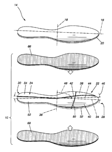
Referring to FIG. 1, there is shown a weighted footwear insert 10 in
accordance with an
embodiment of the present invention. The weighted footwear insert 10 is
adapted for use
inside a conventional footwear such as the footwear 12 shown in phantom lines
in FIG.
2. Typically, the weighted footwear insert 10 is designed so as to be
positionable inside
the footwear 12 underneath the footwear insole 14.
A conventional footwear insole 14 is shown in greater details in Figure 1. The
conventional footwear insole 14 typically has an elongated configuration
defining an
insole longitudinal axis 16, a generally perpendicular insole transversal axis
18 and an
insole peripheral edge 20. The footwear is designed so as to be wearable by
the foot of
an intended user (not shown).
The weighted footwear insert 10 includes a weighted plate 22 defining a plate
first
surface 24, a plate second surface 26, a plate toe end 28, a plate heel end 30
and a
plate peripheral edge 32. The weighted plate 22 also defines a plate
longitudinal axis 34
and a generally perpendicular plate transversal axis 36.
The weighted plate 22 is configured and sized for insertion into the footwear
12 with the
plate longitudinal axis 34 extending in a direction generally parallel to the
insole
longitudinal axis 16 and the plate transversal axis 36 extending in a
direction generally
parallel to the insole transversal axis 18.
16
CA 02364079 2001-12-05
The weighted plate 22 defines a first pair of plate segments 38, 40. The plate
segments
38, 40 define a segment longitudinal fold line 42 therebetween for allowing
the plate
segments 38, 40 to fold relative to one another about said segment
longitudinal fold line
42.
The segment longitudinal fold line 42 defines a longitudinal fold line
orientation axis 44.
The longitudinal fold line orientation axis 44 defines a longitudinal fold
line to longitudinal
axis angle 46 between the longitudinal fold line orientation axis 44 and the
plate
longitudinal axis 34.
The longitudinal fold line orientation axis 44 also defines a longitudinal
fold line to
transversal axis angle 48 between the longitudinal fold line orientation axis
44 and the
plate transversal axis 36. The longitudinal fold line to longitudinal axis
angle 46 is smaller
in value than the longitudinal fold line to transversal axis angle 48 so that
the longitudinal
segment fold line 42 extends in a more longitudinal than transversal
direction.
Typically, the segment longitudinal fold line 42 extends in a parallel
relationship relative
to the plate longitudinal axis 34. In some situations, it may be desirable
that the
longitudinal segment fold line 42 extends at an angle relative to the plate
longitudinal
axis 34.
In other situations such as exemplified by the embodiments shown in Figures 1,
5a, 6
and 7 at least one of the longitudinal fold lines 42 will have a somewhat
curved general
configuration. In such instances, the segment longitudinal fold line
orientation axis 44 is
defined as an axis splicing through the segment longitudinal fold line 42 and
averaging
the general direction of the segment longitudinal fold line 42. In the example
shown in
Figure 1, the segment longitudinal fold line orientation axis 44 is both
curved and at an
angle relative to the plate longitudinal axis 34.
The weighted plate 22 also includes a generally transversely extending
transversal
bending means for allowing said weighted plate 22 to bend so as to conform to
longitudinal variations in the contour of the sole of the foot of the intended
user.
Preferably, the transversal bending means includes a segment transversal fold
line 50
extending between the first pair of plate segments 38, 40 and a second pair of
plate
17
CA 02364079 2001-12-05
segments 52, 54. Typically, the first and second pair of plate segments 38, 40
and 52,
54 have their respective plate segments separated by the segment longitudinal
fold line
42. Preferably, the segment longitudinal fold line 42 extends across the
weighted plate
22 from the plate toe end 30 to the plate heel end 28.
In one of the preferred embodiments illustrated in FIG. 1 the weighted
footwear insert 10
defines a main segment longitudinal fold line 42 and a pair of auxiliary fold
lines 42'. The
main segment longitudinal fold line 42 extends substantially longitudinally
across the
weighted plate 22 and is substantially centrally positioned relative to the
plate peripheral
edges 32. The auxiliary longitudinal fold lines 42' are positioned on each
side of the main
longitudinal fold line 42 and follow directions so as to be in a generally
central position
between the main longitudinal fold line 42 and an adjacent plate peripheral
edge 32.
As illustrated in FIG. 2a, the weighted footwear insert 10 preferably defines
a plurality of
segment transversal fold lines 50 that extend across the weighted plate 22. It
should be
understood that although FIG. 5a illustrates a weighted footwear insert having
21
segment transversal fold lines 50, the number of segment transversal fold
lines 50 could
vary without departing from the scope of the present invention.
Also, although the transversal fold lines 50 illustrated in FIG. 5a are shown
having a
generally rectilinear configuration it should be understood that the segment
transversal
fold lines 50 could have a curved, sine waved, parabolic, hyperbolic or
otherwise shaped
configurations without departing from the scope of the present invention.
Typically, the transversal and longitudinal fold lines 42, 50 are shaped and
positioned so
as to optimize the movements of the weighted footwear insert 10 taking into
consideration the various joints of the human foot. The shape and position of
both the
longitudinal and transversal fold lines 42, 50 are optimized so as to take
into
consideration the various joints of the foot and the various possible
movements of the
foot including torsion as hereinabove mentioned.
18
CA 02364079 2001-12-05
For example, FIG. 6 illustrates another embodiment of the invention wherein
the
weighted footwear insert 10 defines a main segment longitudinal fold line 42
and a set of
auxiliary longitudinal fold lines 42'. The main segment longitudinal fold line
42 extends
substantially longitudinally across the weighted plate 22 and is substantially
centrally
positioned relative to the plate peripheral edges 32.
The auxiliary longitudinal fold line 42' are positioned on each side of the
main
longitudinal fold line 42 between the main longitudinal fold line 42 and
adjacent plate
peripheral edges 22. The auxiliary fold lines 42' extend from the plate toe
end 30 to a
position intermediate to the plate toe and heel ends 30, 28. The weighted
footwear insert
10 shown in Figure 6 also includes a plurality of segment transversal fold
lines 50 and a
generally U-shaped fold line 56 positioned generally adjacent to the plate
heel end 28.
FIG. 7 illustrates yet another example of a preferred embodiment of the
invention. The
weighted footwear insert 10 further includes a plate aperture 58 extending
through the
plate 22 adjacent to a ball-of-the-foot section 60. The plate aperture 58 is
filled with a
generally resilient material such as thin block or strip 62 of suitable
polymeric or
elastomeric resin. It should be understood that the configuration, size and
position of the
plate aperture 58 and associate block or strip 62 could vary without departing
from the
scope of the present invention.
The block or strip 62 not only provides a section having relatively resilient
characteristics, it also provides a section of lesser density thus allowing to
shift the
center of mass of the weighted plate 22 towards the plate heel end 28. This
shift in the
centre of mass could also be obtained by other means such as providing plates
of
various densities or configuration. Regardless of the method use, the
longitudinal or
transversal shift in the centre of mass relative to the centre of mass that
would be
obtained trough the use of a uniform plate allows for the targeting of
predetermined and
specific muscle groups during training.
19
CA 02364079 2001-12-05
In another embodiment of the invention (not illustrated), the longitudinal and
transversal
fold lines 42, 50 are configured and positioned so as to be substantially in
register with
the various joints of the human foot. In order to precisely take into account
the anatomic
and ergonomic inter-individual variations, the configuration and shape of the
longitudinal
S and transversal fold lines 42, 50 could be adjusted according to
measurements taken on
the intended user and the insert 10 could be customized according to a
manufacturing
method hereinafter disclosed.
As shown more specifically in FIG. 4b, in one embodiment of the invention, the
plate
segments are disposed relative to each other so as to define a segment spacing
64
therebetween. The weighted footwear insert 10 further includes a flexible
coupling
means attached to adjacent plate segment for flexibly coupling adjacent plate
segments
together so as to allow bending there between about the coupling means.
In a preferred embodiment of the invention, the flexible coupling means
include a first
flexible membrane 66 fixed to the plate first surface 24 on adjacent plate
segments. The
first flexible membrane extends across the segment spacings 64. Preferably,
the first
flexible membrane 66 is adhesively secured to the plate first surface using a
suitable
adhesive material.
Preferably, the flexible coupling means also includes a second flexible
membrane 68
fixed to the plate second surface 26 on adjacent plate segments. The second
flexible
membrane extends across the segment spacing 64 and is preferably adhesively
secured
to the plate second surface 26 using a suitable adhesive material.
Alternatively, as illustrated in FIG. 4c, the coupling means include a
flexible web 70 of
material extending integrally between adjacent plate segments. Although the
flexible
web 70 is shown extending from a position adjacent to the second plate surface
26 it
should be understood that the flexible web 70 could extend at other locations
between
adjacent plate segments.
CA 02364079 2001-12-05
Optionally, the coupling means allows bending of the plate segments only
within a
predetermined limited bending range or offers predetermined resilient
resistance to the
bending. For example, the coupling means could selectively limit the bending
range or
increase the bending resistance in the area adjacent the heel end 28 so as to
target the
muscles linked to that area. The limiting of the bending range and/or increase
in bending
resistance could be accomplish through different shapes of web 70, localized
variations
in the physical characteristics of the flexible membranes 66, 68, filling of
some or all of
the spacings 64 with suitable material or any other suitable means.
Optionally, the plate segments are made of materials having different
densities.
Optionally, the plate segments have different cross-sectional configurations
or different
thickness. For example, the various plate segments could be individually
shaped so that
assembled together they form an elevated arch support.
Typically, the plate segments are adapted to move independently one from the
other.
Furthermore, since a plurality of plate segments is preferably used, the
pressure exerted
by the foot of the intended user is directly transmitted to the shoe structure
with reduced
undue redistribution or attenuation.
Typically, although by no means exclusively, the thickness of the weighted
plate 22 has
a value substantially in the range between 35 and 85 thousands of an inch.
Also,
preferably, the weighted plate 22 is made out of steel, magnetic, or other
suitable
material. Also preferably, the flexible membranes 66, 68 are made out of nylon
or out of
a suitable polymeric or elastomeric resin.
The present invention also relates to a method of forming a weighted footwear
insert.
The method includes the steps of first cutting a blank having substantially
the planform
of an insole out of a relatively thin piece of generally dense material. Once
the blank is
formed, the second step involves forming at least one generally longitudinally
oriented
longitudinal fold line 42 and a set of generally transversally oriented
transversal fold lines
50 in the blank.
21
CA 02364079 2001-12-05
Various methods could be used for forming both the blanks and the longitudinal
and
transversal fold lines 42, 50. For example, a conventional punch and dye
method could
be used especially in situations wherein the embodiment including a flexible
web 70
between adjacent plate segments is preferred. Alternatively, sources of
localized energy
such as a laser or a high-pressure water cutter could be used.
When a source of localized energy is used as a cutting means the pattern of
the cutting
head is preferably optimized. As illustrated in FIG. 5b the fold lines are
preferably initially
cut so that a corner section 72 of each plate segment remains attached to an
adjacent
plate segment. This allows the plate to remain substantially integral for
handling and
further processing such as mounting of the optional flexible membranes 66, 68
shown in
FIG.1. The corner sections 72 linking adjacent plate segments at corner
sections thereof
are eventually severed either during manufacture or use. They are configured
and size
so as to minimize the risks of chaffing.
Optionally, the method of forming the weighted footwear insert 10 further
includes the
step of initially determining an optimized blank configuration and fold line
pattern for the
foot of the intended user, taking into consideration the physiological
characteristics of the
foot prior to cutting the blank and the longitudinal and transversal fold
lines 42, 50
according to the optimized blank configuration and fold line pattern.
For example, the optimized blank configuration and fold line pattern can be
determined
using conventional foot sensors typically used for evaluating weight
distribution on the
sole of the foot of an intended user. Once the weight distribution is
established a suitable
algorithm preferably incorporated into a computer program can be run for
determining
the optimized blank pattern and positioning of the fold lines taking into
consideration
anatomical considerations such as the precise positioning of the foot joints.
22