Note: Descriptions are shown in the official language in which they were submitted.
CA 02364183 2001-11-29
NASAL VENTILATION INTERFACE
FIELD OF THE INVENTION
The present invention relates generally to nasal ventilation systems, and more
particularly, to a valued nasal ventilation interface for supporting
respiration.
BRIEF DESCRIPTION OF THE PRIOR ART
Nasal ventilators generally consist of tubes and other means for delivering
gases adapted
for use with the nasal or oral passage of a patient. Typically, a nasal
ventilation system
comprises a gas source and a mechanical ventilator such as a continuous
positive airway
pressure system (CPAP), bi-level positive airway pressure system (BIPAP), o,~
intermittent (non-continuous) positive pressure (IPPB). The gas is often room
air or
oxygen-enriched air, but can be a mixture of other gases.
The gas is transported by a thin flexible tube made of an inert material. The
tube
terminates in an opening which can be inserted into the patient's nostrils.
Typically, a
pair of smaller nasal insert tubes protrude from the tube or the tube splits
at a Y junction
into two smaller tubes, each smaller nasal insert tube carrying gas to one
nostril, thereby
increasing the fraction of inspired oxygen.
Conventional nasal tube systems do not provide a positive seal between the
nasal insert
tubes and the nostrils. Most nasal ventilation systems therefore include a
mask that fits
over the nose and is intended to provide a space of oxygen-enriched air for
inhalation into
CA 02364183 2001-11-29
2334-1-2
the lungs for respiration. Such systems frequently suffer from air leaking out
around the
mask, creating an inability to assure ventilation in many patients.
For example, conventional nasal ventilation systems use head gear and/or
straps to bind
the mask in place, but in order to minimize the leakage of the air the straps
must be
sufficiently tight. The mask, headgear, and/or straps thereby exert more than
a minor
pressure on the patient's face and/or head, resulting in such masks and
headgear tending
to be rather constraining and uncomfortable.
Additionally, most systems are usually very position dependent, whereby if the
mask is
moved slightly with respect to the facial contour or with respect to the nose,
air leakage
occurs. With such systems, the mask can become uncomfortable when not in
position,
thus requiring the patient to remain rather still in order to alleviate the
discomfort and to
maintain oxygen inspiration. As a result many patients lose interest in using
the nasal
mask.
Also, some ventilation systems have exhalation valves for the treatment of
breathing
problems. Various valve systems have been devised but they all function
similarly.
Typically, the exhalation valve is positioned at the ventilator or in the
tubing at least a
foot or more from the patient, and the air that is exhaled by the user is
trapped in this
"dead space" between the patient and the valve. Such ventilation systems with
exhale
valves are typically bulky and heavy. The patient thus has to have a tidal
volume (breath)
that is a little larger than otherwise needed to compensate for the deadspace.
This larger
tidal volume is noticeable by the patient and can be a nuisance while trying
to sleep
2
CA 02364183 2001-11-29
2334-1-2
soundly.
Related types of nasal tube systems include low flow oxygen systems which
merely
provide oxygen concentration. These systems typically provide nasal insert
tubes that are
loosely inserted into the nasal cavities without a mask. Such systems are low
pressure
systems for providing oxygen enrichment to the ambient air that the patient
breathes, are
not ventilators (do not provide positive pressure for forced
ventilation/breathing), and
could not function as ventilation systems because of the lack of a seal
between the
cannula interface and the patient, the smaller tubing size, and the low
pressure of the
system.
Additionally, there are no known portable, wearable devices that completely
filter out the
allergens that trigger allergic reactions in asthmatics and allergy sufferers.
There are only
aerosol treatments and other medications that treat the symptoms, that is, the
allergic
reactions themselves. Furthermore, when a patient presents to an emergency
room with
severe bronchial constriction in response to allergens, a bronchodilator is
typically
administered to dilate the tracheal airways and bronchioles so that gas
exchange is
maintained in the alveoli of the lungs. However, if bronchial dilation is
successful then
allergens are also allowed to be breathed deeper into the bronchioles.
Bronchiole
constriction is a bodily reaction to keep any further allergens from reaching
the smaller
airways. Forced dilation and deeper penetration of allergens often results in
an even more
violent reaction after the bronchodilator has lost some of its therapeutic
effect. This
worsened reaction sometimes becomes life-threatening and can cause death, in
particular,
to a patient with status asthmaticus.
3
CA 02364183 2001-11-29
2334-1-2
Furthermore, present cloth surgical masks typically worn by doctors, surgeons,
and other
medical personnel do not filter out many pathogens. Also, they are hot to the
wearer and
can obstruct the wearer's view, especially when looking down during a surgical
procedure. Dentists are concerned with spray and do not trust the presently
available
surgical masks.
Accordingly, what is needed but not found in the prior art is a nasal
interface apparatus
that can be used with a positive pressure ventilation system for supporting
respiration,
that directs substantially all the air delivered to the nasal interface into
the patient's lungs,
that is comfortable and unconstraining to the patient wearer.
SUMMARY OF THE INVENTION
Generally described, the present invention provides a nasal ventilation
interface
comprising a hollow body having at least one and preferably two nasal
apertures, at least
one and preferably two inhale apertures, at least one and preferably two
connectors each
capable of being removably attached to at least one of preferably two
interface tubes, and
at least one and preferably two nasal insert tubes each associated with one of
the nasal
apertures of the body and capable of being inserted into a nostril of a
patient. Each nasal
insert tube has an annular sleeve with a contact surface and a diameter that
is greater than
a diameter of the nasal insert tube so that each annular sleeve contact
surface is thereby
capable of forming a seal with the nostril. The nasal insert tube may be
detachably
coupled to the hollow body. There may also be provided a three-way junction
capable of
being removably connected to a feed tube.
4
CA 02364183 2005-06-23
2334-1-2
The hollow body may have at least one exhale aperture and at least one valve
assembly
associated with the exhale aperture that is capable of preventing air from
passing through
the exhale aperture upon the patient inhaling and allowing air to pass through
the exhale
aperture upon exhaling. The hollow body may also have at least one filter that
retains
heat and/or moisture from air passing therethrough upon inhalation and that
transfers the
heat and/or moisture to the exhalation air that subsequently passes
therethrough upon
exhalation.
In a first embodiment of the present invention, each valve assembly comprises
a valve
member pivotally attached to a first inner wall of the body and a second valve
member
pivotally attached to a second inner wall of the body opposite the first inner
wall. The
first and second valve members overlap and abut each other so that each valve
member
may pivot in response to the other valve pivoting. In a second embodiment of
the present
invention, each valve assembly comprises a one-way inhale valve membrane
arranged in
the body between the nasal aperture and the exhale aperture or disposed within
the inhale
aperture, and a one-way exhale valve membrane disposed within the exhale
aperture. In a
third embodiment of the present invention, the body is provided for use
without the gas
supply, mechanical ventilator, or tubing, valuing may or may not be provided,
and a filter
is provided for screening out dust, allergens, pollen, bacteria, viruses,
pathogens, and
other air-borne particle matter, so that the invention may be used as a
portable nasal
filtration device.
Accordingly, it is a preferred feature of the present invention to provide a
positive
pressure closed system providing for full ventilation of a patient with oxygen
enrichment
5
CA 02364183 2005-06-23
capabilities typically provided by low pressure oxygen concentrator and
cannula tubing
systems.
It is another preferred feature of the present invention to provide a nasal
ventilation interface
having improved patient comfort for use over extended periods.
It is a further preferred feature of the present invention to provide a nasal
ventilation interface
having increased gas delivery efficiency and with minimal or no leakage of gas
from the
nostrils.
It is still another preferred feature of the present invention to provide a
nasal ventilation
interface having automatic valuing for inhaling and exhaling.
It is yet another preferred feature of the present invention to provide a
nasal ventilation
interface with a valve assembly that decreases the amount of deadspace that is
rebreathed by
the patient.
It is yet a further preferred feature of the present invention to provide a
nasal ventilation
interface that filters the air that is inhaled andJor exhaled for heat,
moisture, allergens, pollen,
bacteria, viruses, pathogens, and other air-borne particle matter.
According to the present invention then, there is provided a nasal ventilation
interface,
comprising at least one hollow body having at least one nasal aperture defined
therein and at
least one inhale aperture defined therein; at least one nasal insert tube
associated with each
nasal aperture of said body and capable of being inserted into a nostril of a
patient, each nasal
insert tube having at least one annular sleeve with a contact surface formed
thereon and with
a diameter that is greater than a diameter of said nasal insert tube, each
annular sleeve contact
surface capable of forming a seal with the nostril of the patient; at least
one exhale aperture
defined in said body and at least one valve assembly associated with said
body, said at least
one valve assembly being capable of preventing air from passing through said
exhale aperture
upon the patient inhaling and allowing air to pass through said exhale
aperture upon exhaling;
at least one first valve member having a first end and having a second end
pivotally attached
6
CA 02364183 2005-06-23
to a first inner wall of said body between said nasal aperture and said exhale
aperture; and at
least one second valve member having a first end and having a second end
pivotally attached
to a second inner wall of said body opposite said first inner wall and between
said exhale
aperture and said inhale aperture, said first valve member second end and said
second valve
member second end capable of abutting each other.
According to another aspect of the present invention, there is also provided a
nasal ventilation
interface, comprising at least one hollow body having at least one nasal
aperture defined
therein and at least one inhale aperture defined therein; at least one nasal
insert tube associated
with each nasal aperture of said body and capable of being inserted into a
nostril of a patient,
each nasal insert tube having at least one annular sleeve with a contact
surface formed thereon
and with a diameter that is greater than a diameter of said nasal insert tube,
each annular sleeve
contact surface capable of forming a seal with the nostril of the patient; at
least one exhale
aperture defined in said body; and at least one valve assembly associated with
said body, said
at least one valve assembly including at least one one-way inhale valve
membrane arranged
in said body between said nasal aperture and said exhale aperture or disposed
within said
inhale aperture and at least one one-way exhale valve membrane disposed within
said exhale
aperture, said at least one one-way inhale valve membrane and said at least
one one-way
exhale valve membrane each has at least one perforation defined therein with
at least one
biased closure member associated therewith such that air may pass through said
perforation
in one direction only; whereby, said at least one valve assembly is capable of
preventing air
from passing through said exhale aperture upon the patient inhaling and
allowing air to pass
through said exhale aperture upon exhaling.
These and other features, and advantages of the present invention are
discussed or apparent
in the following detailed description of the invention, in conjunction with
the accompanying
drawings and the appended claims.
BRIEF DESCRIPTION OF THE DRAWINGS
The various features and advantages of the invention will be apparent from the
attached
6a
CA 02364183 2001-11-29
2334-1-2
drawings, in which like reference characters designate the same or similar
parts
throughout the figures, and in which:
Fig. 1 is a side elevation view of a first preferred embodiment of the present
invention in
use by a patient;
Fig. 2 is a plan view of the embodiment of Fig. 1;
Fig. 3 is a side elevation view of the hollow body of the embodiment of Fig.
1;
Fig. 4 is a top plan view of Fig. 3.;
Fig. 5 is a side elevation view of the nasal insert tube of the embodiment of
Fig: 1;
Fig. 6 is a front elevation view of the nasal insert tube of the embodiment of
Fig. 1;
Fig. 7 is a side elevation view of the embodiment of Fig. 1;
Fig. 8 is a side elevation view of the first valve member of the embodiment of
Fig. 1 in a
first position;
Fig. 9 is a side elevation view of an alternative first valve member of the
embodiment of
Fig. 1;
Fig. 10 is a side elevation view of the first valve member of the embodiment
of Fig. 1 in a
second position;
Fig. 11 is a side elevation view of the first valve member of the embodiment
of Fig. 1
with a filter;
CA 02364183 2001-11-29
2334-1-2
Fig. 12 is a side elevation view of the first valve member of the embodiment
of Fig. 1
with a filter;
Fig. 13 is a side elevation view of a second embodiment of the present
invention during
the inspiratory cycle;
Fig. 14 is a side elevation view of the second embodiment of Fig. 13 during
the
expiratory cycle;
Fig. 15 is a side elevation view of a third embodiment of the present
invention;
Fig. 16 is a side elevation view of a first alternative third embodiment of
the present
invention;
Fig. 17 is a side elevation view of a second alternative third embodiment of
the present
invention during the inspiratory cycle; and
Fig. 18 is a side elevation view of the second alternative third embodiment of
Fig. 17
during the expiratory cycle.
DETAILED DESCRIPTION OF THE PREFERRED EMBODIMENTS
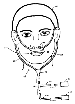
Referring now to Fig. 1, there is illustrated a first embodiment 10 of the
present nasal
interface invention as typically worn by a patient 12. The interface 10 may be
connected
by feed tubing 14 and a feed valve 16 to a mechanical ventilator 18 and a gas
supply 20.
The feed tubing 14 may be a thin flexible tube made of an inert material such
as
polyurethane, silicone, or another material known in the art. It will be noted
that all
a
CA 02364183 2001-11-29
2334-1-2
components of the interface 10 may be made of medical grade biocompatible
materials.
The mechanical ventilator 18 forces a gas such as air through the tubing 14.
The
mechanical ventilator 18 may be provided by a continuous positive airway
pressure
(CPAP) machine for constant air pressure delivered through the interface 10 to
the patient
12. Alternatively, the mechanical ventilator 18 may be provided by a bilateral
positive
airway pressure (BIPAP) machine for intermittent air pressure delivered
through the
interface 10 to the patient 12, whereby the pressure is lower during exhale
than during
inhale to facilitate breathing by the patient 12. Other mechanical ventilators
known by
those skilled in the art may be suitable, such as IPPB mechanical ventilators.
A power
source and controls (not shown) are provided for operating the mechanical
ventilator 18.
The gas supply 20 may be a tank of oxygen or another gas as may be appropriate
in a
given situation. The oxygen may be mixed with air to form oxygen-enriched air,
with the
oxygen concentration controlled by the valve 16. It will be understood that
other gases or
mists can be provided as may be desired in a given application.
Referring now to Figs. 1 and 2, there may be provided two lengths of interface
tube 22
each having a first end 24 and a second end 26, a three-way tubing junction 28
with two
connectors 30 each capable of being removably attached to one of the first
ends 24 of the
tube 22, and a hollow body 32 with two tubing connectors 34 each capable of
being
removably attached to one of the second ends of the tube 22. The three-way
tubing
junction 28 may be provided by a "Y" junction, a "T" junction, or another
junction as is
known in the art, with the connectors 30 of a type known in the art for
connecting tubing.
9
CA 02364183 2001-11-29
2334-1-2
The tube 22 may be a thin flexible tube made of an inert material such as
polyurethane,
silicone, or another material known in the art. The tubes 22 may be of a
smaller size than
tube 14 where two tubes 22 carry the same volume of gas as the one tube 14.
The feed
tube 22 size is selected to provide a sufficient air volume flow therethrough
for full
S ventilation of the patient 12. For example, the size of the feed tube 22 may
be selected to
accommodate about 120 liters per minute of air therethrough. On the other
hand, typical
low pressure oxygen cannula tubing is sized to accommodate about 5 liters per
minute.
Refernng now to Figs. 3 and 4, the hollow body 32 has at least one and
preferably two
nasal apertures 36 defined therein, at least one and preferably two inhale
apertures 38
defined therein, at least one and preferably two connectors 40 associated with
each inhale
aperture 38 and capable of being removably attached to said second ends of
said interface
tubing 22, and at least one exhale aperture 42 defined therein. The body 32
may be made
of a polycarbonate, plastic, polymer, metal, ceramic, composite, or other
material known
in the art. The body 32 may have a generally cylindrical, rectangular, or
other regular or
irregular shape. The connectors 30 are of a type known in the art for
connecting tubing.
Referring now to Figs. 5 and 6, there is provided at least one and preferably
two nasal
insert tubes 44 each capable of being inserted into a nostril of the patient
12. Each nasal
insert tube 44 has at least one annular sleeve 46 with a surface 50 formed
thereon for
forming a gentle but firm seal with the inner wall of one of the patient's
nostrils. The
annular sleeves 46 may be made of a soft pliable material for patient comfort
such as a
silicone elastomer or another material known in the art for providing a
surface for
forming the gentle but firm seal between the sleeve 46 and the patient's skin.
The annular
io
CA 02364183 2001-11-29
2334-1-2
sleeves 46 preferably have a generally oval shape for conforming to the shape
of the
patient's nostrils to form the seal as described herein, however, other
regular or irregular
shapes may be provided.
In order to secure the interface 10 in place without the need for headgear
and/or straps, a
force is generated by the sleeves 46 on the inner walls of the each nostril.
This is
accomplished by providing each sleeve 46 with a diameter that is greater than
a diameter
of the corresponding nasal insert tube 44. The contact surface 50 thereby
provides a
surface area sufficient to spread the required securement force over
sufficiently large area
of the inner walls of the nostrils for improved patient comfort. Additionally,
the lobes of
most patient's nostrils are generally angled, and each annular sleeve 46 may
have an
angled end 48 conforming thereto for allowing the annular sleeves 46 to be
inserted into
the patient's nostrils no more than is necessary to form the seal.
Each nasal insert tube 44 may be detachably coupled to the hollow body 32 so
that the
interface may be reused by merely changing out the sleeves 44 for each new
use. This
may be beneficial in certain applications, for example, for hospital or other
uses. Where
the interface is provided with detachable nasal insert tubes 44, the body may
be provided
with at least one and preferably two hollow members 52 extending from the body
32 (see
Figs. 3 and 4), each hollow member capable of detachably receiving one of the
nasal
insert tubes 44. The hollow members 52 may have a shape that is frusto-conical
which
provides a smooth transition of airflow from the body 32 into the nasal insert
tubes 44.
Alternatively, the hollow members may have a cylindrical or other regular or
irregular
shape.
11
CA 02364183 2005-06-23
2334-1-2
Alternatively, the nasal insert tubes 44 may be integrally formed with the
body 32, an
arrangement which may be beneficial in home use of the interface 10 where only
one
patient uses the interface 10. For such applications, the nasal insert tubes
44 may extend
directly from the body 32 without the need for the hollow members 52.
Referring now to Figs. 7-10, there is provided at least one and preferably two
exhale
apertures 54 defined in the body 32 and at least one valve assembly 56
associated with
and preferably arranged within the body 32. The valve assembly 56 prevents
inhalation
air 57 from passing through the exhale aperture 54 when the patient inhales
and allows
exhale air 59 to pass through the exhale aperture 54 when the patient exhales.
One of the
exhale apertures 54 is arranged between one of the inhale apertures 38 and one
of the
nasal apertures 36, and one of the valve assemblies 56 is arranged between one
of the
inhale apertures 38 and one of the nasal apertures 36.
The valve assembly 56 may comprise a first valve member 58 having a first end
60 and
having a second end 62 pivotally attached to a first inner wall 64 of the body
32 between
the nasal aperture 36 and the exhale aperture 54. The valve assembly 56 may
further
comprise a second valve member 66 having a first end 68 and having a second
end 70
pivotally attached to a second inner wall 72 of the body 32 opposite the first
inner wall
64 and between the exhale aperture 54 and the inhale aperture 38. The first
valve member
second end 60 and the second valve member second end 68 are capable of
overlapping
and abutting each other so that the valve members 60 and 68 may pivot in
response to
each other thereby providing for controlling the airflow through the body 32
as described
herein.
12
CA 02364183 2001-11-29
2334-1-2
The first valve member 58 is made of a material providing for one-way fluid
flow
therethrough. As shown in Figs. 8 and 9, for example, the first valve member
may have at
least one perforation 74 defined therein with at least one biased closure
member 76
associated therewith such that the inhale air 57 may pass through the
perforation 74 in
one direction only. For example, there may be provided one biased closure
member 76
for each perforation 74 (see Fig. 8), two biased closure members 76 for each
perforation
74 (see Fig. 9), or other similar arrangements known in the art. Also, the
biased closure
member 76 may have a generally frusto-conical shape whereby air may pass
through the
perforation 74 from the larger conical end through the smaller conical end,
but not vice
versa. The first valve member 60 may be made of a plastic, polymer, metal,
composite, or
other material known in the art. The second valve member 66 is non-perforated
and may
be made of a solid plastic, polymer, metal, composite, or other material known
in the art.
Fig. 7 shows the second valve member 66 pivoted to a first position where the
second
valve member 66 substantially covers the exhale aperture 54 in response to a
force
thereon from the patient 12 inhaling air 57 through the inhale aperture 38. In
this first
position, the exhale aperture 54 is substantially covered by the second valve
member 66
. alone, by a combination of the second valve member 66 and the first valve
member 58, or
by a combination of the second valve member 66, the first valve member 58, and
a stop
that will be described hereinafter. The first valve member 58 pivots to a
first position in
response to the pivoting of the second valve member 66 as a result of the
second end 68
of the second valve member 60 contacting and forceably moving the second end
60 of the
first valve member 58. The first valve member 58 is thereby suitably
positioned to
13
CA 02364183 2001-11-29
2334-1-2
receive a force from the exhale air 59 as will described immediately
hereinafter.
Fig. 10 shows the first valve member 58 pivoted to a second position in
response to a
force thereon from the patient 12 exhaling air 59 through the nasal aperture
36. When the
first valve member 58 pivots to the second position, the first valve member
second end 60
contacts the second valve member second end 68 and forces the second valve
member 66
to a second position. In this second position, the exhale aperture 54 is not
covered so that
the exhale air 59 may pass through the exhale aperture 54.
In order to limit the range of pivotal motion of the valve members 58 and 66
and thereby
maintain their second ends 60 and 68 in abutting contact, there may be
provided at least
one and preferably two stops 74 and 76 arranged within the body 32. The first
stop 74
limits the pivoting motion of the first valve member 58 to the first position
and the
second stop 76 limits the pivoting motion of the second valve member 66 to the
second
position. The stops 74 and 76 may be provided by rods, bars, tabs, arms, or
the like
extending across or into the body 32.
Alternatively to or in combination with the stops 74 and 76, the range of
pivotal motion
of the valve members 58 and 66 may be accomplished by the second end 60 of the
first
valve member 58 having an angled portion and the second end 68 of the second
valve
member 66 having a yoke or the like defined thereon that receives the angled
second end
60 when the valve members 58 and 66 are pivoted to the first positions. In
another
alternative, the second end 68 of the second valve member 66 has an angled
portion and
the second end 60 of the first valve member 58 has a yoke or the like defined
thereon that
14
CA 02364183 2001-11-29
2334-1-2
receives the angled second end 66 when the valve members are pivoted to the
first
positions.
Referring now to Figs. 11-12, at least one and preferably two filters 78 may
be provided
within the body 32. The filters 78 retain heat and/or moisture from the exhale
air 57
S passing therethrough. When the patient then draws his or her inhale air 59,
heat and/or
moisture retained by the filters 78 is absorbed into the inhale air 59 thereby
providing for
increased comfort of the patient 12. The filters 78 may be provided by an air-
permeable
filter material such as a fabric, plastic, fiber, composite, or other material
known by those
skilled in the art. The filters 78 may be arranged within the body 32 between
the nasal
aperture 36 and the exhale aperture 54, outside the body 32 adjacent the
exhale aperture
54, or in another position as will be understood by those skilled in the art.
Referring now to Figs. 13-14, there is provided a second embodiment 100 of the
present
invention. Similar to the first embodiment 10 described hereinabove, the
second
embodiment 100 has a body 102 with at least one and preferably two inhale
apertures
104; at least one and alternatively two or more exhale apertures 106, at least
one and
preferably two nasal apertures 108, and at least one valve assembly 110. Each
valve
assembly 110 may comprise at least one and preferably two one-way inhale valve
membranes 112 and at least one and alternatively two one-way exhale valve
membranes
114. The inhale valve membranes 112 may be arranged in the body 102 between
one of
the nasal apertures 108 and one of the exhale apertures 106 or may be disposed
within the
inhale aperture 104. The exhale valve membranes 114 may be disposed within the
exhale
apertures 106. The one-way inhale and exhale membranes 112 and 114 may be
provided
CA 02364183 2001-11-29
2334-1-2
of a material similar to that of the first valve member 58 of the first
embodiment 10. The
valve assembly 110 thereby prevents inhalation air 116 from passing through
the exhale
aperture 106 when the patient inhales and allows exhale air 118 to pass
through the
exhale aperture 106 when the patient exhales.
In the use of the first and second embodiments 10 and 100 of the present
invention, the
body 32 is positioned under the nose of the patient 12 with the nasal insert
tubes 44
inserted into the patient's nostrils and with the sleeves 46 securing and
sealing the body
32 in place. The lengths of interface tubing 22 are positioned over the
patient's ears so
that the junction 28 is positioned under the patient's chin or behind the
patient's back. The
mechanical ventilator 18 is operated to supply air to the nasal interface 10
at a positive
pressure, thereby forcing air through the feed tubing 14, the interface tubing
22, the
interface 10, and into the patient's nostrils and respiratory system to fully
sustain the
patient's breathing.
When the patient 12 inhales and initiates the inspiratory cycle, he or she
typically
generates about a negative 1 to 2 centimeters or so of water pressure. A
demand valve
(not shown) of the ventilator 18 may be triggered by this negative pressure
thereby
starting a positive flow of air into the interface 10. The patient 12 is
thereby able to draw
inhalation air 57 through the first valve member 58 in its first position, but
not through
the exhale aperture 54 as it is then covered by the second valve member 66.
Upon the tidal inhalation airflow 57 volume being delivered through the hollow
body 32
and nasal insert tubes 44 and to the patient's lungs, the positive pressure of
the inspiratory
16
CA 02364183 2001-11-29
2334-1-2
cycle flow ends. The patient 12 then initiates the expiratory portion of the
inhale/exhale
cycle. There is not enough back pressure to create static pressure in the body
32, so when
the patient 12 begins to exhale air 59 the first valve member 58 is forceably
pivoted to its
second position, thereby forceably pivoting the second valve member 66 to its
second
position where exhale air 59 may flow through the exhale aperture 54. The
cycle may
then repeat itself.
Referring now to Figs. 15-18, there is provided a third embodiment 200 of the
present
invention. Similar to the first embodiment 10 described hereinabove, the third
embodiment 200 has a hollow body 202 with at least one inhale aperture 204, at
least one
exhale aperture 206, and at least one and preferably two nasal apertures 208,
and at least
one nasal insert tube 210 removably coupled to or integrally formed with the
body 202
and in fluid communication with each nasal aperture 208. At least one valve
assembly
212 may be disposed within the body 202 as may be desired in a given
application.
The insert tubes 210 have annular sleeves 214 similar to those of the first
embodiment 10
such that each annular sleeve 214 forms a seal with the inner wall of the
nostril and
additionally exerts a force thereon sufficient to support the weight of the
third
embodiment interface 200 in place during respiration. In this embodiment, the
body 200
is not connected to interface tubing, a mechanical ventilator, or a gas
supply, so the body
202 need not have tubing connectors. Instead, the interface 200 provided is a
small,
lightweight, plug that is held securely in place by the annular sleeves 214.
The combined
cross-sectional area of the nasal apertures 208 and the combined cross-
sectional area of
the exhale apertures 206 are each therefore sized to provide a larger cross-
sectional area
m
CA 02364183 2001-11-29
2334-1-2
than that of the nostrils so that the patient does not blow the interface 200
out of his or
her nose when exhaling.
In the third embodiment 200, there is provided at least one filter 216
disposed within the
body 202. The filter 216 may be made of a material capable of retaining dust,
allergens,
pollen, bacteria, pathogens, and other air-borne particle matter from air
passing
therethrough. The filters 216 may be provided by an air-permeable filter
material such as
a thin layer of a treated fabric, plastic, fiber, composite, or other
material. For example,
the filter 216 may be made of a commercially available material known to be
used at the
air outlet (where the feed tubing 14 is connected) of some mechanical
ventilators 18.
When the patient 12 inhales, the undesired airborne matter is screened out of
the air by
the filter 216 before entering the patient's nostrils thereby providing for
increased health
and comfort of the patient 12.
The filter or filters 216 may be arranged within the body 202 in various
arrangements
several of which will now be described. As shown in Fig. 15, the at least one
inhale
aperture 204 may be provided by two apertures, the at least one exhale
aperture 206 may
be provided by two apertures, and the valve assembly 212 may be similar to
that of the
first embodiment 10. In a first alternative third embodiment as shown in Fig.
16, the at
least one inhale aperture 204 may be provided by two apertures, the at least
one exhale
aperture 206 may be provided by a single aperture, the at least one filter 216
may be
provided by a filter 216 in fluid communication with each inhale aperture 204
(without a
filter at the exhale aperture 206), and the valve assembly 212 may be similar
to that of the
second embodiment 100. In a second alternative third embodiment as shown in
Figs. 17-
is
CA 02364183 2001-11-29
2334-1-2 -
18, the at least one inhale aperture 204 and the at least one exhale aperture
206 may be
provided by a plurality of apertures spaced across a surface 218 of the body
202, the at
least one filter 216 may be provided by one filter 216 in fluid communication
with the
inhale and exhale apertures 204 and 206 and extending across the surface 218,
and the
interface 200 may be provided without a valve assembly. The apertures 204 and
206 in
the surface 218 may be provided along the length of the body 202 and/or around
the
perimeter or circumference of the body 202.
In the use of the third embodiment interface 200, the body 202 is inserted
into the
patient's nostrils before going to sleep, during particularly high pollen
count days, if the
onset of an allergic reaction is suspected, or at other opportune times as
will be
understood by those skilled in the art. The interface 200 is portable and may
be carned in
a patient's pocket so as to be readily available for use as a preventive
method of avoiding
an asthmatic attack and/or allergic reaction. The patient 12 merely inhales
and exhales as
normal, with the interface 200 held securely in place by the annular sleeves
214 and the
filter 216 screening out from air the allergens, dust, pollen, and/or like
undesired airborne
particle matter. The interface 200 is easily removed from the nostrils by
pulling it out by
the body 202.
The interface 200 can be also be provided with a filter 216 that screens
pathogens,
bacteria, viruses, and other airborne particle material from air. In this
arrangement, the
interface 200 can be used by doctors, surgeons, nurses, and other attendant
medical
personnel in operating rooms, dentists offices, clinics, and the like to avoid
causing
infection and disease in the patient whom they are treating.
19
CA 02364183 2001-11-29
2334-1-2
Accordingly, there are a number of advantages provided by the present
invention. The
nasal interface 10 provides the advantage of a positive pressure closed system
providing
for full ventilation of the patient 12 with oxygen enrichment capabilities
typically
provided by low pressure oxygen concentrator and cannula tubing systems.
The nasal interface 10 having the nasal insert tube 44 with the annular sleeve
46 provides
the advantage of improved patient comfort for use over extended periods.
The nasal interface 10 having the nasal insert tube 44 with the annular sleeve
46 provides
the advantage of increased gas delivery efficiency and with minimal or no
leakage of gas
from the nostrils.
The nasal interface 10 having a valve assembly provides the advantage of
decreasing the
amount of deadspace that is rebreathed by the patient.
The nasal interface 10 having a filter provides the advantage of filtering the
air that is
inhaled and/or exhaled for heat, moisture, dust, allergens, pollen, bacteria,
viruses,
pathogens, and other air-borne particle matter, for use in conjunction with a
continuous
positive pressure ventilation system or the like or for use as a discrete
nasal filtration plug
without a forced air supply.
While the invention has been described in connection with certain preferred
embodiments, it is not intended to limit the scope of the invention to the
particular forms
set forth, but, on the contrary, it is intended to cover such alternatives,
modifications, and
equivalents as may be included within the true spirit and scope of the
invention as defined
CA 02364183 2001-11-29
2334-1-2
by the appended claims. The terms "a" and "an" as used in the specification
and claims
herein are intended to include singular and plural quantities. All patents,
applications and
publications referred to herein are hereby incorporated by reference in their
entirety.
21