Note: Descriptions are shown in the official language in which they were submitted.
CA 02364203 2005-O1-20
TITLE : MA NETIC DIFFERENTIAL DISPLACEMENT DEVICE WITH
Dr~TRrBLITrNG FORCES PENDULUM AI~R_a_Y
FIELD OF THE INVENTION
This invention relates to electromagnets, in particular electromagnets for
displacement in space of physical bodies.
BACKGROUND OF THE INVENTION
In watercrafts, a substantial amount of the energy required for forward
thrust (e.g. with rearwardly located blade impellers) thereof is wasted due to
drag-
induced frictional forces, and in particular from the underlying body of water
on the
watercraft hull. Alternate methods of imparting thrust to a watercraft in a
way that would
reduce drag, would be welcome.
Sailboats tend to be more efficient than powerboats, but they depend upon
the whims of the wind, so they cannot be relied upon to go from A to B in a
set time.
Hydrofoils or hovercrafts are also quite efficient, but are very noisy and
their distribution
has always remain quite limited because of their inherent technical
limitations.
Use of electro-magnets in transport has been demonstrated with so-called
"maglev" trains tested in Japan, where the trains levitate at a very low
altitude over the
rail again to reduce frictional forces. However, these magnetic levitation
trains remain
1
CA 02364203 2001-11-28
for the time being mainly experimental, due to several major as yet unsolved
technical
challenges.
A magnet is a body that attracts iron and certain other material, by virtue
of a surrounding field of force produced by the motion of its atomic electrons
and the
alignment of its atoms. An electromagnet, in turn, is a magnet (consisting
essentially of a
soft-iron core) wound with a current-carrying coil of insulated wire, the
current in which
produces the magnetization of the core. Accordingly, the electromagnet
generates an
electromagnetic field of force associated with an accelerating electric
charge, having both
electric and magnetic components and containing a definite amount of
electromagnetic
energy.
OBJECT OF THE INVENTION
The gist of the present invention is therefore to provide an electromagnetic
device for providing motion and/or thrust to a watercraft.
SUMMARY OF THE INVENTION
In accordance with the object of the invention, there is disclosed a device
for enabling magnetic repulsive sliding displacement of two same-mass mobile
blocks,
where one block moves farther away than the other block relative to an
intermediate point
of reference. The blocks are connected to an intermediate stationary frame.
Electrical
current is applied on electromagnets pivotally mounted on one block, so that
repulsive
magnetic forces be applied between the two blocks.
More particularly, the invention relates to a differential displacement
electromagnetic device for providing motion over water of a watercraft, said
electromagnetic device including: a) an elongated rigid rail member, to be
anchored into
the watercraft against the watercraft bilge, said rail member having one and
another
2
CA 02364203 2001-11-28
opposite end portion, and a stopper member anchored at an intermediate middle
section
thereof; b) a first module member, slidingly carned by said rail member at
said one end
portion thereof; c) a second module member, slidingly carned by said rail
member at said
another end portion thereof, said second module member being of same mass as
said first
S module member but having a pivot mount at a central portion thereof: each of
said first
and second module member being magnetized; d) a biasing member, biasing said
first
and second module member toward one another, said first and second module
member
abutting against said stopper member under bias of said biasing member when
said
electromagnetic device is at rest; e) a pair of elongated rigid arms. each
having an firmer
end, pivotally mounted to said second module member pivot mount, and an outer
end; f)
a pair of electromagnets, each of said electromagnets fixedly mounted to a
corresponding
one of said rigid arms outer end; and g) a power source, operatively connected
to said
first module member and second module member for generating an electromagnetic
field
of force about said magnets and said electromagnets; wherein upon energizing
said power
source, magnetic repulsive sliding displacement of both said first and second
module
member occurs against the bias of said biasing member wherein said second
module
member travels by a longer distance along said rail relative to said first
module member,
and wherein upon de-energizing said power source, said first and second module
member
move toward one another and said first module member strikes said stopper
member
before said second module member, so that motion of the watercraft over water
may
occur.
Preferably, each of said first and second module member further includes a
notch
facing said stopper member, said notch of complementary shape to a registering
portion
of said stopper member, both such notches being engaged by said stopper member
when
said electromagnetic device is at rest.
The invention also relates to a a powered watercraft comprising a hull
including a
bow section, a stern section opposite said bow section. and a bilge
intermediate said bow
section and said stern section, and a differential displacement
electromagnetic device for
3
CA 02364203 2001-11-28
providing motion over water of said watercraft, said electromagnetic device
including: a)
an elongated rigid rail member, anchored into the watercraft against the
watercraft bilge,
said rail member having one and another opposite end portion and a stopper
member at
an intermediate middle section thereof; b) a first module member, slidingly
carned by
said rail member at said one end portion thereof; c) a second module member,
slidingly
carried by said rail member at said another end portion thereof, said second
module
member being of same mass as said first module member but having a pivot mount
at a
central portion thereof; each of said first and second module member being
magnetized;
d) a biasing member, biasing said first and second module member toward one
another,
said first and second module member abutting against said stopper member under
bias of
said biasing member when said electromagnetic device is at rest; e) a pair of
elongated
rigid arms, each having an inner end, pivotally mounted to said second module
member
pivot mount, and an outer end; f) a pair of electromagnets, each of said
electromagnets
fixedly mounted to a corresponding one of said rigid arms outer end; and g) a
power
1 S source, operatively connected to said first module member and second
module member
for generating an electromagnetic field of force about said magnets and said
electromagnets; wherein upon energizing said power source, magnetic repulsive
sliding
displacement of both said first and second module member occurs, against the
bias of
said biasing member wherein said second module member travels by a longer
distance
along said rail relative to said first module member, and wherein upon release
of said
energizing of said power source, said first and second module member move
toward one
another and said first module member strikes said stopper member before said
second
module member, so that said watercraft is provided with motion over water.
A CPU may be added, being operatively connected to said power source and to
said first and second module member, wherein there are at least two laterally
spaced said
electromagnetic device, and wherein said motion over water of said watercraft
consists of
steerable forward bow section thrust.
4
CA 02364203 2001-11-28
BRIEF DESCRIPTION OF THE DRAWINGS
Figure 1 is a schematic top plan view of a watercraft, with the
electromagnetic device of the invention and associated power source fitted
against the
bilge thereof;
Figures 2, 3 and 4 are enlarged schematic top plan views of the
electromagnetic device of the present invention, sequentially suggesting how
the pair of
magnetized modules move away from one another against the bias of the biasing
springs
and under the bias of an electromagnetic field;
and
Figure 5 is a schematic view of one of these modules, showing the two
pivotal arms and end weights pivotally mounted to this module.
DETAILED DESCRIPTION OF THE PREFERRED
EMBODIMENT OF THE INVENTION
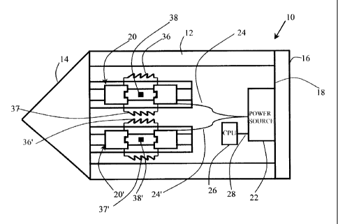
Figure 1 shows a watercraft 10 having a hull 12 including a tapered bow
section 14, a rounded stern section 16 opposite the bow section 14, and a
bilge 18
intermediate the bow section 14 and the stern section. A pair of differential
displacement
electromagnetic devices 20, 20', are spacedly mounted to the watercraft bilge
18, inside
the watercraft 10. A power source 22 - such as an electric generator or a
battery - is also
anchored to the watercraft bilge 18, and is connected to the electromagnetic
devices 20,
20', by electric lines 24, 24'. A central processing unit or CPU 26, is
operatively
connected by electric line 28 to power source 22 and to electromagnetic
devices 20, 20',
by lines 24, 24', respectively.
As illustrated in figure 2 of the drawings, each electromagnetic device 20
consists of an elongated rigid rail member 29 anchored to the watercraft bilge
18 in fore
and aft extending fashion. A pair of modular blocks 30. 32, are slidably
carried by rail 29
for coaxial sliding motion thereof along rail 29. Blocks 30, 32, each includes
an integral
magnet embedded therein. Blocks 30, 32, each has the same mass than the other.
S
CA 02364203 2001-11-28
A stopper member or post 38 is anchored to an intermediate section of
each rail 29, at the middle point between the two opposite ends of the rail
29. A pair of
tension coil springs 36, 37, interconnect the movable blocks 30 and 32, and
constitute a
biasing member biasing these blocks 30, 32 toward one another and against the
central
post 38. Preferably, each slidable block 30, 32, includes a notch 30a, 32a,
for
complementary engagement around a registering half section of post 38 when
blocks 30,
32 abut against one another under the bias of their tension springs 36, 37.
Post 38 may be
square in cross section, as illustrated, or circular in cross section, or
other suitable forms.
At rest or equilibrium, i.e. when no magnetic field is applied, the two
movable modules 30, 32, abut against one another around the central post 38,
over their
common elongated rail 29, as illustrated in figure 2. Under the impulse of the
electromagnetic field, modular blocks 30, 32, move repulsively away from one
another,
against the bias of their tension springs 36, 37. Without the differential
displacement
system 20 of the present invention, these same-mass blocks 30, 32, would move
away
from one another by the same relative distance. However, with the present
differential
displacement system, one block 30 moves farther away than the other block 32
(figure 3).
Figure 5 shows the slidable module block 30. Block 30 includes a main
body 40 having a pivot mount 42 at a centre portion thereof. Two elongated
rigid arms
44, 46, are pivotally mounted at their inner ends to the same pivot mount 42.
To the
outer end of each rigid arm 44, 46, is fixedly secured an electromagnet 48,
50.
Figure 3 suggested that, under an applied electromagnetic field, when the
differential displacement system is applied onto the movable blocks 30, 32,
the pairs of
pivotal magnets 48, 50, travel divergingly away from their stationary pivotal
mount 42 on
the given movable block 30, so that block 30 travels over rail 29 by a
distance greater
than the other movable block 32. Consequently, the resultant vector of
displacement of
the second movable block 30 - which is coaxially of but in the opposite
direction of
6
CA 02364203 2001-11-28
displacement from the first movable block 32 - produces a greater speed, which
means a
greater displacement relative to the first block, as clearly shown in figure
3.
Figure 4 shows the moment when the electromagnetic field is de-
energized, which enable both tension springs 36, 37, to pull back both modular
blocks 30,
32, toward one another against the centre post 38. As both modules 30, 32, are
moving at
the same speed, the module 32 which is closer to the centre post 38 will
strike on post 38
before block 30, and thus module 32 gives an impulsion to the rail 29 before
module 30
reaches the centre post 38.
According to one embodiment of the present differential displacement
device, the differential displacement observed between the two modules 30 and
32, was
for example of the order of between 30 % and 40 % in travel speed .
The present differential displacement device can be applied to a machine
or a vehicle, but preferably a watercraft 10, that uses a differential
acceleration of two
modules of same mass, in view of obtaining a net external force in a closed
loop system.
Within a watercraft 10, the present electromagnetic device 20, when
anchored to the watercraft bilge 18, does generate motion of watercraft 10
over water.
When two or more such electromagnetic devices are mounted into the watercraft,
steerable forward thrust of the watercraft 10 can be obtained, without any
need for a
watercraft rudder or impeller externally engaging directly with the body of
water
supporting the watercraft. Such forward thrust of the watercraft 10 is enabled
by the
electromagnetic devices 20, and steerable forward thrust thereof is controlled
by
coordination of the travel of oscillating modular members 30, 32 via the CPU
26.
In a motor vehicle (not shown) for use on a road, the present differential
displacement device could be use to dampen the centrifugal forces applied to
the motor
vehicle when the motor vehicle engages with speed into curbs. This
differential
7
CA 02364203 2001-11-28
acceleration is borne by a pair of electromagnets pivotally mounted to one of
the movable
modules for acceleration in a direction arcuately transverse to that of the
displacement of
the movable modules, so that one module moves faster than the other for a same
force
applied to both modules and even though both modules have the same mass.