Note: Descriptions are shown in the official language in which they were submitted.
CA 02364488 2001-08-31
WO 00/53392 PCT/NLOO/00138
Thermoplastic tube.
The invention relates to the production of tube from
thermoplastic material, in particular from polyolefin plastic
material, such as polyethylene. The invention also relates to
the production of plastic tube in which the thermoplastic
material is biaxially oriented, which process is known as the
biaxial stretching process. The invention also relates to
improvements to the process for the production of extruded tube
from thermoplastic material, which process may form part of the
production of biaxially oriented plastic tube. The invention
additionally relates to the production of an improved joint
between tubes made from biaxially oriented thermoplastic
material.
The present invention relates in particular to the
production of a tube from biaxially oriented thermoplastic
material with an integrally formed socket at an end, so that
tubes of this nature can be coupled to one another via socket
joints, in order in this way to form a pipe, for example for
transporting water, gas, etc.
WO 95/25626 has disclosed a method according to the
preamble of claim 1 for the production of biaxially oriented
plastic tube, also known as a stretched tube. In this method,
the stretched tube is of uniform cross tection, i.e. has a
uniform wall thickness and diameter, over its entire length, and
is also uniformly stretched in the axial and tangential
(circumferential) direction of the tube over its entire length.
A method for providing a tube which has been produced in this
way with a socket at one of its ends is known from WO 97/33739.
Another method for producing tube from biaxially
oriented plastics material is known from GB 1 589 052. This
method is based on a tube made from thermoplastic material which
has not been subjected to biaxial orientation, which tube has a
tube body with, at one end, an end part with a greater wall
thickness than the tube body. The tube is placed in a die and is
expanded by an internal pressure so that the plastics material
CA 02364488 2001-08-31
WO 00/53392 - 2 - PCT/NLOO/00138
of the tube is biaxially oriented. In the process, the end part
is deformed to form a socket.
WO 98/13190 has described yet another method for the
production of a tube with an integral socket from biaxially
oriented thermoplastic material.
Despite all the developments in the field of the
production of tubes from biaxially oriented thermoplastic
material, and in particular in the field of forming a socket on
a tube of this nature, load tests still show that the socket of
a tube of this nature forms the critical part of the tube. This
is because the tube has been found to rupture earlier at the
socket than in the tube body, and therefore the socket
constitutes an undesirable limitation on the mechanical strenght
of the tube.
The object of the present invention is to propose
measures which make it possible to produce a tube of the above
type with an integral socket at one or both ends. The invention
also provides measures for improving the spigot of the tube,
which is to be fitted into a socket.
For this purpose, the invention, according to a first
aspect, provides a method according to claim 1. When the method
according to the invention is carried out, an axial preform part
with a different wall thickness from the preceding part of the
preform is periodically formed in the section between the
extruder die and the tube speed-control means, in practice in
particular immediately downstream of the extruder die.
Surprisingly, in practice it has proven possible to
control the process of biaxial stretching of the preform
successfully despite the variation in the wall thickness of the
preform which is to be forced over the mandrel. In particular,
it has proven possible for a preform part with a greater wall
thickness to be forced over the mandrel without this having
undesirable effects on that part of the preform which has a
smaller wall thickness and is located between the said thick
preform part and the drawing device.
The method according to claim 1 enables a stretched tube
of biaxially oriented thermoplastic material to be produced in a
CA 02364488 2001-08-31
WO 00/53392 _ 3 _ PCT/NLOO/00138
continuous process with axial tube parts which have varying wall
thicknesses.
In practice, it has proven expedient for the maximum
wall thickness of the preform to be 5-15o greater than the
smallest wall thickness of the preform, as seen at a location
immediately downstream of the extruder die. It will be clear
that other values also lie within the scope of the invention.
Preferably, the transition from one wall thickness value
to another wall thickness value is gradual. This is of benefit
to the stability of the process.
In a preferred embodiment, the ratio between the
advancement speed of the preform, which is determined by the
tube speed-control means, on the one hand, and the output of the
extruder, on the other hand, is to be at a substantially
constant first value for a first period and to be at one or more
values which differ from the first value for a second period,
which is considerably shorter than the first period, which cycle
is repeated continuously.
In practice, this means, as seen at a point downstream
of the expansion mandrel - the stretched tube in each case has a
part of great axial length with a uniform first wall thickness
and associated diameter, which part is followed by a
considerably shorter axial part of the tube in which the wall
thickness differs from the said first wall thickness, in
particular is of one or more greater values, as seen in the
axial direction of the said shorter part. In particular, there
is provision for the wall thickness - as seen in the axial
direction - to vary between a plurality of values in the latter
axial part, so that annular areas which adjoin one another and
have different wall thicknesses can be distinguished in the
relevant part of the stretched tube.
The method according to the first aspect of the
invention can be implemented by periodically varying the output
of the extruder, in which case the advancement speed of the
preform which is determined by the tube speed-control means is
kept substantially constant. This does require an extruder which
can be adjusted within a suitable range in terms of its output.
CA 02364488 2001-08-31
WO 00/53392 _ 4 _ PCT/NLOO/00138
However, the method according to the first aspect of the
invention can also be implemented, as is preferred, by keeping
the output of the extruder substantially constant and
periodically varying the advancement speed of the preform which
is determined by the tube speed-control means.
In a preferred embodiment of the method according to the
first aspect of the invention, the stretched tube acquires
substantially the same axial stretching over its entire length.
To achieve this, in the method according to claim 3 it is in
some cases sufficient to keep the advancement speed of the
stretched tube downstream of the mandrel, which is determined by
the drawing device, constant, so that the ratio of the
advancement speed of the stretched tube downstream of the
mandrel, on the one hand, and of the preform upstream of the
mandrel, on the other hand, remains substantially constant.
In the method according to claim 4, the advancement
speed of the preform upstream of the mandrel, which is
determined by the tube speed-control means, varies, and for this
reason it is then necessary for the advancement speed of the
stretched tube downstream of the mandrel, which is determined by
the drawing device, to be varied periodically in such a manner
that the ratio of the advancement speed of the tube downstream
of the mandrel, on the one hand, and of the preform upstream of
the mandrel, on the other hand, is kept substantially constant.
In a variant of the method according to the first aspect
of the invention, there is provision for the tube parts with a
greater wall thickness not to have the same level of axial
stretching as an intervening tube part with a smaller wall
thickness, but rather to have a greater level of axial
stretching. For this purpose, in the period during which a part
of the preform with a greater wall thickness is being forced
over the mandrel, or during a section of this period, the ratio
of the advancement speed of the stretched tube which is
determined by the drawing device, on the one hand, and the
advancement speed of the preform which is determined by the tube
speed-control means, on the other hand, is greater than in the
period during which a part of the preform with a smaller wall
thickness is being forced over the mandrel, in such a manner
CA 02364488 2001-08-31
WO 00/53392 _ 5 _ PCT/NLOO/00138
that a tube part having the greater wall thickness acquires a
greater level of axial stretching than a tube part with a
smaller wall thickness.
To enable the method according to the first aspect of
the invention, and in particular according to the variant
described above, to be controlled successfully, it is desirable
for the tube to undergo its axial stretching in an accurately
defined section and, outside this section, for no further,
additional axial stretching to be generated in the tube. To
achieve this, an advantageous embodiment of the method according
to the first aspect of the invention provides for the stretched
tube downstream of the expansion part of the mandrel to be
cooled in such a manner that the cooled tube no longer undergoes
any axial stretching and the generation of the axial stretching
is concentrated in the section between the tube speed-control
means arranged in the vicinity of the extruder and the
downstream end of the mandrel. Preferably, the axial stretching
is realized between two tube speed-control means which are
arranged at a distance from one another and are both arranged
between the extruder and the mandrel.
It will be clear that at the moment at which a preform
part with a thickened wall arrives at the upstream end of the
mandrel, a possibly critical change occurs in the hitherto
stable condition of the method, in particular if the thickened
wall part of the preform projects inwards at that moment and
thus has a smaller diameter than the adjoining parts of the
preform. It would then be expected that the preform part with
the greater wall thickness would, as it were, jam on the
mandrel, while the thin and still hot part of the preform
located immediately downstream of this part would be
additionally stretched in the axial direction, possibly to an
unacceptable extent.
To solve this problem, in an embodiment of the method
according to the first aspect of the invention which is
advantageous in practice, the temperature of the preform is
controlled in such a manner that a preform part with a greater
wall thickness is on average at a higher temperature, measured
at a location immediately upstream of the mandrel, than a
CA 02364488 2001-08-31
WO 00/53392 _ 6 - PCT/NLOO/00138
preform part of a smaller wall thickness which adjoins this part
immediately downstream and is therefore already on the mandrel.
If it is assumed that the temperature conditioning
substantially consists in cooling the preform, although it is
also known from the prior art to supply (relatively small)
amounts of heat to the preform upstream of the mandrel, the
above-described temperature condition of the preform can in
practice be implemented by causing the cooling means, which form
part of the temperture-control means, to operate substantially
constantly. This can be explained in the following way. In the
section between the extruder die and the mandrel it is in fact
possible to distinguish between three partial sections. In the
first partial section which immediately adjoins the extruder
die, it is possible to produce a preform part with a thickened
wall by operating as described in claim 1. In the adjoining
partial section, the preform is subjected to the action of the
temperature-conditioning means, in particular to cooling, and in
the adjoining third partial section, there is in fact no
significant thermal energy supplied to or removed from the
preform.
In the method according to claim 3, a preform part with
a thickened wall which is formed in the first partial section
will move past the temperature-conditioning means in the second
section at the same speed as a preform part with a smaller wall
thickness. In relative terms, the thicker preform part will
therefore be cooled to a lesser extent and will therefore arrive
at the mandrel at a higher average temperature; in particular,
the temperature of the core of the said thickened preform part
will be higher. Due to the higher temperature, the modulus of
elasticity will be lower and the thickened preform part will
therefore be easier to deform, in relative terms, a fact which
in practice can sufficiently compensate for the wall thickening
to avoid the above critical situation.
In the method according to claim 4, the speed of the
preform is reduced while a preform part with a thickened wall is
being formed. In this case too, the said preform part will form
in the first partial section. Due to the reduction in speed,
that part of the preform which is situated in the second partial
CA 02364488 2001-08-31
WO 00/53392 _ 7 _ PCT/NLOO/00138
section during this period will be subjected to cooling for a
longer time than that part of the preform which has already
passed through the cooling and is in the third partial section.
When the preform part with a thickened wall is complete, the
speed of the preform is increased again and the preform part
with a thickened wall will pass through the cooling at the said
higher speed and will thus be cooled to a lesser extent. When
the thickened preform part then arrives at the mandrel, the said
part can be deformed easily, while the thin wall part of the
preform which is located immediately downstream thereof is in
fact relatively rigid. A combination of the two effects makes it
possible to carry out the process successfully in a controllable
manner.
It can be seen from the above that, on the basis of the
temperature of the preform - within a temperature range which is
suitable for obtaining biaxial orientation - and the resultant
modulus of elasticity of the plastics material of the preform,
it is possible to control the axial stretching of the preform.
By causing the preform to be at a higher temperature locally,
for example at a thicker part thereof as described above, than
other parts of the preform at the time of axial stretching, it
is possible to ensure that, given a constant axial stretching
force exerted on the preform, the hotter part undergoes greater
axial stretching than the cooler parts, even if this hotter part
has a greater wall thickness. In a practical embodiment, it is
possible for the thinner parts of the preform to be at a
temperature of approximately 90 C and for a hotter, optionally
thicker, part to be at a temperature in the vicinity of 120 C.
Surprisingly, it has proven possible to pass the tube
through an external calibration device after it has passed the
expansion mandrel. In this case, it can be observed that the
thickened tube part, on leaving the mandrel, projects outwards
with respect to the adjoining parts of the tube and is then
pressed inwards by the external calibration device.
The method according to the first aspect of the
invention can be carried out in a continuous process, and in
this way it is possible to produce a tube from biaxially
oriented thermoplastic material with a tube part with a
CA 02364488 2001-08-31
WO 00/53392 _ 8 PCT/NLOO/00138
thickened wall at (regular) axial intervals from one another. By
then sawing, cutting or suchlike through the tube at the
location of the thickened tube parts, it is possible to produce
tube sections with, at one or both ends, an end part with a
larger wall thickness than the tube body. Furthermore, the
invention provides for the said tube sections then to be
subjected to a socket-forming operation, in which case an
integral socket is formed from an end part with a thickened
wall. In a variant - if both end parts are of thicker design -
one end part is deformed into a socket and the other end part is
used as a spigot. If appropriate, the said spigot is also
deformed further, for example is provided with one or more
formations, in such a manner that a positively locking socket
joint can be obtained.
In a practical embodiment, the tube section has a tube
body of uniform cross section and wall thickness with, at one
end, an integral socket and, at the other end, a spigot with a
wall thickness which is 3-10o greater than the tube body.
Particularly in those embodiments in which the end part
with a thickened wall - prior to the formation of the socket -
has undergone axial stretching which is greater than or equal to
the tube body with a smaller wall thickness, the socket obtained
has proven to have considerably better properties and a greater
load-bearing capacity than the known sockets on such tubes.
Preferably, after the socket has been formed, the axial
stretching of the socket is greater than or equal to the axial
stretching of the tube body.
Further advantageous embodiments of the method according
to the first aspect of the invention are described in the claims
and the description.
A second aspect of the present invention relates to a
method for producing a tube from biaxially oriented
thermoplastic material, which tube has a tube body and, at one
or both ends thereof, an integrally formed socket, in which
method a prefabricated tube of biaxially oriented thermoplastic
material is subjected to a socket-forming operation.
The invention provides for the prefabricated tube to
have an end part with a greater wall thickness than the tube
CA 02364488 2001-08-31
WO 00/53392 - 9 PCT/NL00/00138
body, the axial stretching of the end part prior to the socket-
forming operation being equal to or preferably greater than the
axial stretching of the tube body. It will be clear that a tube
of this nature can be produced using the method according to the
first aspect of the invention.
The shape of the socket may be complicated, for example
with circumferential ribs of different diameters which, on the
inside of the tube, form circumferential areas of different
diameters. It is also possible for the wall thickness of the
socket, as seen in the longitudinal direction of the tube, to
vary and at suitable, e.g. heavily loaded, locations to be
thicker than at other locations.
In one possible embodiment, the end part of the
prefabricated tube - as seen from its end face - has a plurality
of annular areas which adjoin one another and have a wall
thickness which fluctuates from one annular area to the next
annular area, in which case in a plurality of annular areas the
wall thickness is greater than the wall thickness of the tube
body. The wall thickness of the end part may thus be of a
plurality of values which differ from the wall thickness of the
tube body, depending on the socket-forming operation which is
yet to be carried out and the requirements which are imposed on
the socket.
In a preferred embodiment, an annular area with a
greater wall thickness than the tube body is deformed, during
the socket-forming operation, into an outwardly bulging groove
wall which delimits an internal groove in the tube, which is
adapted to accommodate a sealing ring.
A third aspect of the invention relates to the
production of a tube from biaxially oriented thermoplastic
material as described in the preamble of claim 21. In this
method, at least part of the desired axial stretching of the
tube has already been brought about in the preform, before the
preform is moved over the expansion mandrel. Then, as it passes
over the mandrel, the desired stretching in the circumferential
direction is produced, as well as any remaining part of the
axial stretching.
CA 02364488 2001-08-31
WO 00/53392 - 10 - PCT/NLOO/00138
In a known method, for example as described in
WO 97/10096, two speed-control means, in the form of generally
known drawing devices, are arranged upstream of the mandrel, in
which case the speed-control means in the vicinity of the
mandrel imparts a higher advancement speed to the preform than
the other speed-control means. This leads to axial stretching of
the preform with reduction of the wall thickness of the preform.
In practice, however, this known method of axial stretching has
proven insufficiently controllable, with the result that
undesirable variations may arise in the preform. Variations of
this nature, for example in the cross-sectional shape of the
preform, constitute a drawback when the preform subsequently
passes over the mandrel.
The third aspect of the invention provides improved
control of the axial stretching described above.
According to the third aspect of the invention, in the
method according to the preamble of claim 21, the preform, in
the section between the speed-control means, in which the
preform is axially stretched, is moved through a calibration
opening of a calibration device, which calibration device
reduces the external diameter of the preform. As a result, the
preform acquires an accurately controllable external diameter
before the preform reaches the downstream speed-control means
and subsequently passes over the expansion mandrel. Furthermore,
a significant level of axial stretching can be produced in this
section combined with a high level of stability and
controllability of the process.
A fourth aspect of the invention relates to a method
according to the preamble of claim 22 for producing a biaxially
oriented tube from thermoplastic material.
In this known method, the passage of the preform over
the expansion part of the mandrel constitutes a problematical
part of the production of the tube. In particular, the preform
has exhibited undesirable deformations during this part of the
production process.
The fourth aspect of the invention seeks to promote the
stability of the preform as it passes over the mandrel.
CA 02364488 2001-08-31
WO 00/53392 - 11 _ PCT/NLOO/00138
The invention achieves this objective by providing a
method according to the preamble of claim 22, in which the outer
surface of the expansion part of the mandrel is provided, at a
plurality of locations around the circumference of the expansion
part, with elongate grooves and/or ribs which extend in the
axial direction, and a film of liquid preferably being formed
between the expansion part of the mandrel and the tube.
In an advantageous embodiment, the expansion part of the
mandrel is provided with axial grooves which are formed at
regular angular intervals, preferably of between 3 and 10 , in
the outer surface of the expansion part, and in which the
grooves are preferably at most 5 millimetres deep, particularly
preferably between 0.5 and 3 millimetres deep.
A fifth aspect of the invention relates to a method for
producing a biaxially oriented tube from thermoplastic material
as described in the preamble of claim 25. As is generally known,
to force the preform over the mandrel, a considerable tensile
force has to be exerted on the stretched tube downstream of the
mandrel. When this tensile force is being exerted, it is
fundamentally undesirable for the stretched tube to be damaged
or permanently deformed.
The fifth aspect of the invention provides for the
possibility of exerting a high tensile force by arranging a
plurality of drawing devices which drive the stretched tube at
the same speed one behind the other downstream of the mandrel.
Also, according to the fifth aspect of the invention,
the tube is internally supported at the location where a drawing
device, arranged downstream of the mandrel, acts, preferably
with the aid of mechanical support means which, at the location
where the drawing device acts, comprise one or more support
surfaces which move with the tube and bear against the inside of
the tube, which support means are preferably attached to the
inner core of the extruder.
Preferably, the support surfaces of the support means
are driven in the direction of advancement of the tube.
In a variant, it is permissible for the stretched tube
to be deformed by the drawing device, namely, in particular, if
that part of the tube on which the said device acts subsequently
CA 02364488 2001-08-31
WO 00/53392 - 12 - PCT/NLOO/00138
no longer forms part of the tube which is to be marketed. For
this purpose, therefore, it is possible for a drawing device to
comprise one or more tube-engagement members which can each be
moved to and fro over an axial distance, preferably
approximately the length of a tube which is to be marketed, and
act on part of the tube, so as to deform the tube, and grip the
tube securely at that location, each tube-engagement member
being assigned an axial displacement mechanism in order to
displace the said member and the tube which is secured therein
in the axial direction.
The abovementioned measures and other measures provided
according to the invention are described in the claims and in
the following description and will be explained below, in
particular with reference to the drawings. In the drawing:
Figs. la and lb diagrammatically depict a side view, partially
in cross section, of an exemplary embodiment of an installation
for producing biaxially oriented thermoplastic tubing,
Fig. 2a shows a longitudinal section through part of the preform
immediately after it has passed through the calibration device,
Fig. 2b shows the part from Fig. 2a after it has passed over the
expansion mandrel,
Fig. 2c shows the part from Fig. 2b after it has passed through
the calibration device downstream of the expansion mandrel,
Fig. 2d shows the part from Fig. 2c after it has been deformed
into a socket,
Fig. 3a shows an illustration corresponding to Fig. 2a of
another embodiment of the preform,
Fig. 3b shows an illustration corresponding to Fig. 2d of the
part from Fig. 3a which has been deformed into a socket, and
Fig. 4 shows a cross section through part of an extruder die
according to the invention,
Figs. 5a and 5b diagrammatically depict a side view, partially
in cross section, of an exemplary embodiment of an installation
for producing biaxially oriented thermoplastic tubing,
Fig. 6 shows the detail II in Fig. 5a on an enlarged scale,
Fig. 7 shows a part of the mandrel from Fig. 5b on an enlarged
scale,
Fig. 8 shows a perspective view of the mandrel from Fig. 3,
CA 02364488 2001-08-31
WO 00/53392 - 13 - PCT/NLOO/00138
Fig. 9 shows a longitudinal section through a joint between two
tubes made from biaxially oriented thermoplastic material
according to the invention, and
Fig. 10 shows a view corresponding to Figures 5a, 5b of a part
of a variant of an installation for producing biaxially oriented
thermoplastic tubing.
Figures la and lb show, in two partial drawings which
should adjoin one another, diagrammatic representations of the
most important elements of an installation for producing
biaxially oriented thermoplastic tubing in a continuous process.
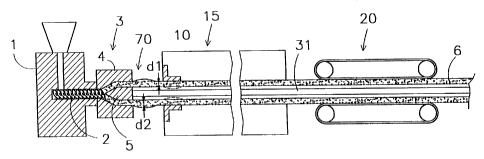
Fig. la shows an extruder 1 with one or more extruder
screws 2 and with an associated controllable drive, which
creates a flow of molten plastics material which is fed to an
extruder die 3 arranged on the extruder 1.
The extruder die 3 has an outer ring 4 and an inner core
5 which, together with the outer ring 4, delimits an annular
outlet opening, from which an extruded tubular preform 6 made
from thermoplastic material emerges in a substantially
horizontal direction. In this arrangement, the inner core 5
defines an axial space in the preform 6.
The extruder die 3 is provided with means for
controlling the wall thickness, which are not shown and can be
used to produce a uniform wall thickness (in the circumferential
direction) of the preform 6 coming out of the extruder die 3. An
internal cooling member may be attached to the inner core 3 for
internal cooling of the preform.
The preform 6 is externally calibrated with the aid of
external calibration sleeve 10.
Downstream of the calibration sleeve 10 there is a first
external cooling device 15, by means of which the preform 6 is
externally cooled. The external cooling device 15 comprises, for
example, a number of compartments which are located one behind
the other, through which cooling water flows and through which
the preform 6 moves, coming into direct contact with the cooling
water. If appropriate, the cooling water in each compartment is
at different temperatures, in order in this way to optimize the
cooling of the preform 6.
CA 02364488 2001-08-31
WO 00/53392 - 14 _ PCT/NLOO/00138
Downstream of the external cooling device 15 there is a
tube speed-control means 20 which acts on the cooled outer layer
of the preform 6. The tube speed-control means 20 may in this
case be designed as a drawing device which is known per se and
has a plurality of tracks acting on the preform, which type of
drawing device is customary for the extrusion of plastic tubes.
A heater device 25 is arranged downstream of the tube
speed-control means 20. This device 25 comprises a plurality of
heater units which are positioned around the path for the
preform 6, can be controlled separately and are each directed
towards a sector of the circumference of the preform 6. As a
result, a separately controllable amount of heat can be fed to
each sector of the preform 6, for example six circumferential
sectors each of 60 .
The installation furthermore comprises an expansion
mandrel 30, which in this case is non-deformable, also described
here by the term dimensionally stable. The mandrel 30 is in this
case made from metal. The mandrel 30 is held in a stationary
position with respect to the extruder 1 and is in this case
attached to the inner core 5 by means of a anchor member 31.
At its upstream end, the mandrel 30 has a run-on part
32, which in this case is of substantially cylindrical design.
The said run-on part 32 is adjoined by an expansion part 33, the
external surface of which substantially corresponds to the
surface of a truncated cone with a diameter which increases in
the downstream direction. The said expansion part 33 is adjoined
by a run-off part 34 of the mandrel 30, which part 34 is of
substantially constant diameter, if appropriate tapering
slightly in the downstream direction. As a result of being
forced over the mandrel 30, the preform 6 changes into a
stretched tube 6'.
At the location of the mandrel 30, in particular of the
run-off part 34, there is a second external cooling device 40,
by means of which the stretched tube 6' is externally cooled. As
is generally known for the production of biaxially oriented
plastic tube, the stretched tube is cooled after it has passed
the expansion part of the stretching mandrel, so that as a
CA 02364488 2001-08-31
WO 00/53392 - 15 - PCT/NL00/00138
result the changes which have been brought about in the plastics
material of the tube are frozen.
A second external calibration device 45 is arranged at a
distance downstream of the mandrel 30, which calibration device
45 reduces the external diameter of the tube 6'.
The installation also comprises a drawing device 50
which is arranged downstream of the mandrel 30 and of the
external calibration device 45. The drawing device 50 is
intended to exert a considerable tensile force on the stretched
tube 6'. Downstream of the drawing device 50 there is a cutting-
to-length device (not shown), for example a sawing, cutting or
milling device, in order to cut sections of the desired length
from the tube 6' which has been produced.
The preform 6 coming out of the extruder die 3 has a
relatively thick wall, in order thus to allow the biaxial
stretching to take place. After the preform 6 leaves the
extruder die 3, at a high temperature, the preform 6 is
cooled/locally reheated by means of the first external cooling
device 15 and by means of the heater device 25 in such a manner
that the plastics material is at an orientation temperature
which is suitable for biaxial orientation thereof before the
preform 6 is forced over the expansion part 33 of the mandrel
30.
The preform 6 is forced over the mandrel 30 under the
influence of the forces which are exerted on the preform 6 and
the tube 6' by means of the drawing device 50 in conjunction
with the tube speed-control means 20. By means of the drawing
device 50 and the tube speed-control means 20, it is possible to
accurately control the advancement speed both at a location
upstream of the mandrel 30 (at tube speed-control means 20) and
at a location downstream of the mandrel 30 (at drawing device
50).
As a result of passage over the mandrel 30, the
molecules of the plastics material are oriented, i.e. stretched,
both in the axial direction and in the circumferential
direction, which is of great benefit to the properties of the
tube 6'.
CA 02364488 2001-08-31
WO 00/53392 - 16 - PCT/NLOO/00138
A unit for measuring the wall thickness may be arranged
between the extruder 1 and the mandrel 30, by means of which
unit the thickness of the preform 6 and the shape of the cross
section of the preform 6 can be measured.
Downstream of the mandrel 30 there is a unit 60 for
measuring wall thickness. This wall-thickness measuring unit 60
may be connected to a control unit which, on the basis of the
measured cross section of the stretched tube 6', controls the
operation of the drawing device 50, the device 25, and, if
appropriate, the distance between the calibration device 45 and
the mandrel 30.
The mandrel 30 may be provided with one or more feed
ducts which open out in the outer surface of the mandrel 30 and,
through the anchor member 31 and the extruder die 3, are
connected to pump means (not shown) for supplying a liquid
between the mandrel 30 and the preform 6. It is thus possible to
form a film of liquid between the preform 6 and the mandrel 30,
in particular between the preform 6 and the expansion part 33 of
the mandrel 30. It is also possible to form a film of liquid
between the run-off part 34 and the tube 6', serving to reduce
the friction between the tube and the run-off part and, on the
other hand, possibly also as internal cooling for the stretched
tube.
In a variant, it is possible to introduce a gas, in
particular heated air, under pressure between the non-deformable
mandrel 30, in particular the expansion part thereof, and the
preform 6, in order, in this way, to obtain a film of gas.
It is generally known from the prior art for the
installation described above to be operated in such a manner
that the preform 6 upstream of the mandrel 30 has, as accurately
as possible, a uniform cross section, i.e. wall thickness and
diameter, and also has a suitable orientation temperature which
is as uniform as possible. Downstream of the mandrel 30, the
stretched tube 6' then has a greater diameter and a smaller wall
thickness.
In contrast to this known way of operating the
installation, according to one aspect of the invention, it is
possible, by periodically varying the ratio between the
CA 02364488 2001-08-31
WO 00/53392 - 17 - PCT/NLOO/00138
advancement speed of the preform 6, which is determined by the
tube speed-control means 20, on the one hand, and the output of
the extruder 1, on the other hand, between a first value and a
second value, which is lower than the first value, for the
extruded preform 6, in the section between the extruder 1 and
the tube speed-control means 20, to alternately acquire a first
wall thickness - if the said ratio is of the first value - and a
second wall thickness - if the said ratio is of the second
value - the second wall thickness being greater than the first
wall thickness.
In the example presented here, this is effected by
keeping the output of the extruder 1 substantially constant and
by periodially varying the advancement speed of the preform 6
which is determined by the tube speed-control means 20. In this
case, therefore, the ratio between the advancement speed of the
preform 6, which is determined by the tube speed-control means
20, on the one hand, and the output of the extruder 1, on the
other hand, is kept substantially constant at the first value
for a first period, so that a long piece of preform 6 with a
first wall thickness "dl" is produced. During a second period,
which is considerably shorter than the first period, the speed
of the tube speed-control means 20 is set to a lower value, with
the result that a preform part having the second, greater wall
thickness "d2" is then formed immediately downstream of the
extruder die 3, as indicated in Figure la by reference
numeral 70.
The method provides for continuous production in which a
thickened preform part 70 is preferably obtained at regular
intervals.
During the external calibration 10, the preform 6
acquires a uniform external diameter, so that the thickened
preform part 70 projects inwards in that area with respect to
the preform part having the first wall thickness, as indicated
by a dashed line.
The thickened preform part 70 then passes through the
external cooling device 15 and arrives at the mandrel 30, where
the thickened preform part 70 is made to bulge outwards by the
run-on part 32 of the mandrel (indicated by a dashed line).
CA 02364488 2001-08-31
WO 00/53392 - 18 - PCT/NL00/00138
When it passes over the mandrel 30, the preform 6, and
consequently also the thickened preform part 70, is stretched
axially and in the circumferential direction, as will be
described in more detail below.
When it passes through the external calibration device
45, the thickened part 70 is pressed inwards again (as indicated
by a dashed line), resulting in a stretched tube 6' having
thickened parts 70 at (regular) axial intervals and, between
these thickened parts, in each case a long part of smaller wall
thickness dl.
In one practical embodiment, the tube 6' is cut to
length downstream of the drawing device 50 at each thickened
part 70, and the distance between two thickened parts 70
corresponds to the desired length of the tube sections to be
produced by cutting the tube 6' to length. As a result, each
tube section then has a tube body and, at one end, a thickened
tube part with a greater wall thickness than the tube body.
Preferably, the thickened end part of the tube is then subjected
to a socket-forming operation, so that a high-quality integral
socket can be obtained.
In another variant, the tube 6' is cut to length in such
a way that there is a thickened end part at each end of a tube
section. It is then possible for one of the ends to be deformed
into a socket, while the other end, possibly without further
treatment, can be used as a thickened spigot.
In a preferred embodiment of the method according to the
first aspect of the invention, the biaxially stretched tube
undergoes substantially the same axial stretching over its
entire length. Since the advancement speed of the preform 6
upstream of the mandrel 30, which is determined by the tube
speed-control means 20, varies, it is therefore necessary for
the advancement speed of the tube 6' downstream of the mandrel
30 which is determined by the drawing device 50 to be varied
periodically, in such a manner that the ratio between the
advancement speed of the tube 6' downstream of the mandrel 30
and of the preform 6 upstream of the mandrel 30 is kept
substantially constant during the production of both a thickened
part and an unthickened part.
CA 02364488 2001-08-31
WO 00/53392 - 19 - PCT/NL00/00138
In a variant of the method according to the first aspect
of the invention, there is provision for a thickened part 70 not
to undergo the same axial stretching as the intervening parts of
the first wall thickness di, but rather for the thickened part
70 to undergo greater axial stretching. For this purpose, in the
period during which a thickened part 70 is being forced over the
mandrel 30 or during part of this period, the ratio between the
advancement speed downstream of the mandrel 30 which is
determined by the drawing device 50 and the advancement speed
upstream of the mandrel 30 which is determined by the tube
speed-control means 20 is greater than in the period during
which a part of the preform which has the first wall thickness
d1 is being forced over the mandrel 30.
To enable the process to be controlled successfully, it
is desirable for the axial stretching of the preform to take
place within an accurately defined subsection of the
installation. For this purpose, it is possible for the stretched
tube 6' to be cooled downstream of the expansion part 33 of the
mandrel 30, in such a manner that the cooled tube 6' does not
undergo any further axial stretching and the generation of the
axial stretching is concentrated in the section between tube
speed-control means 20 and the downstream end of the mandrel 30.
To control the process, it is furthermore advantageous
for the temperature of the preform 6, upstream of the mandrel
30, to be conditioned with the aid of the cooling device 15 and,
if appropriate, to a slight extent by the heater device 25 in
such a manner that a thickened preform part 70 is on average at
a higher temperature, measured at a location immediately
upstream of the mandrel 30, than an immediately adjoining
downstream preform part of the first wall thickness di which is
already on the mandrel 30.
As has already been described, the speed of the preform
6 is reduced while the preform part 70 with a thickened wall is
being formed. As a result of the reduction in speed, that part
of the preform which during this period is located in the
cooling device 15 will be subjected to the cooling action for a
longer time than that part of the preform which has already
passed through the cooling 15. When the preform part 70 with a
CA 02364488 2001-08-31
WO 00/53392 - 20 - PCT/NLOO/00138
thickened wall has been formed, the speed of the preform 6 is
increased again and the preform part 70 will pass through the
cooling 15 at this higher speed and thus, in relative terms,
will be cooled to a lesser extent than the immediately
downstream part of the preform 6. When the thickened part 70
then reaches the mandrel 30, the said part 70 is hot and easy to
deform, while that part of the preform which is located
immediately downstream thereof and has a thinner wall is in fact
relatively rigid. Through a combination of the two effects, it
is possible to successfully force the thickened part 70 onto and
over the mandrel 30 without the part downstream thereof being
stretched excessively in the axial direction.
Tests have demonstrated that, in the case of PVC, the
wall thickness of the said thickened preform parts may be 15%
greater than that of the intermediate parts without causing any
problems.
Preferably, the variation in the wall thickness of the
preform 6 is always gradual, so that there are no abrupt
transitions from one wall thickness to the other wall thickness.
Incidentally, it is conceivable for the thickened
preformed parts not to be produced specifically for the
subsequent formation of a socket, but rather, for example, to
enable a branch pipe to be connected to the stretched tube. The
thickened tube part could also be used as a point for a drawing
device arranged, for example, downstream of the expansion
mandrel to engage on the tube, so that a high tensile force can
be exerted on the tube in order to force the preform over the
expansion mandrel.
The shape of the thickened part 70 shown in Figures la
and lb is, of course, only shown by way of example. In fact, it
has proven possible for the wall thickness of the thickened part
70 to be controlled accurately and, in this way, for a specific
profile to be imparted accurately to the wall of the thickened
part 70 as seen in the longitudinal direction of the tube.
Figure 2a shows a longitudinal section through half of
the preform 6 at a location immediately after it has passed
through the calibration device 10, having a thickened tube part
CA 02364488 2001-08-31
WO 00/53392 - 21 - PCT/NLOO/00138
170 produced by varying the speed of tube speed-control means 20
with respect to the output of the extruder 1.
In Figure 2a, dl denotes the first wall thickness which
is used.for a long part of the preform 6. The line 171 is the
centre axis of the preform 6. The thickened part 170 has a
profile with a plurality of wall thickness values, described by
points A, B, C, D, E, F and G.
Figure 2b shows the same thickened part as in Figure 2,
but in this case after it has passed over the mandrel 30. This
can be seen clearly from the greater diameter and reduced wall
thickness of the now stretched tube 6'. It is clear that the
internal diameter of the tube 6' is now uniform and the wall
thickness profile can be seen on the outside. The points A-G
show that stretching has taken place in the axial direction and
in the circumferential direction of the thickened part 170 when
it passed over the mandrel 30.
Figure 2c shows the part of tube 6' after it has passed
through the calibration device 45, which device, incidentally,
is optional in the method according to the first aspect of the
invention. The external diameter is now uniform once again,
while the profile can be seen on the inside.
As described, there is provision for the tube 6' to be
cut to length at the thickened part 170, in this case at line
172. Then, the cut-to-length tube section is subjected to a
socket-forming operation, during which the thickened part 170 of
the said tube section is deformed to form a socket.
Figure 2d shows a possible embodiment of that end of a
tube section which is provided with a socket and has been
produced as described with reference to Figures 2a, 2b and, if
appropriate, 2c.
At one end, the prefabricated tube section with a
thickened tube part 170 has a greater wall thickness than the
tube body, and the axial stretching of the thickened end part
prior to the socket-forming operation is equal to or preferably
greater than the axial stretching of the tube body. It will be
clear from the preceding text how a tube section of this nature
can be produced.
CA 02364488 2001-08-31
WO 00/53392 - 22 - PCT/NLOO/00138
In particular, Figure 2c shows that the end part of the
prefabricated tube, as seen from its end face, has a plurality
of annular areas which adjoin one another and have a wall
thickness which fluctuates from one annular area to the next
annular area, the wall thickness, in the case of a plurality of
annular areas, being greater than the wall thickness of the tube
body.
Then, during the socket-forming operation, in this case
the annular area between points B and E is deformed into an
outwardly bulging groove wall 173 which delimits an internal
groove 174 of the tube, which is intended to accommodate a
sealing ring (not shown).
The groove wall 173 may advantageously have a greater
level of axial stretching than the tube body with wall thickness
el, in particular if the thickened tube part 170 is produced in
such a manner that it already exhibited a greater level of axial
stretching prior to the formation of the socket than the
adjoining tube body, more or less beyond point G. The additional
wall thickness of the annular area from which the groove wall
173 is formed makes it possible to ensure that, even as a result
of the increase in diameter of the said part during the
formation of the socket, the final wall thickness of that part
is no less than that of the tube body. In particular, this is
possible without the axial stretching of the said part of the
tube being reduced or even converted altogether into negative
stretching through compression of the said part, as is known
from the prior art.
It will be clear that the advantages discussed with
reference to the groove wall 173 also apply to the other areas
of the socket which are formed from the thickened tube part 170.
Ultimately, therefore, it is possible to produce a tube section
from biaxially oriented plastic material which has a tube body
and an integral socket, the axial stretching of the socket being
equal to or preferably greater than that of the tube body. In
this case, the wall thickness of the socket may also be equal to
or even greater than that of the tube body.
In an illustration corresponding to Figure 2a, Figure 3a
shows another embodiment of a thickened part 190 which has been
CA 02364488 2001-08-31
WO 00/53392 - 23 - PCT/NL00/00138
produced using the method according to the invention. This
thickened part 190 has a first zone, indicated by points A-G,
which virtually corresponds to the description given with
reference to Figure 2a. The line 191 is the centre axis. Further
away from the end of the tube section to be produced, shown by
line 192, the thickened part 190 has a second zone, between
points G and H, with a wall thickness dl corresponding to the
thickness of the preform outside the thickened part 190. This is
followed by a third zone, indicated by points H-K, with a
greater wall thickness.
It can be seen in Figure 3b that only the first zone of
the thickened part 190 has been deformed into a socket. This
first zone is deformed in the same way as that described with
reference to Figure 2d and has a groove wall 193. The third zone
forms an inwardly projecting rim 194. This rim 194 serves to
receive a support bush which is introduced into the first zone
when the socket is being formed, in order to provide internal
support for this zone during heating. When the socket is being
formed, this support bush is then pushed further into the tube
and then comes to bear against the rim 194. This prevents the
support from penetrating too far into the tube and also prevents
this support bush from locally overheating the tube.
During the formation of a socket at the end part of a
biaxially oriented tube, in particular at the thickened end part
as explained above, it is deemed advantageous if, during the
formation of the socket using a socket-forming mandrel, the said
end part does not undergo any compressive strain, i.e. axial
compression. This is because compressive strain leads to a
reduction in the axial stretching in the end part which is
deformed into a socket, and this may be disadvantageous. For
example, it can be seen in WO 97/33739 that, during the
formation of the socket, pressure is exerted on the end side of
the tube, so that the compressive strain is generated.
To control such compressive strain during formation of
the socket, so that the compressive strain can be kept at a low
level or even avoided altogether, it is possible for the tube to
be provided, in the vicinity of its end side, with a holding
zone which lies between the said end and that part of the tube
CA 02364488 2001-08-31
WO 00/53392 - 24 - PCT/NLOO/00138
which is to be deformed into a socket. Before the socket-forming
mandrel is introduced into the tube, the tube is then gripped
and held in the said holding zone, while the socket-forming
mandrel is pressed into the end part of the tube as far as into
that part which is to be deformed into a socket, which part lies
beyond the holding zone, as seen in the insertion direction of
the mandrel. As a result of the holding zone being held,
undesirable and uncontrollable compressive strain on the end
part of the pipe is avoided. If appropriate, lubrication may
also be provided between the mandrel and the end part of the
tube, in order to reduce the friction between them.
Preferably, after the socket has been formed, the
holding zone is removed from the tube, for example by means of a
cutting or sawing device. Since this holding zone is
subsequently removed, it is also permissible for this zone to be
damaged when it is gripped. By way of example, a socket-forming
installation provided with a socket-forming mandrel and with
actuable holding means is used for gripping and holding the
holding zone of the tube. By way of example, the holding means
comprise teeth which lodge fixedly in the plastic in this zone.
In an advantageous embodiment, the holding zone is
designed as a thickened annular area of the tube. If
appropriate, the holding means form a type of collar which
engages behind the said thickened annular area.
Figure 4 shows a cross section through part of extruder
die 200 which is suitable for use in the method described above
and is used to extrude a preform 201 from thermoplastic
material. Furthermore, the figure shows a section of an external
calibration device 202 arranged downstream of the extruder die
200.
The extruder die 200 comprises an outer ring 205 and an
inner core 206, which between them delimit an annular gap for
the plastics material which is supplied by an extruder (not
shown).
The calibration device 202 is positioned closely behind,
virtually against, the extruder die 200, in order to prevent the
preform 201 from being exposed to the outside air for an
CA 02364488 2001-08-31
WO 00/53392 - 25 - PCT/NL00/00138
undesirably long time, which is advantageous from both a
chemical and a thermal point of view.
The calibration device 202 has a sleeve 207 which
defines the external diameter of the preform 201. The
calibration device 202 cools the outside of the preform, and a
solidified skin forms on the outside of the preform 201.
Immediately downstream of the extruder die 200, the
preform 201 is also cooled internally by means of an internal
cooling member 208, only part of which is shown.
As described above, there is provision for the wall
thickness of the preform 201 to be changed periodically in
order, in this way, to obtain a preform part with a greater wall
thickness, as shown in Figure 4. To obtain a preform part with a
greater wall thickness than that defined by the gap between the
inner core 206 and the outer ring 205, flowable plastic material
has to be able to flow from the extruder die 200 to the thicker
preform part. For this reason, it is undesirable for a
solidified skin to form on the inside of the preform,
immediately downstream of the inner core. To counteract this
skin formation, an insulating member 210 which is attached to
the inner core 206 is provided.
The insulating member 210 has a conical outer surface
211 which adjoins the outer surface of the inner core 206 and
has an external diameter which decreases in the direction of
extrusion. During the formation of a thickened part in the
preform 201, the plastic material then bears against the said
insulating member 210 and the formation of a solid skin is
prevented at that location. Preferably, the outer surface 211 of
the insulating member 210 lies at least partially inside the
outer ring 205. As a result, the swelling of the preform 201 to
obtain a thickened part in the preform 201 can take place even
upstream of the external calibration device 202 arranged closely
behind the extruder die 200.
In two partial drawings which are to adjoin one another,
Figures 5a and 5b diagrammatically depict the most important
elements of an installation for producing biaxially oriented
thermoplastic tubing in a continuous process.
CA 02364488 2001-08-31
WO 00/53392 - 26 - PCT/NL00/00138
The wall thickness of the tube to be produced is
preferably such that the tube is dimensionally stable. In
particular, it is intended to produce tube which is suitable for
the assembly of pipework systems for transporting liquid or gas,
in particular for drinking water, sewage water, natural gas or
the like. Preferably, the tube is suitable for laying in the
ground.
Figure 5a shows an extruder 301 having one or more
extruder screws 302 with an associated controllable drive, by
means of which a flow of molten plastic material is provided,
which is fed to an extruder die 303 arranged on the extruder
301.
The extruder die 303 has an outer ring 304 and an inner
core 305 which, together with the outer ring 304, delimits an
annular outlet from which an extruded preform 306 of
thermoplastic material emerges in a substantially horizontal
direction. In this arrangement, the inner core 305 defines an
axial space in the preform 306.
The extruder die 303 is provided with means for
controlling the wall thickness (not shown) by means of which a
uniform wall thickness (in the circumferential direction) of the
preform 306 coming out of the extruder die 303 can be produced.
An internal cooling member 310, the construction of
which will be explained below with reference to Figure 6, is
attached to the inner core 303. The internal cooling member 310
is designed in such a manner that the preform 306 coming out of
the extruder die 303 is internally cooled immediately downstream
of the extruder die 303.
The preform 306 is externally calibrated with the aid of
calibration sleeve 320. This calibration sleeve 320 brings about
a slight reduction in the external diameter of the preform 306.
The calibration sleeve 320 is arranged downstream of the
internal cooling member 310, at a location where the preform 306
is not internally supported by a solid component. This
arrangement has the advantage that the preform 306 then cannot
become jammed at the said calibration sleeve 320, since a
reduction in the internal diameter of the preform 306 can take
place without problems.
CA 02364488 2001-08-31
WO 00/53392 - 27 _ PCT/NLOO/00138
Downstream of the calibration sleeve 320 there is a
first external cooling device 330, by means of which the preform
306 is cooled externally. The external cooling device 330
comprises, for example, a number of compartments which are
positioned one behind the other, through which cooling water
flows and through which the preform 306 moves, coming into
direct contact with the cooling water. If appropriate, the
cooling water may be at different temperatures in each
compartment, in order to optimize the cooling of the preform
306.
Since the external cooling device 330 is arranged
downstream of the internal cooling member 310, as seen in the
direction of extrusion, the preform 306 coming out of the
extruder die 303 is initially only cooled internally (apart from
very slight natural cooling of the outside of the preform from
the ambient air), and is thereafter only cooled externally. This
ensures that the preform 306 is not simultaneously subjected to
the cooling action of the internal cooling member 310 and the
external cooling device 330. Depending on the axial distance
between the internal cooling member 310 and the external cooling
device 330, there may be a small overlap between the cooling
action of the internal and external cooling.
The fact that the internal cooling member 310 and the
external cooling device 330 are arranged offset from one another
in the axial direction proves advantageous in particular for a
thermoplastic material which crystallizes on cooling after
extrusion and consequently exhibits significant volume
shrinkage. This type of material includes, inter alia,
polyethylene (PE), which undergoes volumetric shrinkage which
may amount to some 30%.
As a result of the cooling action of the internal
cooling member 310, a cold wall layer is formed on the inside of
the preform 306 immediately downstream of the extruder die 303,
which cold wall layer is relatively dimensionally stable. If a
cold layer were to be formed on the outside at the same time by
means of external cooling, a still hot intermediate layer of
plastic material would be enclosed between two cold, rigid wall
layers. Cooling of this intermediate layer can then easily
CA 02364488 2001-08-31
WO 00/53392 - 28 _ PCT/NLOO/00138
result in shrinkage cavities in the intermediate layer, and
there is also a considerable risk of visible deformations being
formed, in the form of pits or indentations, in the outside and
inside of the tube 306' produced. If cooling initially takes
place only on the inside, shrinkage of this intermediate layer
can be absorbed by material being supplied from the uncooled
outer layer of the preform. Once the inner layer has been
cooled, cooling from the outside can then begin.
Downstream of the external cooling device 330 there is a
speed-control means 340 which acts on the cooled outer layer of
the preform 306. The speed-control means 340 is in this case
designed as a drawing device which is known per se and has a
plurality of tracks acting on the tube, which type of drawing
device is customarily used for the extrusion of plastic tubes.
A heater device 350 is arranged downstream of the speed-
control means 340. This device 350 comprises a plurality of
heater units which are positioned around the path for the
preform 306, can be controlled separately and are each directed
towards one sector of the circumference of the preform 306. As a
result, a separately controllable amount of heat can be supplied
to each sector of the preform 306, for example six
circumferential sectors each of 60 .
The installation furthermore comprises an expansion
mandrel 360 which is in this case is of non-deformable design,
also described here by the term dimensionally stable. The
mandrel 360 is in this case made from metal. The mandrel 360 is
held in a stationary position with respect to the extruder 301,
and is here attached to thew extruder 301, in particular to its
inner core 305, by means of a anchor member 361 on the internal
cooling member 310 and via the said internal cooling member 310.
At its upstream end, the mandrel 360 has a run-on part
362, which in this case is of substantially cylindrical design.
The said run-on part 362 is adjoined by an expansion part 363,
which has an external surface which substantially corresponds to
the surface of a truncated cone with a diameter which increases
in the downstream direction. The said expansion part 363 is
adjoined by a run-off part 364 of the mandrel 360, which part
CA 02364488 2001-08-31
WO 00/53392 - 29 - PCT/NLOO/00138
364 is of substantially constant diameter, if appropriate
tapering slightly in the downstream direction.
At the mandrel 360, in particular in the area of the
run-off part 364, there is a second external cooling device 370,
by means of which the stretched tube 3061 is cooled externally.
As is generally known for the production of biaxially oriented
plastic tube, the stretched tube is cooled after it has passed
the expansion part of the stretching mandrel, so that as a
result the changes which have been brought about in the plastics
material of the tube are frozen.
At a distance downstream of the mandrel 360 there is a
second external calibration device 380, which calibration device
380 brings about a reduction in the external diameter of the
stretched tube 306'.
The installation also comprises a drawing device 390
which is arranged downstream of the mandrel 360 and of the
external calibration device 380. The drawing device 390 is
intended to exert a considerable tensile force on the tube 306'.
A cutting-to-length device, for example a sawing, cutting or
milling device, may be located downstream of the said drawing
device 390, for the purpose of cutting sections of the tube
produced to a desired length. Alternatively, a coiling device
could also be provided for the purpose of winding the tube 306'
produced onto a reel.
The preform 306 coming out of the extruder die 303 is
thick-walled. After the preform 306 leaves the extruder die 303
and is then at a high temperature, cooling/local reheating of
the preform 306 is brought about by means of the internal
cooling member 310, the first external cooling device 330, and
by means of the heater device 350, in such a manner that the
plastics material is at an orientation temperature which is
suitable for biaxial orientation thereof before it moves over
the expansion part 363 of the mandrel 360.
The preform 306 is passed over the mandrel 360 under the
influence of the forces which are exerted on the preform 306 by
means of the drawing device 390 in conjunction with the speed-
control means 340. The speed of the preform/tube 306 can be
controlled by means of the drawing device 390 and control means
CA 02364488 2001-08-31
WO 00/53392 - 30 - PCT/NLOO/00138
340 both at a location upstream of the mandrel 360 (at speed-
control means 340) and at a location downstream of the mandrel
360 (at drawing device 390).
As a result of the passage over the mandrel 360, the
molecules of the plastics material are oriented both in the
axial direction and in the circumferential direction of the tube
306', which is highly advantageous for the properties of the
tube 306'.
Details of the installation shown in Figures 5a and 5b
will be explained in more detail below, partly with reference to
the further figures.
- The internal cooling member
Part of the internal cooling member 310 can be seen in
Figure 6. The internal cooling member 310 has a rigid,
dimensionally stable cylindrical outer wall, for example made
from metal, with a long central section 311, the diameter of
which is slightly smaller than the diameter of end sections 312
lying at the upstream and downstream ends of the said middle
section 311 (only the downstream end section can be seen in
Figure 6). The difference in diameter between the section 311
and the sections 312 is preferably no more than 3 millimetres
and is at least 0.5 millimetre. This difference is exaggerated
in Figure 5a.
The axial length of the end sections 312 is considerably
shorter than that of the central section 311, the length of the
central section 311 preferably being a multiple of the wall
thickness of the preform 306. In practice, it is preferable for
this length to be one metre or more.
The internal cooling member 310 is provided with a feed
passage 313, which opens out at one or more openings 314 lying
in the surface of the central section 311, which openings 314
are located in the vicinity of the downstream end section 312.
Furthermore, the internal cooling member 310 also comprises, at
the upstream end of the central section 311, one or more
openings (not shown) which adjoin an outlet passage of the
internal cooling member 310.
CA 02364488 2001-08-31
WO 00/53392 - 31 - PCT/NLOO/00138
The installation furthermore comprises feed means (not
shown) for cooling liquid, which are connected to the inlet
passage 313 and by means of which cooling liquid can be
introduced between the central section 311 of the internal
cooling member 310 and the preform 306. This cooling liquid then
forms a film of liquid and flows, preferably at high speed, in
the opposite direction to the direction of extrusion, towards
the openings of the outlet passage. In this way, internal
cooling of the preform 306 is brought about.
The high speed of the cooling liquid in the film of
liquid has the advantage, firstly, that despite the small volume
of the film of liquid it is still possible to obtain an
effective cooling action. In this context, it is important for
the liquid in the film of liquid not to evaporate, since this
would result in an undesirable build-up of pressure in the
preform 306. Another important advantage of the high speed
relates to the problem of forming air or gas bubbles in the
cooling liquid. As is known, the cooling liquid used is
generally water, and this cooling water contains air. Therefore,
when the cooling water is heated, air bubbles are formed, and
these air bubbles generally rise upwards. If internal cooling is
used in which cooling liquid, referred to below as water, comes
into direct contact with the inside of the plastic preform to be
cooled, the said air or gas bubbles represent a very
considerable drawback. Owing to the presence of an air or gas
bubble, the inside of the preform is cooled to a lesser extent
at that location than in the surrounding area and consequently
becomes less dimensionally stable than the cooler surrounding
area. As a result of the volumetric shrinkage of the plastics
material during cooling, as described above, the shrinking
material will pull the already rigid surrounding layer of skin
of the preform inwards. As a result, a pit is formed in the
inside of the preform at the location at the air bubble, in
which pit the air bubble is enclosed. As a result, the air
bubble remains in place at that location and the cooling of this
small area remains poor, so that the pit becomes even deeper.
This leads to a clearly detectable pit in the inner surface of
the stretched tube, which is unacceptable. Incidentially,
CA 02364488 2001-08-31
WO 00/53392 - 32 - PCT/NLOO/00138
bubbles may also be formed by gases which are released from the
extruded preform.
Generally, any local disruption in the internal cooling
has been found to leave a visible mark on the inside of the tube
306', and for this reason it is important for the internal
cooling to be highly regular.
When using liquid internal cooling, it is already known
for the bubbles to be sucked out by means of a suction tube
which connects to the highest point of an internal cooling
compartment which is present in the extruded tube and through
which cooling liquid flows. However, this solution is not always
possible and/or satisfactory, in particular since the adverse
effect of the air bubbles occurs very quickly after the preform
has come into contact with the air bubbles and because once air
bubbles have formed, they tend to continue to adhere to the
preform despite the suction.
For these reasons, it is important, when using internal
cooling, for the preform to be provided with a cool,
dimensionally stable layer on the inside by cooling as soon as
it leaves the extruder die, as is the case with the internal
cooling member 310 described above. This is particularly
important for the internal cooling of profiles which have been
extruded from plastics material such as polyethylene (PE) and
polypropylene (PP). It has been found that in the case of
polyvinyl chloride (PVC), for example, this problem is less
signficant. It is also important for this cool layer to be
maintained throughout the entire path during which internal
cooling takes place, since otherwise the abovementioned pitting
could still occur. Furthermore, it will be clear that it is
important to counteract the formation of air bubbles, in
particular large air bubbles or an accumulation of air bubbles.
In the case of the internal cooling member 310, the high
flow velocity of the cooling liquid ensures that only small air
bubbles are formed, which are entrained by the quick-flowing
liquid and do not adhere to the inside of the preform.
The formation of air bubbles during internal cooling can
also be reduced by firstly deaerating the cooling liquid, such
as water, used for the internal cooling before the liquid is
CA 02364488 2001-08-31
WO 00/53392 - 33 - PCT/NLOO/00138
introduced into the preform which is to be cooled. The
deaerating may, for example, be carried out by firstly boiling
the water and then allowing it to cool; if appropriate, the
boiling may take place at subatmospheric pressure.
Another solution for counteracting the drawbacks of air
or gas bubbles during internal cooling is the use of a cooling
liquid with a low surface tension. This may, for example, be
achieved by using water as the cooling liquid, in which case one
or more substances which reduce the surface tension are added to
the water. This may, for example, involve the addition of
alcohol to the cooling water. Due to the low surface tension, it
is easy for air bubbles to be formed, but the air bubbles are
extremely small, leading to less pitting.
Another solution for avoiding the adverse effect of air
or gas bubbles is the generation of a helically oriented flow of
the cooling liquid along the inside of the preform which is to
be cooled. This flow prevents air bubbles from building up along
the top side of the internal circumference of the tube. If
appropriate, in the case of the internal cooling member 310, a
shallow helical profile could be provided in the surface 311 in
order to generate this flow.
Yet another measure for avoiding the adverse effect of
air or gas bubbles is to improve the wetting of the internal
surface of the extruded preform, so that the liquid adheres more
successfully to the said surface and the bubbles are released
more easily.
In combination with the internal cooling member 310
attached to the inner core 305, it is also conceivable for the
inner core 305 to be provided with cooling in order, in this
way, for the internal cooling of the extruded preform 306 to be
initiated even earlier.
It will be clear that the solutions for internal cooling
described here are suitable not only for use in the production
of biaxially oriented tube, but also for any other process for
extruding tube sections from thermoplastic material. However,
another factor in the production of biaxially oriented tube from
crystalline thermoplastic material, such as polyethylene (PE),
is that the crystallization and the associated significant
CA 02364488 2001-08-31
WO 00/53392 - 34 - PCT/NLOO/00138
volume shrinkage takes place in a temperature range which lies
in the vicinity of the orientation temperature, i.e. the
stretching temperature, which is the temperature the preform has
to be at when it passes over the mandrel.
The first external calibration sleeve 320 is in
particular located at a distance downstream of the internal
cooling member 310, in view of the above-described design of the
internal cooling member 310, in which case there is only a thin
film of liquid between the preform 306 and the internal cooling
member 310. The rigid design of the internal cooling member 310
means that the preform 306 would be unable to contract there
without becoming jammed on the internal cooling member 310.
- Effects of the crystalline composition
The biaxial stretching process, in which a tube is
extruded and this tube is forced in-line over a stretching
mandrel, has already been used with success for amorphous
thermoplastic materials, in particular for tubes made from
polyvinyl chloride. Many tubes, for example for drinking water
and gas pipes, however, are made from crystalline thermoplastic
materials, in particular from polyethylene and polypropylene.
The difference between a composition of the plastics material
described as amorphous or as crystalline has proven to have
significant effects on the progress and execution of the said
biaxial stretching process. It should be noted that crystalline
materials, such as PE and PP, are in fact two-phase systems, in
which part of the material is amorphous and part is crystalline.
The ratio between the amorphous part, on the one hand, and the
crystalline part, on the other hand, depends in particular on
the cooling of the molten plastics material and therefore in
particular on the cooling rate.
In the case of the biaxial stretching process, for
example using the installation shown in Figs. 5a and 5b, firstly
a thick-walled preform is extruded, which then has to be cooled
to a suitable orientation temperature which is significantly
lower than the temperature of the preform when it leaves the
CA 02364488 2001-08-31
WO 00/53392 - 35 _ PCT/NLOO/00138
extruder die 303. For this reason, the internal cooling member
310 and the first external cooling device 330 are active.
In view of the poor thermal conductivity of
thermoplastic materials, in this continuous process, in which,
obviously, the highest possible production rate is desired, it
is inevitable that the cooling of the plastics material will not
take place uniformly throughout the cross section of the
preform. In particular, the inner and outer sides of the
preform, which come into contact with a cooling medium, will
undergo rapid cooling and consequently a large number of
crystals, but primarily very small crystals, will be formed in
those areas. Inside the preform, the cooling will proceed more
slowly. As a result, a large number of crystals, but very small
crystals, are formed on the inner and outer sides of the
preform, while larger crystals are formed inside the preform.
This difference may constitute a drawback for the
biaxial stretching of the preform and the end result achieved.
To solve or reduce this problem, it is conceivable to allow the
highly cooled layer of the preform to be heated downstream of
the internal cooling of the thick-walled preform coming out of
the extruder, so that the small crystals begin to grow. This can
be achieved by allowing this layer to be heated by heat transfer
from the centre of the wall and/or by bringing the inner side of
the preform into contact with a heating medium. In particular,
it is possible to provide a compartment downstream of the
internal cooling member in the hollow space in the preform,
which compartment is filled with hot liquid, for example at a
temperature of between 90-100 C.
The above-described problem that, when using internal
cooling for an extruded tube or preform made from a crystalline
thermoplastic, large numbers of small crystals are formed on the
intensively cooled inner side, can also be resolved by designing
the tube or preform with a multilayer wall. In this case, the
inner wall layer, which is cooled most quickly by the internal
cooling, is preferably made from an amorphous thermoplastic,
while the layer around it is extruded from a crystalline
thermoplastic. By way of example, the inner layer is made from
polyvinyl chloride, and the outer layer is made from
CA 02364488 2001-08-31
WO 00/53392 - 36 - PCT/NL00/00138
polyethylene. Incidentally, the same idea can also be applied to
the situation with external cooling, in which case it is
advantageous for a wall layer made from a crystalline
thermoplastic to be surrounded by an outer layer of an amorphous
thermoplastic. Combining the above aspects results in a profile
with an inner wall layer made from amorphous material and an
outer wall layer made from amorphous material with, between
them, a wall layer made from a crystalline thermoplastic, for
example a three-layer profile with two (thin) shells made from
PVC, which enclose a thicker intermediate layer of PE. A profile
of this nature can be subjected to a biaxial stretching process,
for example by forcing the profile which comes out of the
extruder over a downstream expansion mandrel.
The crystal formation may also be influenced by adding a
substance which serves as a nucleus for the formation of
crystals to the plastics material. The addition of chalk has
proven to have a beneficial effect on crystal formation in the
production of biaxially oriented tubes from polyethylene. In
particular, a large number of crystals are formed rapidly. It
should also be noted that an inner wall layer made from PVC
solves or counteracts the above-described problem of pitting
caused by air bubbles in the cooling water of the internal
cooling. This is because PVC has a better thermal conductivity
than PE, and the wetting by cooling liquid, in particular water,
is also better.
It should be noted that extrusion devices for extruding
multilayer tubes are generally known.
- Wall thickness control
During the biaxial stretching of a preform over a
mandrel, any deviations in the wall thickness of the preform
which is still to pass over the mandrel have proven to have a
considerable influence on the behaviour of the preform as it
passes over the mandrel and thus on the biaxial orientation
achieved. It is already known for a unit for measuring the wall
thickness to be arranged between the extruder and the mandrel,
which unit can be used to measure the thickness of the wall and
CA 02364488 2001-08-31
WO 00/53392 - 37 - PCT/NLOO/00138
the shape of the cross section of the preform. Wall-thickness
measuring units of this nature are often ultrasonic units in
which an ultrasonic pulse is transmitted through the wall from
the outside and the reflection of this pulse determines the wall
thickness. This is because the reflection is based on the
difference between the sound transmission velocity through the
wall and through the medium located in the preform.
As described above, the preform is still relatively hot
in the section between the extruder and the expansion mandrel,
and this causes problems with the operation of such ultrasonic
wall-thickness measuring units. Furthermore, in the case of
crystalline thermoplastics, the crystallization takes place
precisely at the temperatures prevailing in that section,
resulting in a considerable change in the density of the
thermoplastic, which in turn has consequences for the
transmission of the ultrasonic pulse. This effect is also
disadvantageous for the operation and reliability of the
measurements using the ultrasonic wall-thickness measuring unit.
It has been found that the operation improves if a layer of cold
liquid lies along the inside of the preform at the location of
the ultrasonic wall-thickness measurement, or if the preform is
filled with a cold liquid at this location. If the liquid were
to be hot, for example water in the vicinity of 100 C, the
ultrasonic wall-thickness measurement appears to function
considerably less accurately than with a cold liquid. It is
assumed that this is because, in particular, the difference in
transmission velocity between the preform and the liquid is
important for the reflection of the ultrasonic pulse, and in the
case of hot liquid this difference is smaller. In known
ultrasonic wall-thickness measuring units, one or more
ultrasonic transmitter/receivers rotate around the tube. In this
embodiment, it is conceivable for a feed for a flow of cold
liquid to rotate inside the tube at the same location.
In Fig. 5a, 400 diagrammatically depicts an ultrasonic
wall-thickness measuring unit, the above-described layer of cold
liquid being produced using the internal cooling member 310
which has been described in detail above.
CA 02364488 2001-08-31
WO 00/53392 - 38 _ PCT/NLOO/00138
Another consequence of the wall-thickness measurement at
a location between the extruder 301 and the mandrel 360 is that
the temperature of the preform 306 also has an influence on the
ultrasonic wall-thickness measurement. As described, in this
section the said temperature may vary, for example because the
action of the internal and external cooling is adjusted in the
start-up phase. In order to reduce the influence of the preform
wall temperature on the measured wall thickness, it is possible
to arrange a device for measuring the temperature of the tube
wall in the vicinity of the ultrasonic wall-thickness measuring
unit 400 and to provide a suitable compensation algorithm, which
is used to compensate for the influence of the temperature in
the measured wall thickness.
- Formation of differences in wall thickness and orientation
In the biaxial stretching process, one of the most
important aspects is the passage of the preform over the
stretching mandrel, whereby the preform is stretched in the
radial direction and possibly also in the axial direction. From
the prior art, it is known to seek to treat the extruder tube in
the section between the extruder and the mandrel in such a
manner that the said tube arrives at the mandrel with a wall
thickness which is as uniform as possible and preferably also at
a temperature which is as uniform as possible within the
temperature range which is suitable for biaxial orientation.
It is also known that, despite these preparatory
operations, deviations in the cross section of the preform may
still arise as a result of passage over the mandrel. These
deviations relate to the wall thickness of the preform as seen
in the circumferential direction and, if appropriate,
eccentricity of the inner side with respect to the outer side.
These deviations are then observed using a second wall-thickness
measuring unit 130 arranged downstream of the mandrel. To make
it possible to correct these deviations, it is already known to
utilize the heater device 350 shown in Figure 5b. As mentioned
above, this heater device 350 comprises a plurality of heater
units which are arranged in the vicinity of the mandrel 360 and
CA 02364488 2001-08-31
WO 00/53392 - 39 _ PCT/NLOO/00138
around the preform 306. Each of the said heater units can be
used to emit a separately adjustable amount of heat to an
associated sector of the circumference of the preform 306 which
is moving past. As a result of the added heat, the temperature,
and consequently the rigidity, of the plastics material changes.
In this way, it is possible to adjust the resistance which the
preform 306 undergoes when it passes the mandrel 360 in sectors
in the circumferential direction of the preform. This adjustment
is known per se.
In practice, even when using this heater device 350, it
has emerged that undesirable deviations in the cross-sectional
form and wall thickness of the tube forced over the mandrel 360
still arise. This problem, as well as an associated solution,
will be explained in more detail with reference to Figures 7
and 8.
Figures 7 and 8 show the mandrel 360 with run-on part
362, expansion part 363 and run-off part 364. The expansion part
363 of the mandrel 360 has an outer surface which substantially
corresponds to the surface of a truncated cone.
The mandrel 360 is provided with one or more feed
passages 365 which, in the vicinity of the downstream end of the
expansion part 363, open out in an outer surface of the mandrel
360 and, through the anchor member 361 and the extruder die
303, are connected to pump means (not shown) for supplying a
liquid between the mandrel 360 and the preform 306. Furthermore,
the mandrel 360 is provided with one or more outlet passages 366
which extend from an opening arranged in the run-on part 362,
through the anchor member 361 and the extruder die 303, to an
outlet. By means of these passages 365 and 366 and the
associated pump means, it is possible to produce a flowing film
of liquid between the preform 306 and the mandrel 360, in
particular between the preform/tube 306 and the expansion part
363 of the mandrel 360. This formation of a film of liquid, for
example a film of water, between the preform 306 and the mandrel
360 is known per se. In this case, the liquid in the film flows
in the opposite direction to the direction of movement of the
preform 306 over the expansion part 363. Due to the presence of
the film of liquid, there is in fact little or no frictional
CA 02364488 2001-08-31
WO 00/53392 - 40 - PCT/NL00/00138
contact between the preform 306 and the expansion part 363. The
film of liquid not only reduces the friction but also cools the
surface of the mandrel 360 to below the melting point of
thermoplastic. Above this temperature, the coefficient of
friction rises very rapidly.
In practice, in such a known situation with a
dimensionally stable mandrel and a film of water between the
mandrel and the preform, it has been found that, when the
preform passes over the expansion part, local differences in
wall thickness which were not present, or were present to only a
very slight extent, upstream of the mandrel form in the
circumference of the preform. In other words, it is generally
observed that one zone of the circumference of the preform
moving over the mandrel becomes much thinner, while in adjoining
areas there is little or no reduction in the wall thickness.
This not only leads to unacceptable deviations in the wall
thickness of the tube produced, but also to a difference in the
biaxial orientation.
It has been found that the abovementioned problem can be
solved/reduced by providing the outer surface of the expansion
part 363 of the mandrel 360 with axially extending elongate
grooves and/or ribs at a plurality of locations around the
circumference of the expansion part 363.
It can be seen in Figure 8 that a large number of
shallow grooves 367 is formed in the outer surface of the
expansion part 363. In this figure, for the sake of clarity a
number of these grooves 367 are shown on an exaggerated scale.
Figure 7 also showns one such groove 367. The grooves 367 extend
in the axial direction, i.e. in the direction in which the
preform 306 is forced over the mandrel 360. The grooves 367 are
preferably distributed over the expansion part at regular
angular intervals, preferably of between 3 and 10 .
When the preform 306 is forced over the mandrel, some of
the soft plastics material of the preform 306 will move into
these grooves 367, as shown in Figure 7. This form of engagement
between the preform and the expansion part of the mandrel limits
the freedom of movement of the plastics material of the preform
in the circumferential direction of the expansion part of the
CA 02364488 2001-08-31
WO 00/53392 - 41 - PCT/NLOO/00138
mandrel, which has proven to considerably reduce the
abovementioned problem of local deviation of the wall thickness
in the tube which is ultimately obtained.
Shallow grooves 367 are sufficient to achieve the above
effect. In practice, 5 millimetres have proven to be the upper
limit, while depths of between 0.5 and 3 millimetres are
preferred; grooves with a depth of 0.5 millimetre and a width of
0.5 millimetre have even proven effective.
Some of the film of water between the preform and the
mandrel will pass through the grooves 367, but a film of liquid
will be maintained between the mandrel and the preform in the
areas which lie between the grooves 367. Incidentally, it is
also conceivable for the liquid to be supplied not via passage
365, but rather via a passage which opens out further
downstream, in the run-off part 364, in the outer surface of the
mandrel.
In practice, the grooves 367 lead to small longitudinal
ribs on the inner circumference of the preform passing over the
expansion part of the mandrel. However, these ribs are reduced
in size considerably by the smooth run-off part of the mandrel.
In practice, only a visible impression of the said ribs remains,
which is acceptable. Obviously, if the grooves 367 were replaced
by raised ribs, a pattern of shallow longitudinal grooves would
form in the tube. This also does not present any problems.
It can be seen from Figure 7, as well as from Figure 5b,
that a second film of liquid is formed in a manner known per se
between the run-off part 364 of the mandrel 360 and the tube
306'. This second film of liquid is used, on the one hand, to
reduce the friction between the tube and the run-off part and,
on the other hand, may also serve as internal cooling for the
stretched tube.
In a variant which is not shown, the heater device 350,
which in a known design comprises infrared radiators, is
provided with means for heating the preform using microwave
radiation. In this way, not only the surface of the preform, but
also, in particular, the interior of the preform wall could be
heated.
CA 02364488 2001-08-31
WO 00/53392 - 42 - PCT/NLOO/00138
- Generating the tensile force required
The desired improvement in the properties of the
plastics material in the biaxial stretching process is achieved
in particular if the extruded tube is stretched to a
considerable extent in the axial but also in the radial
direction. Thus, in practice the diameter of the tube will often
increase by a factor of two or more when the tube passes over
the mandrel.
However, at the orientation temperature which is
suitable for the biaxial stretching process, the plastics
material is already reasonably rigid and thus not easily
deformable. Consequently, very considerable forces have to be
exerted on the tube in order to allow the tube, which is thick-
walled upstream of the mandrel, to pass over the mandrel. The
presence of one or more films of liquid between the tube and the
mandrel thus leads to a reduction in the tensile force, but the
forces required for the stretching process still remain a
problem.
A first problem relates to the transmission of the
tensile force to the tube 306' by means of the drawing device
390 positioned downstream of the mandrel 360. In generally known
drawing benches, there are a plurality of driven tracks, for
example 2, 3 or 4 such tracks, and the transmission of the
tensile force from the drawing device to the tube is based on
friction between tube and tracks. The friction is determined by
the coefficient of friction and the normal force. In this case,
the coefficient of friction is determined by the materials
coming into contact with one another and is not easy to increase
significantly. The normal force is limited by the load-bearing
capacity of the tube in order thus to prevent damage. Therefore,
the tensile force which can be exerted by means of a drawing
device is limited.
One measure which allows the tensile force which can be
exerted to be increased is the use of a plurality of drawing
devices arranged one behind the other, so that the friction
between the tube and the drawing devices is distributed over a
CA 02364488 2001-08-31
WO 00/53392 - 43 - PCT/NLOO/00138
larger surface area. In this case, the drawing devices have to
move the tube forwards at the same speed, in order to prevent
the tracks of one of the drawing devices slipping on the tube.
Since the stretched tube at that location has already cooled to
significantly below the orientation temperature, further axial
stretching is also undesirable.
Another measure is to support the tube internally at the
location of the drawing device 390, so that the drawing device
is able to exert a greater normal force on the tube than in the
absence of this internal support.
The internal support could, for example, consist of
producing an internal pressure in the tube, for example by using
two closure means to form a closed compartment in the tube at
the level of the drawing device and by introducing pressurized
gas or liquid into this compartment.
The internal support could also be of mechanical design.
Fig. 5b diagrammatically depicts one example, in which an
internal support device 420 is attached to the mandrel 360, via
a anchor member 421, at the level of the drawing device 390.
The support device 420 in this case has pressure belts 422 which
run with the tube 306' and bear against the inside of the tube
306' opposite the belts of the drawing device 390. As a result,
the drawing device 390 can press firmly against the outside of
the tube 306' without any risk of the tube 306' being damaged.
In the case of greater tube diameters, the internal
support device itself could also be provided with a drive for
advancing the tube 306', in which case this device is then
supported on the mandrel via a member which can be subjected to
compressive loads. This support then leads to a reduction in the
tensile force in the connection between the extruder and the
mandrel.
Another possibility for exerting the required tensile
force on the tube during the biaxial stretching process is to
base the transmission of the tensile force to the tube on a
form-fitting connection between the drawing device and the tube
instead of on friction as described above. This can be achieved
by allowing the tube to actually be deformed, possibly
permanently damaged, at locations which lie at an axial distance
CA 02364488 2001-08-31
WO 00/53392 - 44 - PCT/NLOO/00138
from one another, through the engagement of the downstream
drawing device on the tube. The distance between the points of
engagement is then preferably slightly greater than the length
of the tube sections to be produced. By way of example, the
drawing device engages on the tube by means of projections which
project into or through the tube wall.
- Maintaining properties of the tube produced
A significant problem with polyolefin tubes is that the
improved properties obtained through the biaxial stretching
process are completely or largely lost even at a low temperature
of the tube (400C for PE). This means that a tube of this nature
cannot be stored in the sun without the abovementioned loss
occurring, unless special measures are taken to enhance the
stability of the tube produced.
It is preferable to strive for stability-enhancing
operations on the tube which can be carried out in line with the
production of the tube, instead of downstream or in a separate
process in which tube sections are treated. To this end, it is
proposed that the crosslinking operation be carried out in line
downstream of the expansion part of the stretching mandrel.
It can be seen in Fig. Sb that the run-off part 364 of
the mandrel 360 is of a considerable length, which in this case
is a multiple of the wall thickness of the tube. In practice,
lengths of more than 1 meter may be advantageous, which is
possible in particular if a film of water is formed between the
run-off part and the tube. The great length of the run-off part
364 makes the tube 306' more stable, since the stretched tube
306' then has a form which is defined by the run-off part 364
for a relatively long period, during which period the effects
brought about by the expansion can become stable.
Another way of enhancing the stability of the tube is to
crosslink the plastics material of the tube. This may take place
in various ways which are known per se. It is also possible for
only one, or more, layers of the tube wall to be subjected to a
CA 02364488 2001-08-31
WO 00/53392 - 45 - PCT/NL00/00138
crosslinking treatment, for example only the layer on the
outside of the tube.
The stability can also be enhanced by producing
multilayer tubes, as has already been described above, in which
case the form of one of these layers is in fact so stable that
less stable layers, for example an uncrosslinked PE layer, are
prevented from changing shape. This may, for example, be
achieved by combining such a PE layer with a PVC layer. It is
also conceivable for specific layers of the said multilayer tube
to be subjected to the crosslinking process, so that as a result
one of the layers blocks a change in shape of the other layer or
layers.
Another variant is for the tube produced firstly to be
cut to length, resulting in tube sections, and for these tube
sections then to be treated in a separate (batch) process, in
order to achieve the desired stabilization. In particular, it is
conceivable for a tube section to be pushed onto a dimensionally
stable internal support and then subjected to a heat treatment
for a specific period, for example a number of hours. During
this treatment, the internal support prevents a change in shape
of the biaxially oriented tube section, which shape is therefore
maintained, and a considerable part of the stretching of the
plastics material will be maintained. After this treatment, the
tube section will be considerably less susceptible to loss of
the properties obtained by stretching.
By subjecting the tube to one or more of the treatments
described above, it is possible to obtain a tube from biaxially
oriented plastics material which makes it possible, via a weld
joint, to form a connection to a tube part or other component
which is to be joined thereto. Weld joints of this nature are
used primarily for polyolefin tube, such as PE tube. If a tube
is now made from biaxially oriented polyethylene or the like, a
pipe branch saddle for making a connection for a branch pipe
can, for example, be securely welded thereto without the shape
of the pipe changing undesirably as a result of the heat
supplied.
- Connection of biaxially oriented pipes
CA 02364488 2001-08-31
WO 00/53392 - 46 - PCT/NLOO/00138
It is already known to provide tube parts made from
biaxially oriented thermoplastic material, in particular PVC,
with a socket at one end, in order to make it possible to
assemble a pipe from tube parts which have been fitted together.
In this arrangement, it is known for a socket of this nature to
be provided with an elastic sealing ring which bears in a sealed
manner against the end of the other pipe which has been fitted
into it.
In the case of tubes made from biaxially oriented
polyolefin, a socket joint of this nature causes problems with
regard to the seal, in particular in the long term. These
problems arise in particular from the fact that many polyolefins
exhibit a significant amount of creep, i.e. the material begins
to yield under load over the course of time. In the case of a
socket joint as described above, this creep phenomenon will
cause the contact pressure between the sealing ring and the
inserted tube end to decrease gradually, since the wall of the
tube will begin to yield over the course of time. This results
in the possibility of leakage, particularly under pressure.
To connect two tubes of biaxially oriented thermoplastic
material, in particular polyolefin plastics material, to one
another, an improved connection is therefore proposed, which
will be explained in more detail below with reference to Figure
9.
Figure 9 shows those ends of two identical tubes 501,
502 of biaxially oriented polyethylene, for example produced
using the method and installation described above, which are to
be connected. Each of these tubes 501, 502 is provided at both
ends with a socket 503, 504, respectively, a simple design of
which, without a sealing ring, is shown in Figure 9.
These sockets 503, 504 are, as is known per se, formed
integrally on the tubes 501, 502 and in this case have a greater
internal diameter than the adjoining part of the tube.
Figure 9 also shows a plastics connecting-tube body 510,
which is provided with two axial ends 511, 512, which each fit
into a socket 503, 504 of a tube 501, 502 to be connected.
CA 02364488 2001-08-31
WO 00/53392 - 47 - PCT/NLOO/00138
Preferably, the connecting-tube body 510 fits into the socket
with a slight clearance, as shown in Figure 9.
The tubes 501, 502 are fixed to the body 510 by the
socket of each tube being heated, with the result that the said
socket shrinks at least in cross section and clamps firmly onto
that end of the connecting-tube body 510 which fits into said
socket.
To heat the socket which has been pushed over it, the
connecting-tube body 510 is provided at each of its ends 511,
512 with heater means. These heater means in this case comprise
one or more electric heater elements, for example heater wires
515, which in this case are embedded in the connecting-tube body
510 and can be connected to a current source via terminal 516 on
the outside of the body 510.
In a variant, the heater means may comprise one or more
elements which can be heated from the outside, for example
elements which can be heated via induction or microwave
radiation and are arranged on and/or embedded in the tube body
510.
To prevent the transition from the socket to the
adjoining part of the tube from being heated excessively, the
heater wires 515 are at a distance from the free end of the
connecting-tube body 510.
It can also be seen in Figure 9 that the outer surface
at each end 511, 512 of the connecting-tube body 510 is profiled
in order to create a positive form-locking connection component
between the connecting-tube body 510 and the socket of the tube.
The connecting-tube body advantageously has an internal
diameter which is substantially equal to the internal diameter
of that part of each tube which lies outside the socket.
The connection shown can also be used for biaxially
oriented tubes which have been subjected to a crosslinking
treatment and/or have a multilayer tube wall, as explained
above.
- Axial stretching upstream of the mandrel
CA 02364488 2001-08-31
WO 00/53392 _ 48 - PCT/NLOO/00138
Figure 10 shows a section of an installation for
producing a tube from biaxially oriented thermoplastic material,
in this example a section of the variant of the installation
shown in Figures 5a, 5b.
Figure 10 shows the temperature-controlled, hollow,
tubular preform 306 which has come out of an extruder, and the
first speed-control means 340, which is arranged downstream of
the extruder and engages on the outside of the preform 306,
imparting a controllable first advancement speed to this
preform.
Figure 10 furthermore shows a second speed-control means
600 which is arranged at a distance downstream of the first
speed-control means 340. The second speed-control means 600
engages on the outside of the preform 306 and is designed to
impart a controllable second advancement speed to the preform.
The second speed-control means 600 is located upstream of the
mandrel (not shown), over which the preform is forced at an
orientation temperature which is suitable for the relevant
plastics material. In any case, the second speed-control means
600 is located upstream of the expansion part of the mandrel.
In an embodiment which is known per se, the first speed-
control means 340 and the second speed-control means 600 are
each designed with a plurality of endless tracks, for example
two tracks as shown in WO 95/25626, which bear against the
preform. The speed-control means 340 and 600 are then also
provided with a track drive with controllable speed.
In the installation, one or more third speed-control
means will also be provided, located downstream of the mandrel
and engaging on the stretched tube so as to define a third
advancement speed of the tube.
An installation of this nature makes it possible to
produce biaxially oriented tubes in a variety of ways. For
example, the second speed-control means could be used to set a
speed of the preform which varies between a speed lower than
that of the first speed-control means and higher than that of
the third speed-control means.
In particular, it is possible for the preform 306 to be
axially stretched, entailing reduction of the wall thickness of
CA 02364488 2001-08-31
WO 00/53392 - 49 - PCT/NLOO/00138
the preform 306, in the section between the first and second
speed-control means 340 and 600. In this case, the second speed
is then higher than the first speed.
The axial stretching of the preform 306 which is
produced in this section may correspond to the desired axial
stretching of the tube or may form part of this stretching, in
which case the remainder of the axial stretching is brought
about further downstream in the installation, for example during
passage over the mandrel. This has the advantage, inter alia,
that the behaviour of the preform as it passes over the mandrel
is stable, so that the process can be successfully controlled.
It can also be seen from Figure 10 that the preform is
moved through a calibration opening of a calibration device 610
in the section between the speed-control means 340 and 600, in
which the preform is axially stretched, which calibration device
610 brings about a defined reduction in the external diameter of
the preform 306. The reduction in the external diameter and
possibly in the wall thickness of the preform 306 is now
concentrated at the location of the calibration device 610, as
can be seen from Figure 10.
As a result of passing through the calibration device,
the preform acquires a defined external diameter, which is
advantageous for the engagement of the second tube speed-control
means 600 on the preform and enhances the stability of the
process.
By means of the speed-control means, preferably in
combination with the calibration device 610, and a suitable
mandrel, it is possible, for example, to ensure that the sum of
stretching in the axial direction and circumferential direction
is approximately S. Tests in which tubes of biaxially stretched
polyethylene are subjected to an internal pressure have
demonstrated that at this value there is no creep phenomenon
observed in the plastics material. At a lower value, creep was
observed. A possible explanation is that at the value 5 the
plastics molecules are approximately straight and thus cannot
become any longer. A higher level of stretching would therefore
simply lead to the more or less straight molecules sliding past
one another. Preferably, the axial stretch ratio and the stretch
CA 02364488 2001-08-31
WO 00/53392 - 50 _ PCT/NLOO/00138
ratio in the circumferential direction have the relationship
3:2.
In addition to the aspects described in the associated
claims, the present application also relates to a further number
of aspects, which are described in the following paragraphs.
A method for producing a tube section from thermoplastic
material, in which a tube section is extruded using an extruder
which is provided with an extruder die having an inner core,
which inner core defines an axial hollow space in the tube
section, in which the tube section coming out of the extruder
die, downstream of the extruder die, is internally cooled by
means of an internal cooling member, and is externally cooled by
means of an external cooling device, in which the internal
cooling member internally cools the tube immediately after the
tube section has left the extruder die, in which the internal
cooling member has a dimensionally stable outer wall with an
axial length which is a multiple of the cross-sectional
dimension of the tube section, and in which cooling liquid is
pressed between the dimensionally stable outer wall and the tube
section, in such a manner that a quick-flowing film of liquid is
produced between the tube section and the dimensionally stable
outer wall, the liquid flowing in the countercurrent direction,
i.e. counter to the direction of extrusion, and the film of
liquid preferably being at most 3 millimetres thick.
A method for producing a tube section from thermoplastic
material, in which a tube section is extruded using an extruder
which is provided with an extruder die having an inner core,
which inner core defines an axial hollow space in the tube
section, in which the tube section coming out of the extruder
die, downstream of the extruder die, is internally cooled by
means of an internal cooling device which comprises an internal
cooling member situated inside the extruded tube, and is
externally cooled by means of an external cooling device, the
internal cooling member being designed to produce direct contact
between a cooling liquid and the tube section, the internal
cooling device comprising deaerating means for deaerating the
CA 02364488 2001-08-31
WO 00/53392 - 51 - PCT/NL00/00138
cooling liquid, by means of which the cooling liquid is
deaerated before it is fed to the internal cooling member.
A method for producing a tube section from thermoplastic
material, in which a tube section is extruded using an extruder
which is provided with an extruder die having an inner core,
which inner core defines an axial hollow space in the tube
section, in which the tube section coming out of the extruder
die, downstream of the extruder die, is internally cooled by
means of an internal cooling device which comprises an internal
cooling member situated inside the extruded tube, and is
externally cooled by means of an external cooling device, the
internal cooling member being designed to produce direct contact
between a cooling liquid and the tube section, the internal
cooling member being designed to produce a helical flow of the
cooling liquid along the inner wall of the tube section.
A method for producing a tube section from thermoplastic
material, in which a tube section is extruded using an extruder
which is provided with an extruder die having an inner core,
which inner core defines an axial hollow space in the tube
section, in which the tube section coming out of the extruder
die, downstream of the extruder die, is internally cooled by
means of a cooling liquid which is brought into direct contact
with the tube section, and is externally cooled by means of an
external cooling device, a cooling liquid with a low surface
tension being used, the cooling liquid preferably being water to
which one or more additives which reduce the surface tension
have been added.
A method for producing a tube section from a polyolefin
plastics material, in which a tube section is extruded using an
extruder which is provided with an extruder die having an inner
core, which inner core defines an axial hollow space in the tube
section, in which the tube section coming out of the extruder
die, downstream of the extruder die, is internally cooled by
means of an internal cooling device which comprises an internal
cooling member attached to the inner core, and is externally
cooled by means of an external cooling device, a heating medium
being present in the hollow space in the tube section downstream
of the internal cooling member, for the purpose of increasing
CA 02364488 2001-08-31
WO 00/53392 - 52 - PCT/NLOO/00138
the temperature of the layer on the inside of the tube section
which has been cooled by the internal cooling member, the
heating medium preferably being a liquid, if appropriate with an
added substance which reduces the surface tensi.on, at a
temperature of between 90 and 1000C.
A method for producing a tube section having a wall
layer made from crystalline thermoplastic material, in which a
tube section is extruded using an extruder which is provided
with an extruder die having an inner core, which inner core
defines an axial hollow space in the tube section, in which the
tube section coming out of the extruder die, downstream of the
extruder die, is internally cooled by means of an internal
cooling device which comprises an internal cooling member
situated in the tube, and is externally cooled by means of an
external cooling device, a multilayer tube being extruded with
at least one wall layer of amorphous thermoplastic material on
the inside of the wall layer consisting of crystalline
thermoplastic material, the crystalline wall layer being made,
for example, from polyethylene, and the amorphous wall layer
being made, for example, from polyvinyl chloride.
A method for producing a biaxially oriented tube from
thermoplastic material, in particular polyolefin plastics
material, comprising the extrusion of a preform from
thermoplastic material using an extruder which is provided with
an extruder die having an inner core, the inner core defining an
axial hollow space in the preform, and then forcing the preform
over a mandrel, which mandrel comprises an expansion part which
brings about expansion of the tube in the circumferential
direction, the extruder die being provided with means for
controlling the wall thickness of the preform coming out of the
extruder die, and an ultrasonic device for measuring the wall
thickness, which is arranged along the outside of the tube,
being provided between the extruder die and the mandrel, for the
purpose of measuring the wall thickness and shape of the cross
section of the extruded preform, a layer of cold liquid being
produced on the inside of the preform at the location of the
wall-thickness measuring device, the temperature of the layer of
cold liquid preferably being at most 50 C.
CA 02364488 2001-08-31
WO 00/53392 - 53 - PCT/NLOO/00138
A method for producing a biaxially oriented tube from
thermoplastic material, in particular polyolefin plastics
material, comprising the extrusion of a preform from
thermoplastic material using an extruder which is provided with
an extruder die having an inner core, the inner core defining an
axial hollow space in the preform, and then forcing the preform
over a dimensionally stable mandrel in the axial direction,
which mandrel comprises an expansion part which brings about
expansion of the preform in the circumferential direction, the
preform being forced over the mandrel by means of a speed-
control means which engages on the preform upstream of the
mandrel and by means of a drawing device which is arranged
downstream of the mandrel, the preform being heated in a manner
which can be controlled by circumferential sector upstream of
the mandrel, this controllable heating per circumferential
sector being effected by means of microwave radiation.
A method for producing a biaxially oriented tube from
thermoplastic material, in particular polyolefin plastics
material, comprising the extrusion of a preform from
thermoplastic material using an extruder which is provided with
an extruder die having an inner core, the inner core defining an
axial hollow space in the preform, and then forcing the preform
over a mandrel in the axial direction, which mandrel comprises
an expansion part which brings about expansion of the preform in
the circumferential direction, and a run-off part downstream of
the expansion part, which run-off part is substantially constant
in cross section, the preform being forced over the mandrel by
means of a speed-control means which engages on the preform
upstream of the mandrel and by means of a.drawing device which
is arranged downstream of the mandrel, and the run-off part
having an axial length which is a multiple of the wall thickness
of the oriented tube.
A method for producing a biaxially oriented tube having
a wall layer made from polyolefin plastics material, comprising
the extrusion of a preform from thermoplastic material using an
extruder which is provided with an extruder die having an inner
core, the inner core defining an axial hollow space in the
preform, and then forcing the preform over a mandrel in the
CA 02364488 2001-08-31
WO 00/53392 _ 54 - PCT/NLOO/00138
axial direction, which mandrel comprises an expansion part which
brings about expansion of the preform in the circumferential
direction, and a run-off part downstream of the expansion part,
which run-off part is substantially constant in cross section,
the preform being forced over the mandrel by means of a speed-
control means which engages on the preform upstream of the
mandrel and by means of a drawing device which is arranged
downstream of the mandrel, a multilayer preform being extruded,
which incorporates a plurality of wall layers with different
properties, at least one of which is made from polyolefin
plastics material, at least one of the wall layers being
subjected, for example, to a crosslinking treatment, preferably
an inner and/or outer wall layer, which preferably contains
additives which promote crosslinking.
A method for producing a biaxially oriented tube from
polyolefin plastics material, comprising the extrusion of a
preform from thermoplastic material using an extruder which is
provided with an extruder die having an inner core, the inner
core defining an axial hollow space in the preform, and then
forcing the preform over a mandrel in the axial direction, which
mandrel comprises an expansion part which brings about expansion
of the tube in the circumferential direction, and a run-off part
downstream of the expansion part, which run-off part is
substantially constant in cross section, the preform being
forced over the mandrel by means of a speed-control means which
engages on the preform upstream of the mandrel and by means of a
drawing device which is arranged downstream of the mandrel, the
tube being subjected to a crosslinking treatment downstream of
the expansion part of the mandrel, preferably only a wall layer
adjoining the inside and/or outside of the tube being subjected
to a crosslinking treatment.
A connection of two tubes of biaxially oriented
thermoplastic material, in particular polyolefin plastics
material, in which the tubes, at their ends which face towards
one another, are each provided with an integrally formed socket
which preferably has a larger internal diameter than the
adjoining part of the tube, and in which a connecting-tube body
is provided, having two axial ends which each fit into a socket
CA 02364488 2001-08-31
WO 00/53392 - 55 - PCT/NLOO/00138
of a tube which is to be connected, and in which the socket of
each tube is heat-shrunk onto that end of the connecting-tube
body which fits into said socket securely.
The connection according to the previous paragraph, in
which the connecting-tube body is provided, at each of its ends,
with heater means for heating the socket which has been pushed
over it, for example one or more electrical heater elements, for
example heater wires, and/or one or more elements which can be
heated from the outside, for example metal elements which can be
heated via induction.
The connection according to one or more of the previous
paragraphs, in which the heater means lie at a distance from the
free end of the connecting-tube body.
The connection according to one or more of the preceding
paragraphs, in which the outer surface of each end of the
connecting-tube body is profiled in order to create a
dimensionally stable connecting component between the
connecting-tube body and the socket of the tube.
The connection according to one or more of the preceding
paragraphs, in which the connecting-tube body consists
substantially of plastics material.
The connection according to one or more of the preceding
paragraphs, in which the internal diameter of the connecting-
tube body is substantially equal to the internal diameter of
that part of each tube which lies outside the socket.
A tube of biaxially oriented thermoplastic material,
which plastics material has a stretch ratio, in the axial
direction and in the circumferential direction, with respect to
the preform from which the tube is made, the sum of the stretch
ratio in the axial direction and in the circumferential
direction being between 4 and 6, preferably between 4.5 and 5.5,
particularly preferably being approximately 5.
A tube of biaxially oriented thermoplastic material, for
example polyethylene (PE), which plastics material has a stretch
ratio, in the axial direction and in the circumferential
direction, with respect to the preform from which the tube is
produced, the sum of the stretch ratio in the axial direction
and in the circumferential direction being between 4 and 6,
CA 02364488 2001-08-31
WO 00/53392 - 56 - PCT/NL00/00138
preferably between 4.5 and 5.5, particularly preferably being
approximately 5, and the stretch ratio in the axial direction
being in a relationship of 3:2 with respect to the stretch ratio
in the circumferential direction.