Note: Descriptions are shown in the official language in which they were submitted.
CA 02364969 2003-12-09
1
DESCRIPTION
METHOD AND APPARATUS FOR FORMING COLOR IMAGE
TECHNICAL FIELD
The present invention relates to a printer
which forms a latent image having a density graduation
in a unit of pixel, then loyally develops the latent
image with fine particle toner in liquid developer used
for the development, and transfers the developed image
onto regular paper so as to obtain a high resolution
image thereon.
BACK GROUND OF THE INVENTION
There have been conventional
electrophotography systems such as laser printers,
having the following first to fourth configurations:
a first configuration: steps of forming and
developing a latent image on a photosensitive medium
and transferring a developed image onto a final
recording medium for each color are repeated by a
number of times equal to a number of different colors
to be used, that is, a plurality of color images are
superposed with each other on the final recording
medium,
a second configuration: images for different
colors are formed on respective photosensitive mediums
which are prepared each exclusively for the respective
CA 02364969 2001-08-20
2
different colors, and thereafter, the images on the
respective photosensitive medium are superposed with
each other on a final recording medium;
a third configuration: latent images are
formed on a photosensitive medium for different colors,
and are then transferred, for each of colors to be
used, onto a secondary image bearing medium such as a
dielectric drum or a dielectric belt, so as to
successively superposes these images for all colors
including a final color on the secondary image bearing
medium so as to form a full color image, and the thus
formed full color image is transferred onto a final
recording medium; and
a fourth configuration: as disclosed in
Japanese Laid-Open Patent No. H8-179600 without using a
secondary image bearing medium, a latent image which is
formed by an ion writing head is developed with toner
that is then cured by an ink curing means using
ultraviolet radiation or heat, and after images for
different colors are superposed with one another on the
primary image bearing medium, the images are then
transferred onto a final recording medium in a batch.
However, in the conventional technology, for
example, as to a color printer having the first
configuration, there has been raised such a problem
that the printing speed is low. A color printer having
the second or third configuration can solve the above-
mentioned problems, but has a complicated large scale
CA 02364969 2003-09-22
3
structure or an increased number of components.
A color printer having the fourth
configuration can solve problems of low printing speed,
complicated large scale structure, an increased number of
components and the like. However, since the color printer
having the fourth structure requires ultraviolet radiation
or heat which has to be used for curing toner for
respective different colors, there is raised a problem of
a large power used during development, which has not yet
been solved. In the case of curing toner with the use of
heat, it has to cope with a defect in the device which
would be caused by a temperature rise due to the heat, and
with exhaust heat and the like.
SUMMARY OF THE INVENTION
The present invention has been devised in view
of the above-mentioned problems, and accordingly, an
object of the present invention is to provide a color
image forming device which can be small-sized without
lowering the printing speed and without increasing the
power to be used for development, which can minimize waste
heat, and as well to provide a color image forming method
therefor.
CA 02364969 2003-09-22
4
In accordance with one aspect of the present
invention there is provided an image forming device having
a latent image recording medium on which latent images are
formed, a plurality of developing units for developing the
latent images with the use of a liquid developer at least
consisting of toner particles and a solvent, images
developed by the developing units are formed on a
recording medium, characterized by a drying means for
drying the developed images, and an adhesion reinforcing
means including a pressing roller for generating and
applying a bias voltage to the liquid developer so as to
enhance adhesion of the toner particles after the liquid
developer is dried by the drying means.
In accordance with another aspect of the present
invention there is provided a color image forming device
characterized by an electrostatic latent image recording
medium for carrying thereon latent images corresponding to
image signals, a plurality of developing units for
developing the latent image for different colors with the
use of liquid developers, a dryer for drying the images
for different colors, developed on the electrostatic
latent image recording medium by the developing units, and
an adhesion enhancing means including a pressing roller
for generating and applying a bias voltage to the liquid
CA 02364969 2003-09-22
developer so as to enhance adhesion of the toner particles
dried by the dryer on the electrostatic latent image
recording medium after the liquid developer is dried by
the drying means.
5 In accordance with yet another aspect of the
present invention there is provided a color image forming
method for forming a desired color image on a recording
medium with the use of liquid developers, characterized by
the steps of forming a latent image on an electrostatic
latent image recording medium in accordance with an image
signal inputted, developing the latent image formed on the
electrostatic latent image recording medium with the use
of a liquid developer reserved in the developing unit,
drying the image developed on the electrostatic latent
image recording medium, and enhancing adhesion of toner
particles constituting the dried image after the liquid
developer is dried by generating and applying a bias
voltage to the liquid developer.
CA 02364969 2003-09-22
6
BRIEF DESCRIPTION OF DRAWINGS
Fig. 1 is a conceptual view illustrating a color
image forming device for which a color image forming
method in an embodiment of the present invention is
applied;
Fig. 2 is a first schematic view for explaining
a condition of development in the color image forming
device in the embodiment of the present invention;
Figs. 3a to 3d are first schematic views for
explaining conditions of toner particles in the color
image forming device in the embodiment of the present
invention;
Fig. 4 is a second schematic view for explaining
a condition of development in the color image forming
device in the embodiment of the present invention;
CA 02364969 2003-09-22
7
Figs. 5a to 5d are second schematic views for
explaining conditions of toner particles in the color
image -forming device in an embodiment of the present
invention.
BEST MADE OF THE INVENTION
Explanation will be hereinbelow made of an
embodiment of the present invention which is
illustrated in the accompanying drawings.
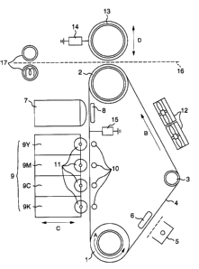
Fig. 1 is a conceptual view which shows a
color image forming device for which a color image
forming method in an embodiment of the present
invention is applied. Three rollers, that is, a drive
roller 1 which is driven by a drive power source which
is not shown, a driven roller 2 and a tension roller 3,
are arranged with their axes are extended substantially
in one and the same direction. A dielectric belt 4 is
extended being made into contact with these three
rollers. This dielectric belt 4 is used as an
electrostatic latent image recording medium. The
dielectric belt 4 is applied thereto with tension by
means of the tension roller 3. As the drive roller 1
is rotated in a direction indicated by the arrow A, the
dielectric belt 4 is driven so as to run in a direction
indicated by the arrow B. The dielectric belt 4 is
composed of at least two layers, that is, a conductive
layer and a dielectric layer, the dielectric layer
being laid on the front surface side while the
CA 02364969 2003-09-22
conductive layer is laid on the roller side. This
conductive layer is electrically connected so as to
have a potential equal to that of the three rollers.
Further, the potential of the conductive layer is
maintained at a predetermined value by means of a belt
bias voltage applying means 15.
An electric charge eliminator 5 is provided
opposing the surface of the dielectric layer of the
dielectric belt 4 running from the drive roller Z to
the tension roller. The charge eliminator 5 has a role
of previously setting the potential on the surface of
the dielectric layer of the dielectric belt 4 to a
value which is substantially equal to a desired
potential. The elimination of electric charge by the
charge eliminator 5 is controlled such that variation
in the potential on the surface of the dielectric belt
4 is held within a range which is substantially 1/10 of
a minimum potential range corresponding to a potential
difference per one gradation that is created on the
surface of the dielectric belt 4 by the recording head
7. In this embodiment, a scorotron charger is used as
the charge eliminator 5 in this embodiment, and
however, any of those other than the scorotron charge
may be used if it can effects the above-mentioned
charge elimination. For example, a metal roller is
used as the charge eliminator 5 for charge-injection in
order to set the potential on the surface of the
dielectric belt to a desired potential with a tolerance
CA 02364969 2003-09-22
9
substantially equal to the above mentioned variation.
A counter electrode 6 which is located making
contact with the rear surface of the dielectric belt 4
at a position facing the charge eliminator 5 tfirough
the intermediary of the dielectric belt 4, is
electrically connected so as to have a potential equal
to that of the conductive layer of the dielectric belt
. 4.
The recording head 7 is located opposing the
surface of the dielectric layer of the dielectric belt
4 in a part where the dielectric belt 4 runs from the
driven roller 2 to the drive roller 1. A counter
electrode 8 is located making contact with the rear
surface of the dielectric belt 4 at a position facing
the recording head 7 through the intermediary of the
dielectric belt 4. This counter electrode $ is
electrically connected so as to have a potential equal
to that of the conductive layer of the dielectric
layer.
The recording head 7 forms a latent image on
the front surface of the dielectric belt 4 in
accordance with an image signal for instructing
printing, delivered from a host side to the color image
forming device. At this time, a gradation per unit
pixel can be obtained with the use of a degree of
electric charge accumulated on the front surface of the
dielectric belt 4. As mentioned above, a minimum
potential range of electric charge accumulated on the
CA 02364969 2003-09-22
front surface of the dielectric belt 4 should be
sufficiently greater than the variation in potential on
the front surface of the dielectric belt 4, which is
obtained by charge elimination. In this embodiment,
5 the minimum potential range is set to be about 10 times
as large as the variation in potential cased by chare
elimination.
Four developing units 9 are arranged in a
row, facing the outer surface of the dielectric layer
10 of the dielectric belt 4 in a part where the belt 4
runs the driven roller 2 to the drive roller 1.
Further, the developing units 9 are laid, being nearer
to the drive roller 1 than to the recording head 7.
The developing units 9 are a yellow developing unit 9Y,
a magenta developing unit 9M and cyan developing unit
9C and a black developing unit 9K which are arranged in
the mentioned order in a direction away from a position
near to the recording head. Liquid developers having
corresponding colors are reserved in the developing
units 9, respectively. The four developing units 9 are
selectively displaceable in the direction indicated by
the arrow C so that one of them is displaced to a
predetermined developing position, depending upon a
latent image which is therefore developed. Further,
counter electrodes 10 are provided making contact with
the rear surface of the dielectric belt at positions
facing the developing units 9 through the intermediary
of the dielectric belt 4, and are electrically
CA 02364969 2003-09-22
11
connected so as to have a potential equal to that of
the conductive layer of the dielectric belt. Further,
the distance between the developing units 9 and the
developing roller 11 is preferably set to a critical
distance with which a liquid film does not break since
color mixing is caused if the distance is too short
while no liquid film can be formed if it is too long.
This critical distance varies, depending upon a
wettability between the dielectric belt 4 and the
liquid developer, and between a developing roller 11
and the liquid developer. In this embodiment, the
distance between the developing roller 11 and the
dielectric belt 4 is substantially set to be slightly
smaller than 10 ~ m. The development will be detailed
later with reference to Figs. 2 and 4.
A blower 12 serving as a drying means is
located, facing the outer surface of the dielectric
layer of the dielectric belt 4 in a part in which the
dielectric belt 4 runs from the tension roller 3 to the
driven roller 4. By driving this blower 12, a solvent
in the developer on the dielectric belt 4 is volatized
in a short time so as to obtain dried toner. In this
embodiment, although explanation has been made such
that the blower is used as the drying means, the drying
means should not limited to the blower, and any of
those which can effect volatilization of the solvent
may be used as the drying means.
A pressing roller 13 is located at a position
CA 02364969 2003-09-22
12
facing the driven roller 2 through the intermediary of
the dielectric belt 4. In the embodiment, the pressing
roller 13 serves as an electric field creating means
for pressing the dried toner particles toward the
dielectric belt 4 with the use of electric force, and
also severs as a part of a transfer means for
transferring an image in which images for different
colors including a final color are superposed with one
another, onto a final recording medium which is not
shown, However, the electric field creating means and
the transfer means may be separately provided.
The pressing roller 13 has a conductive
elastic layer on its outer surface. Further, the
pressing roller 13 is controlled so that an electric
field for pressing the dried toner particles is
generated between the pressing roller 13 and the
conductive layer of the dielectric belt 4 when the
pressing roller 13 serves as the electric field forming
means by means of a roller bias applying means 14 while
a transfer field is generated between the pressing
roller 13 and the conductive layer of the dielectric
belt 4 when the pressing roller serves as the transfer
means. Although effects by the electric field creating
means will be detailed later, when the pressing roller
13 serves as the electric field creating means, the
dried toner particles is applied with a force toward
the dielectric belt 4 due to a created electric field.
On the contrary, when the pressing roller 13 serves a
CA 02364969 2003-09-22
13
part of the transfer means, a force is applied in a
direction in which the toner particles go away from the
dielectric belt 4.
Next, explanation will be made of a method of
forming an image, according to the present invention.
At first, the charge eliminator carries our elimination
of charge, and accordingly, a predetermined potential
is maintained with a predetermined tolerance on the
front surface of the dielectric belt 4. Then a latent
image is formed on the front surface of the dielectric
belt 4 in accordance with an image signal corresponding
to a first color by the recording head 7. Then, a
developing unit 9 corresponding to this color is
displaced toward the dielectric belt 4, and after it
reaches its developing position, the development is
carried out. At this time, the development is started
at a position slightly before the developing unit 9
reaches an image zone on the dielectric belt 4, and the
development is completed after a position after it goes
across the image zone. Thus, the development can be
made without affection upon the image by a transient
condition during the formation of a liquid film. After
the development, residual electric charge on the
dielectric belt 4 is eliminated by the charge
eliminator 5 so as to set up a predetermined potential
on the front surface of the dielectric belt 4 with a
certain tolerance. Through this charge elimination, a
gradation per unit pixel can be obtained during
CA 02364969 2003-09-22
14
formation of an image corresponding to a second color.
Next, a solvent of a liquid development which
sticks to the dielectric belt 4, corresponding to the
latent image is volatized by the blower 12 as a drying
means. Should the image corresponding to the second
color be formed in a condition in which the solvent
remains, a damage to the recording head 7 or color
mixing in the developing unit 9 would be caused. This
problem can be eliminated through the drying step and
the next step of applying an electric field.
In a condition of an image on the dielectric
belt 4 after the volatilization of the solvent in the
liquid developer, the toner which has been in the form
of a bit of powder is carried on the dielectric belt 4
by a physical adhesion and a weak electrostatic force.
Accordingly, should an image corresponding to the
second color be formed, the above-mentioned problem
would be caused. This problem will be discussed in
detail later. In order to solve this problem, in this
embodiment, an electric field is effected between the
pressing roller 13 and the dielectric belt 4 so as to
press the toner particles toward the dielectric belt 4.
Since the dielectric belt 4 on which the image is
formed by the toner particles is exposed to the
electric field, the distance between the toner
particles and the distance between the toner particles
and the dielectric belt 4 becomes shorter, and
accordingly, the physical adhesion between the toner
CA 02364969 2003-09-22
particles and between the toner particles and the
dielectric belt 4 is enhanced. The thus created
electric field is set to a value less than a half of
the discharge initiating electric field of the-air
5 since it should not exceed the discharge initiating
electric field.
The above-mentioned steps are repeated before
an image corresponding to a final color is formed. For
the final color, the steps up to the drying step are
10 carried out, and the image is transferred onto a paper
sheet by a transfer means. The paper sheet is then
conveyed along a transfer path indicted by a dotted
line 16 by a conveyer means which is not shown.
In this embodiment, the drying steps for the
15 final color is carried out, and then the transfer is
carried out through thermal transfer. However, after
elimination of electric charge for the final color,
electrostatic transfer may be carried out in a wetting
condition. In this case, a transfer voltage is
maintained on the outer surface of the pressing roller
13 by a roller bias applying means 14.
Next, explanation will be made of the process
of the development with reference to Fig. 2 which is a
schematic view for explaining a developing condition
carried out between the developing unit 9 and the
dielectric belt 4. Referring to Fig. 2, a liquid film
of a liquid developer 102 is formed between the
dielectric belt 4 and the developing roller 11 provided
CA 02364969 2003-09-22
I6
in the developing unit 9. In this embodiment, when the
dielectric belt 4 runs in a direction indicated by the
arrow E, the developing roller 11 is rotated in a
direction indicated by the arrow F. A latent image 101
corresponding to the developing unit 9 is formed in
accordance with an image signal on the front surface of
the dielectric belt 4. Since a developing bias
electric field is applied between the conductive layer
of the dielectric belt 4 and the developing roller 11
in a direction indicated by the arrow G, an
electrostatic force is exerted to toner particles 104
dispersed in a solvent 103 of the liquid developer 102
in the direction indicted by the arrow G. The toner
particles 104 are also exerted thereto with an
electrostatic force from the latent image 101 on the
front surface of the dielectric belt 4. Accordingly,
if the electrostatic force exerted to the toner
particles 104 from the latent image 101 on the front
surface of the dielectric belt 4 overcomes the
electrostatic force exerted to the toner particles by
the developing bias electric field, the toner particle
104 sticks to the latent image 101 on the front surface
of the dielectric belt 4. If it is not the case, no
toner particles stick to the front surface of the
dielectric belt 4. Thus, the toner particles 104
sticks to the front surface of the dielectric belt 4
only in a part where the latent image is formed, and
accordingly, the development for the latent image can
CA 02364969 2003-09-22
17
be made.
Next, explanation will be made of the effect
obtained by pressing the toner particles against the
dielectric belt by the electric field creating means
with reference to Figs. 3a to 3d which are first
schematic views for explaining conditions of toner
particles. Fig. 3a schematically shows a condition of
a liquid developer 52 which sticks to the dielectric
belt 4 at the time when a latent image is formed and
developed on the dielectric belt 4 after electric
charge is eliminated from the dielectric belt 4, as
viewed in the direction of the section of the
dielectric belt. Since electric charge 51 is presented
in accordance with an image signal on the front surface
of the dielectric belt 4, toner particles which are
dispersed in a solvent 53 of the liquid developer 52 in
accordance with the electric charge 51 are attracted by
an electrostatic force between the toner particles and
the electric charge on the front surface of the
dielectric belt 4, and accordingly, they stick to the
front surface of the dielectric belt 4.
Next, Fig. 3b schematically shows a condition
which is obtained when the electric charge on the
dielectric belt 4 is eliminated by the charge
eliminator 5 shown in Fig. 1, as viewed in the
direction of the section of the dielectric belt.
Fig. 3c schematically shows a condition in
which the solvent 53 of the liquid developer 52 on the
CA 02364969 2003-09-22
18
dielectric belt 4 is volatized by the blower 12 as the
drying means shown in Fig. 1, and accordingly, the
dried toner particles 54 stick to the dielectric belt
4, as viewed in the direction of the section of the
dielectric belt.
Fig. 3d schematically shows a condition in
which the adhesion between the dried toner 54 on the
dielectric belt 4 and the later and the adhesion
between the toner particles 54 are enforced by an
electric field generated between the pressing roller 13
serving as the electric field creating means shown in
Fig. 1, and the conductive layer of the dielectric belt
4. In the condition after the developed image is dried
as shown in Fig. 3c, if the contacts parts between the
toner particles as indicated by 54A or between another
particles as indicated by 54B, are less, the toner
particles stick to the front surface of the dielectric
belt 4 or to other toner particles under weak adhesion.
Should a latent image corresponding to a second color
be directly formed with the use of the recording head 7
shown in Fig. l, the toner particles as indicated by
54A or 54B which are held under weak adhesion would
scatter and accordingly, a disturbance of the image or
damage to the recording head would be caused. Further,
during development, the toner particles sticking under
weak adhesion as indicated by 59A, 54B would cause
disturbance of the image, color missing or the like due
to a fluid force of a solvent in a liquid developer for
CA 02364969 2003-09-22
19
a second color.
There has been such a demand that the
sticking force between the toner particles stuck under
weak adhesion and the front surface of the dielectric
belt 4 and the sticking force between the toner
particles are enforced. According to the present
invention, the toner particles 54 is pressed against
the front surface of the dielectric belt 4 by the
above-mentioned electric field, that is, the sticking
force is enhanced by the electric field creating means
in this embodiment.
Next, explanation will be made of
superposition of different colors with reference to
Fig. 4 and Figs. 5a to 5d, in particular, in the case
of, for example, a second color.
Referring to Fig. 4 which is a schematic view
for explaining the development for the second color, a
liquid film of a liquid developer 112 for the second
color is formed between the dielectric belt 4 and the
developing roller 11. In this embodiment, when the
dielectric belt 4 runs in a direction indicated by the
arrow E, the developing roller 11 is rotated in a
direction indicated by the arrow F. The toner
particles 115 of the first color pressed against the
front surface of the dielectric belt 4 stick to the
front surface of the dielectric belt 4, corresponding
to the image signal for the first color. Further, a
latent image 111 corresponding to an image signal for
CA 02364969 2003-09-22
the second color is formed on the front surface of the
dielectric belt 4. A developing bias electric field is
applied between the conductive layer of the dielectric
belt 4 and the developing roller 11 in a direction
5 indicated by the arrow G. Since the toner particles
114 are applied thereto with an electrostatic force
from the latent image on the front surface of the
dielectric belt 4, if the electrostatic force exerted
to the toner particles from the latent image 111 on the
10 front surface of the dielectric belt 4 overcomes the
electrostatic force exerted to the toner particles 114
by the developing bias electric field, the toner
particles stick to the front surface of the toner belt
4, but it is not the case, no toner particles stick to
15 the front surface of the dielectric belt 4.
Accordingly, the toner particles stick to a part in
which the latent image 111 is formed on the front
surface of the dielectric belt 4, that is, the
development is carried out only in the part.
20 The toner particles 115 for the first color
are pressed against the front surface of the dielectric
belt 4 by the electric field creating means, the
positions of the toner particles are restrained from
being displaced under affection of the fluid force of
the solvent 113.
Figs. 5a to 5d, show process steps pressing
the toner particles against the dielectric belt 4 by
the electric field creating means during development
CA 02364969 2003-09-22
21
for the second color. Fig. 5a schematically shows such
a condition that, after the toner particles 53 for the
first color are pressed against the front surface of
the dielectric belt 4 as shown in Fig. 3d, a latent
image corresponding to an image signal for the second
color is formed and developed on the dielectric belt 4,
and accordingly, the liquid developer 62 sticks to the
dielectric belt 4, as viewed in the direction of the
section of the dielectric belt 4. Since electric
charge 61 corresponding to the image signal for the
second color is present on the front surface of the
dielectric belt 4, the toner particles 64 for the
second color which are dispersed in a solvent 63 of the
liquid developer 62, corresponding to the electric
charge 61 stick to the front surface of the dielectric
belt 4 or to the toner particles 54 for the first
color, being attracted by an electrostatic force
between the toner particles for the second color and
the electric charge 61 on the front surface of the
dielectric belt 4. Next, Fig. 5b schematically shows
such a condition that the electric charge 61 is
eliminated by the charge eliminator 5 shown in Fig. 1,
as viewed in the direction of the section of the
dielectric belt 4. Further, Fig. 5c schematically
shows such a condition that the solvent 63 of the
liquid developer 62 on the dielectric belt 4 is
volatized by the blower 12 as the drying means shown in
Fig. 1, and the thus dried toner particles 64 stick to
CA 02364969 2003-09-22
22
the dielectric belt 4 or to the toner particles 54 for
the first color, as viewed in the direction of the
section of the dielectric belt 4. Further, Fig. 5d
schematically shows such a condition that the adhesion
between the dried toner particles 64 on the dielectric
belt 4 and the latter and adhesion between the toner
particles 64 and the toner particle 54 for the first
color and between the toner particles 64 are enhanced
by an electric field generated between the pressing
roller 13 as the electric field creating means and the
conductive layer of the dielectric belt 4, as viewed in
the direction of the section of the dielectric belt 4.
After completion of the drying, toner particles as
indicated by 64A and other toner particles as indicated
by 64B stick to the front surface of the dielectric
belt 4 and to the toner particles 54 for the first
color or the other toners 64 only under a weak sticking
force. Should the latent image be developed
corresponding to the second color with the use of the
recording head 7 shown in Fig. 1 as it is, the toner
particles indicated by 64A or indicated by 64B would
scatter, causing disturbance of the image or damage to
the recording head 7. Further, during the development,
the toner particle indicated by 64A or 64B sticking
under weak adhesion causes disturbance of the image,
color mixing or the like due to a fluid force in the
liquid developer for the second color. Thus, there is
presented such a demand that the toner particles 64 are
CA 02364969 2003-09-22
23
pressed against the front surface of the dielectric
belt 4 under the above-mentioned electric field so as
to enhance the sticking force between the toner
particles 64 and the front surface of the dielectric
belt 4, and between the toner particles. This can be
carried out by the electric field creating means in
this embodiment.
Subsequent to a third color and up to a final
color, the development of the image and the pressing of
the toner particles for different colors by the
electric field creating means can be made, similar to
the steps for the second color.
As mentioned above, according to the present
invention, since different colors can be superposed
with each other on the electrostatic latent image
bearing (recording) medium without melting the toner
particles, the color image forming device can be small-
sized without lowering the printing speed. Further,
generation of extra heat can be minimized without
increasing the power to be used, thereby it is possible
to provide a color image forming device and a color
image developing method which can minimize the
generation of extra heat.
CA 02364969 2003-09-22
24
To the end, according to a first aspect of the
present invention, there is provided a color image forming
device comprising a latent image recording medium on which
a latent image is formed, a plurality of developing units
for developing the latent image with the use of liquid
developers each having at least toner particles and a
solvent, the image developed by the developing units being
formed on the recording medium, characterized by a drying
means for drying the developed image and an adhesion
enhancing means for increasing the adhesion of the toner
particles.
The adhesion enhancing means desirably applies
an electric field which can exert a force directing toward
the latent image recording medium to the toner particles
constituting an image after the solvent is evaporated, or
a force pressing the toner particles against the latent
image recording medium. The adhesion enhancing means may
be a means for applying a transcription bias. The means
for applying a transfer bias may also serve as a transfer
bias supply means in a fixing unit, for transferring and
fixing a developed image onto a recording medium.
Further, the above-mentioned image forming
device preferably incorporates a charge eliminator for
eliminating electric charge from electrostatic recording
CA 02364969 2003-09-22
medium, in order to eliminate an electric charge to a
degree by which the gradation of a latent image is not
deteriorated.
Further, according to a second aspect of the
5 present invention, there is provided a color image forming
device comprising an electrostatic latent image recording
medium for carrying thereon electrostatic images
corresponding to image signals, a plurality of developing
units for manifesting the latent images for different
10 colors with the use of liquid developers, a drier for
drying the images for different colors, developed on the
electrostatic latent image recording medium by the
developers, and an adhesion enhancing means for enhancing
adhesion of toner particles on the electrostatic latent
25 recording medium, dried by the dryer.
The adhesion enhancing means includes an
adhesion applying means which may be an electric field
generating means for generating an electric field for
pressing toner particles constituting color images and
20 dried by the drying means, toward the latent image
recording medium. This electric field generating means is
preferably a transferring means for applying a transfer
bias for transfer. An electrostatic latent image for each
color formed on the electrostatic latent image is
CA 02364969 2003-09-22
26
developed by a developing unit corresponding to the color
with the use of a liquid developer. The thus developed
image wetted with a solvent is dried by the dryer. The
dried image is exposed to the electric field which urges
toner particles forming the image toward the electrostatic
latent image recording medium, and accordingly, the image
can be formed in a stable condition on the electrostatic
latent image recording medium. Even though a next latent
image is formed and is then developed with a second color
on the electrostatic latent image recording medium on
which the stable image has been formed, the next image can
be stably formed without increasing the power used for the
device.
Further, the color image forming device
according to the present invention, preferably
incorporates a transfer means for transferring, in a
batch, a final image which is formed on the electrostatic
latent image recording medium and which is developed by
superposing different color images with one another, onto
a final recording medium. This transfer means preferably
includes at least one heating means or one pressuring
means for fixing the image simultaneously with the
transfer.
CA 02364969 2003-09-22
27
Further, the color image forming device
according to the present invention may have an electric
charge eliminating means which preferably eliminates
electric charge within a range in which local chare
potential difference on the electrostatic latent image
recording medium does not deteriorate the gradation of a
latent image formed on the latent image recording medium
by the recording head.
Further, the color image forming device
according to the present invention preferably uses a
liquid developer in which the density of toner dispersed
therein is from 5 to 35 0.
According to the present invention, there is
provided a color image forming method characterized by the
steps of forming an electrostatic latent image
corresponding to an image signal, on an electrostatic
latent image recording medium, developing the latent image
formed on the electrostatic latent image recording medium
with the use of a developer reserved in a developing unit,
drying the thus manifested image on the developing latent
image recording medium, and enhancing the adhesion of
toner particles which constitute the dried image.
In the color imager forming method according to
the present invention, the step of enhancing the adhesion
CA 02364969 2003-09-22
28
of the toner particles preferably conveys the
electrostatic latent image recording medium formed thereon
the electrostatic latent image into an electric field in
which the toner particles forming the dried image is
pressed toward the electrostatic latent image recording
medium.
According to the present invention, images for
different colors which have been obtained by developing
latent images can be stably laminated with one another
with no color mixing. In the case of superposing
developers, that is, images having different colors of
toner, with one another, when an image having a second
color is formed directly over a dried toner image having a
first color, there is caused a problem which should be
solved. Detailed description will be made of formation of
a second latent image on an electrostatic latent image
recording medium on which toner having a first color is
merely dried in the form of an image, with the use of a
recording head. In this condition, the dried toner on the
electrostatic latent image recording medium is attracted
toward the recording head by an electric field which is
applied between the electrostatic latent image recording
medium and the recording head in order to form a new
latent image, resulting in a damage to the recording head.
CA 02364969 2003-09-22
29
In order to prevent occurrence of such a problem,
according to the present invention, before the second
image is formed over the image formed by the dried toner,
the toner is pressed toward the electrostatic latent image
recording medium by the electric field. Due to the above-
mentioned pressing, the physical adhesion between the
toner and the electrostatic latent image recording medium
and in the toner can be enhanced, and accordingly, there
can be prevented the scattering of toner from the
recording head by an electric field, color mixing in the
developing part, and the like, thereby it is possible to
carry out superposition of the toner images on the
electrostatic latent image recording medium only through
drying of the liquid developer without curing of toner
(melting or solidifying of toner particles).
Further, in the color image forming method
according to the present invention, the above-mentioned
steps are repeated by several times for different colors,
except a final color in the developing unit, and an image
for this final color which is developed on the
electrostatic latent image recording medium, and is then
dried, may be transferred onto a final recording medium.
Further, in the color image forming method
according to the present invention, the above-mentioned
CA 02364969 2003-09-22
steps are repeated by several times for different colors,
except a final color in the developing unit, and an image
for this final color which is developed on the
electrostatic latent image recording medium, may be
5 transferred onto a final recording medium without being
dried.