Note: Descriptions are shown in the official language in which they were submitted.
CA 02365183 2001-08-24
- WO 00/57822 PCT/US00/02063
INFLATABLE THERMAL BLANKET
WITH A MULTILAYER SHEET
BACKGROUND OF THE INVENTION
1. Field of the Invention
This invention relates generally to inflatable thermal blankets and, more
particularly, to an inflatable thermal blanket with a multilayer sheet in
which, after
use, a layer of the multilayer sheet can be detached, thereby enabling the
inflatable
thermal blanket to be reused.
2. Description of the Related Art
It often is necessary to control a person's body temperature using means
external to the person. For example, it is important to keep a person warm
during
surgery and to warm the person post-operatively to reduce the risk of
hypothermia. 60-70% of surgical persons will experience hypothermia during
surgery, if not treated. Many studies have been published showing the
detrimental
effects of hypothermia that occur during surgery. Such effects include a
higher
incidence of infections, more bleeding, more adverse cardiac events, higher
death
rates, slower recovery and longer hospitalizations. One means of preventing or
treating hypothermia is the inflatable thermal blanket.
Inflatable thermal blankets have been in clinical use for the past ten years.
Such a blanket may be inflated with cooled or warmed air and deployed over a
person in need of thermal management where it bathes the person in a flow of
cool or warm air. Persons needing thermal management include accidental
hypothermia victims, persons with fever and persons undergoing surgery.
Numerous research studies have shown that inflatable thermal blankets provide
a
highly effective and safe mode of thermal management.
In one use, an inflatable thermal blanket is inflated with warm air and
placed adjacent a person. Warm air is expelled through a surface of the device
that faces the person, creating a warmed environment about the person, thereby
reducing and even reversing the transfer of heat from the person to the
SUBSTITUTE SHEET (RULE 26)
CA 02365183 2004-04-26
-2-
environment. Inflatable thermal blankets are provided for generalized and
specialized uses, for which various inflatable structures have been developed.
See, for example, U.S. Patent Nos. 4,572,188; 5,300,101; 5,300,102; 5,324,320;
5,336,250 and 5,350,417 assigned to Augustine Medical, Inc. With the
introduction
of the BAIR HUGGER' family of inflatable thermal blankets by Augustine Medi-
cal, Inc. , clinicians have been enabled to provide safe and effective thermal
therapy
to persons in a number of clinical settings, including surgery and recovery.
An inflatable thermal blanket typically includes a surface through which the
inflating medium is expelled. Such a surface may include apertures formed in
it by a
manufacturing process, or may comprise an air-permeable material, for example.
The blanket is deployed with the surface facing the person and the thermally-
controlled air which inflates the device is exhausted from the blanket,
through the
surface, toward the person. The temperature of the thermally controlled air
can be
precisely controlled in order to warm or cool a person. The majority of
inflatable
thermal blankets sold today are disposable "single use" products made of
polymeric
films and non-woven material. Extreme pressure to control costs has forced
many
health care providers to carefully examine their use of such disposables. In
some
cases, providers may reuse "single use" blankets which have been in contact
with a
previous person's skin and bodily fluids. There is no suitable way to clean
and
sterilize these "single use" blankets and therefore this practice can transmit
infec-
tion from one person to another.
In response to the trend toward reuse of medical products, some manufactur-
ers are now providing inflatable thermal blankets made of durable materials
which
can be cleaned and sterilized between uses. These blankets also appeal to the
providers who believe that disposables are not friendly to the environment.
How-
ever, reusable inflatable thermal blankets also have several draw-backs.
First, they
are expensive. Second, their durability is severely limited by the high
temperatures
and strong detergents necessary to clean and sterilize them. Finally, the
detergents
themselves are environmentally unfriendly.
From the discussion above, it should be apparent that there is a need for an
inflatable thermal blanket that can be safely and economically used multiple
times
CA 02365183 2001-08-24
- WO 00/57822 PCT/US00/02063
3
on one or more persons without requiring sterilization between uses. The
present
invention satisfies this need.
SUMMARY OF THE INVENTION
Broadly, the present invention concerns an inflatable thermal blanket with
a multilayer sheet providing a surface through which air is transferred from
the
blanket toward a person. Presently, once an inflatable thermal blanket has
been
used on a person, this surface may be contaminated. Consequently, the blanket
must be cleaned and sterilized or discarded. The advantage of a multilayer
sheet
is that the layers in the plurality of layers that make up the multilayer
sheet may be
detached from the sheet one or more at a time and discarded. So, following use
of
the inflatable thermal blanket, the contaminated layer or layers may be
removed to
render the inflatable thermal blanket ready for use again.
In an example that embodies, but which does not limit, the invention, an
inflatable thermal blanket with a multilayer base sheet comprises an
inflatable
structure formed by attaching a first sheet to a second sheet. An inflation
port is
provided in the inflatable structure for admitting a stream of thermally-
controlled
air (e.g., heated or cooled air) into the inflatable structure. The multilayer
sheet is
assembled from a plurality of sheets releasably attached together. The
multilayer
sheet is attached to the second sheet of the inflatable structure. Finally, a
plurality
of air passageways through the second sheet and the multilayer sheet allow the
thermally-controlled air to flow through the inflatable structure. In a
preferred
embodiment, one or more layers of the multilayer sheet can be removed at one
time without detaching the rest of the plurality of sheets. In this way,
contaminated sheets can be removed individually, or multiply, and the
inflatable
thermal blanket can be reused.
Other features and advantages of the present invention should be apparent
from the following description of the preferred embodiments, which illustrate,
by
way of example, the principles of the invention.
SUBSTITUTE SHEET (RULE 26)
CA 02365183 2001-08-24
- WO 00/57822 PCT/US00/02063
4
BRIEF DESCRIPTION OF THE DRAWING
The nature, objects, and advantages of the invention will become more
apparent to those skilled in the art after considering the following detailed
description in connection with the accompanying drawings, in which like
reference numerals designate like parts throughout, wherein:
Figure 1 is a perspective view showing one embodiment of the present
invention of an inflatable thermal blanket with a multilayer sheet disposed on
a
base sheet;
Figure 2 is an exploded view of Figure 1 showing the inflatable structure
and the multiple layers of the sheet;
Figure 3 is a perspective view similar to Figure 1 showing another
embodiment of the inflatable structure;
Figure 4 is a cross-sectional view of Figure 1 prior to the attachment of the
multiple layers to the inflatable structure;
Figure 5 is a cross-sectional view of Figure 1 showing the attachment of
the multiple layers to the inflatable structure;
Figure 6 is another exploded view of Figure 1 showing the multiple layers
laminated before attachment to the inflatable structure;
Figure. 7 is a sectional view 7-7 of Figure 6 showing one embodiment of
the multiple layers with a melted hole;
Figure 8 is a sectional view 8-8 of Figure 6 showing another assembly
embodiment of the multiple layers with a punched hole;
Figure 9 and Figure 10 are cross-sectional views of Figure 3 showing
another embodiment of the inflatable structure; and
Figure 11 is a cross-sectional view similar to Figure 10 showing an
alternate structure for the multiple layers.
DESCRIPTION OF THE PREFERRED EMBODIMENTS
The figures show an inflatable thermal blanket in an inflated condition for
clarity and ease of understanding. It is to be understood however, that the
invention applies to inflatable thermal blankets in an uninflated condition as
well.
SUBSTITUTE SHEET (RULE 26)
CA 02365183 2001-08-24
- WO 00/57822 PCT/LTS00/02063
The invention concerns a unitary, integral structure with a plurality of
layers that may be detached one-by-one from the unitary integral structure.
The
structure is referred to as a "multilayer sheet". As the following discussion
will
reveal, each layer of the multilayer is best embodied as a sheet. However, in
order
5 to avoid confusing each sheet of a layer with the multilayer sheet, the
individual
sheets of the multilayer sheet will be referred to in the description and
claims as
"layers", with the understanding that "layer" may mean "sheet".
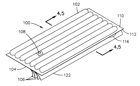
Figure 1 is an instructive illustration of the present invention, in the form
of an inflatable thermal blanket 100. The inflatable thermal blanket 100
includes
an inflatable structure 102 and a multilayer sheet 104. The multilayer sheet
104 is
made from a plurality of sheets or layers 106 assembled together in such a
manner
as to make each layer detachable from a neighboring layer. The inflatable
thermal
blanket 100 also includes an inflation port 108 located in the inflatable
structure
102, which may be connected to a tube (not shown) leading to an external
heater/blower unit (not shown). Together, the tube and blower unit provide
pressurized thermally-controlled air (for either heating or cooling) to
inflate the
thermal blanket 100.
Figure 2 is an exploded view of Figure 1 showing the inflatable structure
102 and the multilayer sheet 104. The inflatable structure 102 of the thermal
blanket 100 includes a first sheet 110 and a second sheet 112 (see also
Figures 4
and 5). The sheet 110 is preferably made of a polymeric film material. The
second sheet 112 may be made of a polymeric film, a fibrous or non-woven
material or a combination of these materials. The first sheet 110 and second
sheet
112 are joined at one or more locations to form the inflatable structure 102.
For
example, the sheets may be joined along a substantially continuous seam near
the
peripheries of the sheets, but other configurations are possible. The location
of
such a seam with reference to the first sheet 110 is indicated by reference
numeral
114. The first sheet 110 and second sheet 112 may also be joined together at
one
or more locations 118 within the peripheral seam at 114. These additional
locations 118 help to direct the air flow and prevent the inflatable structure
102
from blowing up like a beach ball. Figure 3 illustrates another inflatable
structure
103. The inflatable structure 103 is similar to inflatable structure 102 but
the
SUBSTITUTE SHEET (RULE 26)
CA 02365183 2001-08-24
WO 00/57822 PCT/US00/02063
6
locations 118 are a plurality of stake points, forming a quilt-like structure.
These
embodiments are but two examples of some of the shapes and structures that the
inflatable thermal blanket can be formed into. Many other, but nevertheless
equivalent variations are possible.
Referring again to Figure 2, the inflatable thermal blanket 100 includes
one or more additional layers 106 that are joined together to form the
multilayer
sheet 104. The additional layers 106 include a layer 122, which is adjacent to
the
second sheet 112 (i.e., the layer closest to the inflatable structure).
Preferably, the
additional layers 106 are made of a non-woven material that is hydrophobic and
therefore fluid repelling or a non-woven material that has been "waterproofed"
by
laminating it to a polymeric film layer. Alternately, the additional layers
106 may
be made of a polymeric film, fibrous materials, woven or non-woven materials
or
a combination of these materials.
For the inflatable thermal blanket 100 to heat or cool a person, it must be
attached to a unit that provides a stream of warmed or cooled air. The
inflation
port 108 allows the temperature controlled stream of air to enter the
inflatable
structure 102, the usual connection being an air hose. At least one surface of
the
thermal blanket 100, the air is released through a plurality of air
passageways,
which allow the air to flow from the thermal blanket 100 toward a person (not
shown).
Figure 4 shows a cross-sectional view of the inflatable structure 102 when
inflated, with the multilayer sheet 104 unattached. The inflatable structure
102 is
assembled with the first sheet 110 and the second sheet 112 joined together
along
a substantially continuous seam at 114. As is evident, when the structure 102
is
inflated it manifests parallel flattened tubes. Also shown is the multilayer
sheet
104 assembled with the plurality of layers 106, one of which may be designated
as a "closest" layer 122. It is contemplated by the inventors that the closest
layer
122 of the multilayer sheet 104 could also serve as the second sheet 112 by
directly attaching the first sheet 110 to the closest layer 122.
Figure 5 is a cross-sectional view of the thermal blanket 100 showing the
inflatable structure 102 assembled with the multilayer sheet 104. As discussed
above, pressurized air flows out of the thermal blanket 100 through the second
SUBSTITUTE SHEET (RULE 26)
CA 02365183 2001-08-24
WO 00/57822 PCT/US00/02063
7
sheet 112. In the second sheet 112, a plurality of air passageways 124 are
formed
to allow air to flow from the inflatable structure 102. In addition to these
air
passageways there are also air passageways 124 through the multilayer sheet
104.
Preferably these air passageways 124 are created through all of the layers 106
by
forming the air passageways 124 through all of the layers 106 of the sheet 104
at
once. Alternately, the air passageways 124 may be inherent if the layers 106
are
made of a non-woven or woven material (i.e., a porous material). Finally, air
passageways 124 may be formed in the individual layers 106 before stacking.
Figure 6 is an exploded view similar to Figure 2 showing the layers 106
assembled into the multilayer sheet 104. In one embodiment, the layers 106 are
joined together at 134. However, the layers are separated at a corner 136 to
allow
the separation of an individual layer 106 when required (described in more
detail
below).
Figures 7 and 8 show alternate methods of forming the air passageways
124 in the multilayer sheet 104. In the preferred embodiment, the air
passageways 124 may be formed by melting and/or by punching in such a manner
as to join the layers 106 together at the perimeter of each hole. If a
passageway is
created by melting for example, as shown in Figure 7, the melted material
joins
each layer 106 to the next at the passageway, forming the multilayer sheet
104. If
the passageway 124 is created by punching, as shown in Figure 8, the design of
the punch and die can be optimized so as to entangle fibers from the adjacent
layers 106 of material, resulting in a mechanical "bond" 128 between the
layers
106 forming the multilayer sheet 104. Further, a combination of punching and
melting may be utilized. The advantage of this, design is that the bonds
joining the
layers 106 at the perimeters of the passageways 124 assure that the
corresponding
passageways 124 in each layer 106 are oriented with one another. Precisely
aligning the passageways 124 in the layers 106 reduces the total resistance to
air
flow by providing a direct air flow path 126 through all of the layers 106.
This
direct air flow path 126 is advantageous because it provides more air flow
through
the inflatable thermal blanket. Alternately, if the layers 106 are
"breathable" (i.e.,
formed of porous material) and do not require holes punched in them for air
flow,
the layers 106 may be joined (adhesively or thermally, for example) together
at
SUBSTITUTE SHEET (RULE 26)
CA 02365183 2001-08-24
- WO 00/57822 PCT/US00/02063
8
multiple locations 130 across their surfaces or at their peripheries or at
combinations of these locations (see Figure 11).
Refernng again to Figures 4 and 5, when attaching the multilayer sheet
104 to the inflatable structure 102, the "closest" layer 122 is placed
proximate the
second sheet 112 and attached at multiple locations 138. For example, the
closest
layer 122 may be adhesively attached at 138 to the second sheet 112.
Alternately,
the closest layer 122 may be thermally bonded at 138 to the second sheet 112.
In
another embodiment, the closest layer 122 is removeably attached to the second
sheet 112 at 138 with a hook-and-eye material. Preferably the closest layer
122 is
attached to the second sheet 112 at multiple locations 138 across its surface.
Finally, since the inflatable thermal blanket with a multilayer sheet is
reusable in multiple successive deployments, each layer 106 must be detachable
from an adjacent layer 106. In the preferred embodiment, the bottom-most layer
106 (i.e., the layer 106 furthest from layer 122) can be separated (i.e.,
detached)
from the adjacent layer by tearing the relatively weak thermal and/or
entangled
fiber bond 128 at the periphery of each passageway 124. This allows the
bottom-most layer of the thermal blanket 100, which was in contact with a
person
in a first deployment and therefore may have been contaminated, to be
discarded
after use. The remaining thermal blanket 100 is fully functional and clean for
the
next deployment. The closest layer 122 may also be detachable from the second
sheet 112. In that way, once all the layers 106 of the multilayer sheet 104
have
been used, layer 122 is detached from the second sheet 112 and another
multilayer
base sheet 104 can be attached and the inflatable thermal blanket can be used
in
the same manner as previously described.
Optionally, for user convenience and cleanliness, a corner of the multilayer
sheet 104 can have the individual layers 106 accessible for the clinician or
user to
remove, one layer at a time. Optionally, a pull-tab 140 may be attached to
each
layer 106 for additional ease of use (see Figure 2). The pull-tab 140 aids the
clinician in removing only the bottom-most layer, leaving the remaining
blanket
100 intact.
Figures 9 and 10 illustrate a possible alternate embodiment of the
inflatable structure 103 of Figures 3, 4 and S with the multilayer sheet 104.
As
SUBSTITUTE SHEET (RULE 26)
CA 02365183 2001-08-24
- WO 00/57822 PCT/LTS00/02063
9
may be appreciated with inspection of these figures, the first and second
sheets are
joined in such a way as to form parallel fully rounded tubes when the
structure
103 is inflated.
Figure 11 shows an alternate embodiment inflatable structure 103 along
with an alternate embodiment of the multilayer sheet 105. In this embodiment,
the plurality of layers 106 are constructed from a porous or "breathable"
material
which allows the air to flow from the inflatable structure through the layers
of
"breathable" material and onto the person. In this construction, the
multilayer
sheet 105 is constructed from a plurality of layers 106 attached together at a
plurality of locations 130. The multilayer sheet 105 may be attached to
inflatable
structure 103 by adhesive, heat bond or hook-and-eye material as described
previously. The layers 106 may also be joined together around the periphery
132.
In one manufacturing embodiment, the layers 106 may be bonded together
to form the multilayer sheet 104. In the preferred embodiment , the multilayer
sheet 104 is assembled before joining the closest layer 122 to the second
sheet
layer 112. The preferred material for the layers 106 is a non-woven polyester
or
polypropylene which has been laminated with a layer of polypropylene or
polyethylene film. Unwinding multiple rolls of this material simultaneously,
two
or more sheets of this material are layered onto one another in a web-type
process.
The layers 106 are joined together and the passageways 124 are punched through
the layers before the individual multilayer sheets are cut from the web.
Preferably
the passageways 124 are melted and/or punched through all of the layers at
once,
simultaneously creating passageways 124 and the bonds between the layers 106
at
the edge of the holes (as described previously). The passageways 124 may be
melted by piercing the layers with a many small hot spikes. Alternately the
passageways 124 may be created by melting the material with a laser, jets of
hot
air or other suitable means.
The layers 106 may be joined using a male plain or serrated punch, cutting
onto an anvil material or into a female die. The punches serve two purposes.
First
they create the passageways 124 through the plural layers 106. Second, the
serrations serve to entangle the fibers of the materials 128 of the layers
106, at the
periphery of the passageways 124 (see Figure 8). This creates a mechanical
SUBSTITUTE SHEET (R ULE 26)
CA 02365183 2001-08-24
- WO 00/57822 PCT/US00/02063
"bond" between the layers and serves to align the passageways 124 in the
layers
106. The shape and size of the punches and the serrations may be varied to
achieve various levels of bonding. Finally, the punches, anvil or die may be
heated to partially or completely melt the material at the periphery of the
hole. In
S this case, the level of heat may be adjusted to control the strength of the
bonding
between the layers.
Preferably, the layers 106 are bonded together into the multilayer sheet
104 and the air passageways 124 are created before the closest layer 122 is
bonded
to the second sheet 112 of the previously assembled inflatable structure 102.
The
10 closest layer 122 and the second sheet 112 are adhesively bonded together
at
multiple locations 138 across their surfaces. The adhesive bond may or may not
be detachable between the closest layer 122 and the second sheet 112.
Alternately
this bond 138 may be created by thermally melting the materials of the
adjacent
layers. Finally, both the inflatable structure 102 and the multilayer sheet
104 are
1 S cut from the web simultaneously forming the thermal blanket 100.
For cost and environmental reasons, the thin material of the bottom layer
minimizes the amount of material being discarded thereby making a practical,
safe, effective, economical and environmentally friendly multiple use forced
air
thermal blanket.
The description and illustrations thus far have placed a single multilayer
sheet on the bottom surface of an inflatable thermal blanket. This is not
intended
to, and should not, so limit the practice of the invention. As those skilled
in the art
will appreciate, air may be expelled through surfaces other than the bottom
surface of an inflatable thermal blanket. For example, in certain tubular
structures, air is expelled through a side surface, or through a side portion
of a
generally cylindrical surface. In other, pad-like, structures, air may be
expelled
through a top surface. Moreover, air may be expelled through more than one
surface. A multilayer sheet, or a plurality of multilayer sheets according to
this
invention, may be attached to one or more such surfaces of an inflatable
thermal
blanket.
SUBSTITUTE SHEET (RULE 26)
CA 02365183 2001-08-24
WO 00/57822 PCT/US00/02063
11
While the invention herein disclosed has been described by means of
specific embodiments and applications thereof, numerous modifications and
variations could be made thereto by those skilled in the art without departing
from
the scope of the invention set forth in the claims.
WE CLAIM
SUBSTITUTE SHEET (RULE 26)