Language selection

Search

Patent 2365357 Summary

Third-party information liability

Some of the information on this Web page has been provided by external sources. The Government of Canada is not responsible for the accuracy, reliability or currency of the information supplied by external sources. Users wishing to rely upon this information should consult directly with the source of the information. Content provided by external sources is not subject to official languages, privacy and accessibility requirements.

Claims and Abstract availability

Any discrepancies in the text and image of the Claims and Abstract are due to differing posting times. Text of the Claims and Abstract are posted:

  • At the time the application is open to public inspection;
  • At the time of issue of the patent (grant).
(12) Patent: (11) CA 2365357
(54) English Title: SHORT-ARC HIGH-PRESSURE DISCHARGE LAMP FOR DIGITAL PROJECTION TECHNOLOGIES
(54) French Title: LAMPE A DECHARGE HAUTE PRESSION A ARC COURT POUR TECHNIQUES NUMERIQUES DE PROJECTION
Status: Deemed expired
Bibliographic Data
(51) International Patent Classification (IPC):
  • H01J 61/86 (2006.01)
  • H01J 61/073 (2006.01)
  • H01J 61/16 (2006.01)
(72) Inventors :
  • MEHR, THOMAS (Germany)
  • SEEDORF, RALF (Germany)
(73) Owners :
  • PATENT-TREUHAND-GESELLSCHAFT FUER ELEKTRISCHE GLUEHLAMPEN MBH (Germany)
(71) Applicants :
  • PATENT-TREUHAND-GESELLSCHAFT FUER ELEKTRISCHE GLUEHLAMPEN MBH (Germany)
(74) Agent: SMART & BIGGAR LLP
(74) Associate agent:
(45) Issued: 2010-10-26
(22) Filed Date: 2001-12-18
(41) Open to Public Inspection: 2002-06-20
Examination requested: 2006-07-20
Availability of licence: N/A
(25) Language of filing: English

Patent Cooperation Treaty (PCT): No

(30) Application Priority Data:
Application No. Country/Territory Date
100 63 938.0 Germany 2000-12-20

Abstracts

English Abstract


In a short-arc high-pressure discharge lamp (1) with a
xenon fill for digital projection purposes, the
separation L in mm of the two mutually facing end
sections (6a, 8c) of the cathode (6) and the anode (8)
when the lamp is hot is given by the relationship
0.8×P <= L <= 1×P+1, where P is the lamp power in kW.
Further, the diameter D of the circular-cylindrical
middle section (8a) of the anode (8) in mm obeys the
relationship D >= 2.1×L+10.


French Abstract

Dans une lampe à décharge haute pression à arc court (1) remplie de xénon pour des projections numériques, l'écart L en mm des deux sections d'extrémité face à face (6a, 8c) de la cathode (6) et de l'anode (8) lorsque la lampe est chaude est exprimé par la relation 0,8.fois.P <= L <= 1.fois.P+1, où P représente la puissance de la lampe en kW. En outre, le diamètre D de la section cylindrique circulaire centrale (8a) de l'anode (8), en mm, est exprimé par la relation D >= 2.1.fois.L+10.

Claims

Note: Claims are shown in the official language in which they were submitted.


CLAIMS:


1. A short-arc high-pressure discharge lamp with a discharge vessel
which, besides a cathode and an anode that are situated opposite each other,
contains a fill comprising at least xenon, wherein the cathode has a conical
end
section facing the anode and the anode has a circular-cylindrical middle
section
and a frustoconical end section facing the cathode, and the high-pressure
discharge lamp for use in digital projection technologies has the following
further
features:

- the separation L in mm of the two mutually facing end sections of
the cathode and the anode when the lamp is hot is given by the relationship
0.8xP <= L <= 1xP+1,

where P is the lamp power in kW

- the diameter D of the circular-cylindrical middle section of the
anode in mm is given by the relationship

D >= 2.1 xL+10,

where L is the separation of the mutually facing end sections of the
cathode and the anode in mm,

wherein the frustoconical end section of the anode, which faces the
cathode, has a plateau AP with a diameter in mm that satisfies the
relationship
1.8xL-1 <= AP <= 1.8xL+1,

where L is the separation of the mutually facing end sections of the cathode
and
the anode in mm.


2. The short-arc high-pressure discharge lamp according to claim 1,
wherein the tip of the conical end section of the cathode is designed as a
hemisphere, wherein the radius R of the hemisphere in mm satisfies the
relationship


6

0.12xP+0.1 <= R <= 0.12xP+0.5,
with P being the lamp power in kW.


3. The short-arc high-pressure discharge lamp according to claim 2,
wherein the conical end section of the cathode has a vertex angle a of between
36
and 44°.


4. The short-arc high-pressure discharge lamp according to claim 1,
wherein the frustoconical end section of the anode, which faces the cathode,
has
a vertex angle .beta. of between 90 and 105°.


5. A method of operating a short-arc high-pressure discharge lamp
according to any one of claims 1 to 4, wherein the short-arc high-pressure
discharge lamp is operated

- at a rated power P of between 0 and 5.5 kW, with a lamp current I
in A of the relationship

22xP+38 <= 1 <= 22xP+65

- and at a rated power P of between 5.5 and 12 kW, with a lamp
current I in A of the relationship

10xP+100 <= I <= 22xP+65.


Description

Note: Descriptions are shown in the official language in which they were submitted.


CA 02365357 2009-11-18
66498-143

1
Short-Arc High-Pressure Discharge Lamp for Digital Projection Technologies
Technical field

The invention is based on a short-arc high-pressure discharge lamp
with a discharge vessel which, besides a cathode and an anode that are
situated
opposite each other, contains a fill comprising at least xenon, wherein the
cathode
has a conical end section facing the anode and the anode has a circular-
cylindrical middle section and a frustoconical end section facing the cathode,
and
the high-pressure discharge lamp for use in digital projection technologies.
It
involves, in particular, a short-arc high-pressure discharge lamp with a xenon
fill,
lo as is used in cinema projection.

Prior Art

The known xenon short-arc lamps for projection purposes were
optimized for arc lengths and electrode geometries which are ideal for
35 to 70 mm film projection. The picture diagonals of these films lie in the
range
of between 28 and 60 mm. If such standard lamps are used in modern digital
projection systems with DMD, DLP, LCD and D-ILA technology, then owing to the
mismatch between the lamp and the optical system, a great deal of light is
lost
and does not reach the screen. This lost light is converted into heat in the
projector and leads to additional problems. To date, it has been possible to
2o resolve this problem only by a higher lamp power, which then requires
greater
outlay on cooling, an optimized mirror design, which places great demands on
the
accuracy and the simulation tasks, and additional double mirrors, which in
turn
entail cooling problems in the reflector volume.

Background of the Invention

It is an object of embodiments of the present invention to provide a
short-arc lamp with a xenon fill, which permits optimum focusing of the light
onto
small cross sections of between 10 and 25 mm, corresponding to the diagonals
of
the integrators that are used in digital projection technologies (DMD, DLP,
LCD
and D-ILA)..


CA 02365357 2009-11-18
66498-143

2
The lamp is advantageously operated at a rated power P of between
0 and 5.5 kW, with a lamp current I in A of the relationship 22xP+38 <_ 1:5
22xP+65
and at a rated power P of between 5.5 and 12 kW, with a lamp current I in A of
the
relationship 10xP+100 s I <_ 22xP+65.

By setting the separation L in mm of the two mutually facing end
sections of the anode and the cathode when the lamp is hot, according to the
relationship 0.8xP <_ L <_ 1xP+1, where P is the lamp power in kW, optimum
illumination of the picture window is achieved. With longer arc lengths, the
efficiency of the system, i.e. the ratio of the output light flux to the
incoming power,
lo is significantly degraded. If the anode-cathode separation is shorter than
in the
relationship, then the life of the lamp is unacceptably reduced.

The stronger heating of the front surface of the anode (anode
plateau) for shorter arcs also requires adaptation of the anode geometry. For
instance, the diameter D of the anode in mm must satisfy the relationship
D >_ 2.1 xL+10, where L is the separation of the mutually facing end sections
of the
anode and the cathode in mm when the lamp is hot.

Advantageously, for optimum luminous efficiency with a long life, the
frustoconical end section of the anode, which faces the cathode, should have a
plateau AP with a diameter in mm that satisfies the relationship
1.8xL-1 s AP <_ 1.8xL+1, where L is again the separation of the mutually
facing
ends of the anode and the cathode in mm when hot. When the anode plateau
diameter falls below this, strong erosion (cratering) on the anode plateau
leads to
a shorter life. In the case of an anode plateau that is larger than specified
by the
relationship, the system effiency is degraded because of shadowing.

For optimum distribution of the light density throughout the life, the
tip of the conical end section of the cathode is further advantageously
designed as
a hemisphere, wherein the radius R of the hemisphere in


CA 02365357 2009-04-27
66498-143

3
mm satisfies the relationship 0.12xP+0.1 <_ R:5 0.12xP+0.5, with P being the
lamp
power in kW. Larger diameters of the hemisphere result in a lower light
density,
and smaller diameters lead to enhanced cathode burn-off.

Advantageously, the conical end section of the cathode has a vertex
angle a of between 36 and 440. Further, the frustoconical end section of the
anode has, for optimum operation, a vertex angle a of between 90 and 105 .
More pointed geometries lead to stronger burn-off of the electrode tips, while
blunter geometries cause a high degree of shadowing in the projector.

For optimum operation with a sufficiently high efficiency (lumen/W),
and an acceptable decrease in the light flux over the life of the lamp, the
lamp
should be operated, at a rated power P of between 0 and 5.5 kW, with a lamp
current I in A of the relationship 22xP+38 <_ 1:5 22xP+65 and, at a rated
power P of
between 5.5 and 12 kW, with a lamp current I in A of the relationship
1 OxP+1 00 5 15 22xP+65. While weaker currents reduce the luminous efficiency
in the system, the cathode erosion increases with stronger currents and the
maintenance falls below acceptable values.

In one broad aspect, there is provided a short-arc high-pressure
discharge lamp with a discharge vessel which, besides a cathode and an anode
that are situated opposite each other, contains a fill comprising at least
xenon,
wherein the cathode has a conical end section facing the anode and the anode
has a circular-cylindrical middle section and a frustoconical end section
facing the
cathode, and the high-pressure discharge lamp for use in digital projection
technologies has the following further features: the separation L in mm of the
two
mutually facing end sections of the cathode and the anode when the lamp is hot
is
given by the relationship 0.8xP 5 L:5 1 xP+1, where P is the lamp power in kW
the
diameter D of the circular-cylindrical middle section of the anode in mm is
given by
the relationship D <_ 2.1xL+10, where L is the separation of the mutually
facing end
sections of the cathode and the anode in mm, wherein the frustoconical end
section of the anode, which faces the cathode, has a plateau AP with a
diameter
in mm that satisfies the relationship 1.8xL-1 5 AP 51.8xL+1, where L is the


CA 02365357 2009-04-27
66498-143

3a
separation of the mutually facing end sections of the cathode and the anode in
mm.

Description of the drawings

With the following figures, the invention will be explained in more
detail in relation to an exemplary embodiment:

Figure 1 shows a short-arc high-pressure discharge lamp according
to the invention,

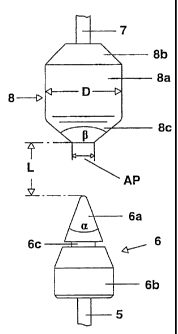
Figure 2 shows, in an enlarged representation, the electrode
arrangement of the short-arc high-pressure discharge lamp according to Figure
1.
Description of the Preferred Embodiment

Figure 1 represents a short-arc high-pressure discharge lamp 1
according to the invention with a Xe fill. The lamp 1, with a power
consumption of
3000 W, consists of a rotationally symmetric light bulb 2 made of quartz
glass, the
two ends of which are each fitted with a lamp shaft 3, 4, also made of quartz
glass. A


= CA 02365357 2001-12-18

4 -
tungsten electrode rod 5, the inner end of which
supports a cathode 6, is fused hermetically into one of
the shafts, the shaft 3. A tungsten electrode rod 7,
the inner end of which has an anode 8 fastened to it,
is likewise fused hermetically into the other lamp
shaft 4. Base systems 9, 10 for support and electrical
connection are fitted to the outer ends of the
electrode shafts 3, 4.
As can be seen in Figure 2, the cathode 6 is
composed of a conical end section 6a, which faces the
anode 8, and an end section 6b which faces the
electrode rod 5 and has a circular-cylindrical
subsection as well as a frustoconical subsection, a
section 6c of smaller diameter, which is likewise
circular-cylindrical and is referred to as a heat
damming groove being located between these two sections
6a, 6b. The tip of the conical end section 6a, which
faces the anode 8 and has a vertex angle a of 40 , is
designed as a hemisphere with a radius R of 0.6 mm.
The anode 8 consists of a circular-cylindrical
middle section 8a with a diameter D of 22 mm and two
frustoconical end sections 8b, 8c, which respectively
face the cathode 6 and the electrode rod 7. The
frustoconical end section 8c that faces the cathode 6
has a plateau AP with a diameter of 6 mm. All the
sections of the two electrodes 6, 8 are made of
tungsten.
The two electrodes 6, 7 are fitted opposite one
another, in alignment with the axis of the lamp bulb 2,
in such a way that the electrode separation, or arc
length, is 3.5 mm when the lamp is hot.
When this lamp is used in a digital projection
system, an improvement of up to 50% can be achieved
compared with conventional short-arc high-pressure
discharge lamps with a xenon fill.

Representative Drawing
A single figure which represents the drawing illustrating the invention.
Administrative Status

For a clearer understanding of the status of the application/patent presented on this page, the site Disclaimer , as well as the definitions for Patent , Administrative Status , Maintenance Fee  and Payment History  should be consulted.

Administrative Status

Title Date
Forecasted Issue Date 2010-10-26
(22) Filed 2001-12-18
(41) Open to Public Inspection 2002-06-20
Examination Requested 2006-07-20
(45) Issued 2010-10-26
Deemed Expired 2019-12-18

Abandonment History

There is no abandonment history.

Payment History

Fee Type Anniversary Year Due Date Amount Paid Paid Date
Registration of a document - section 124 $100.00 2001-12-18
Application Fee $300.00 2001-12-18
Maintenance Fee - Application - New Act 2 2003-12-18 $100.00 2003-12-15
Maintenance Fee - Application - New Act 3 2004-12-20 $100.00 2004-12-01
Maintenance Fee - Application - New Act 4 2005-12-19 $100.00 2005-12-01
Request for Examination $800.00 2006-07-20
Maintenance Fee - Application - New Act 5 2006-12-18 $200.00 2006-11-09
Maintenance Fee - Application - New Act 6 2007-12-18 $200.00 2007-11-14
Maintenance Fee - Application - New Act 7 2008-12-18 $200.00 2008-11-06
Maintenance Fee - Application - New Act 8 2009-12-18 $200.00 2009-11-17
Final Fee $300.00 2010-08-16
Maintenance Fee - Patent - New Act 9 2010-12-20 $200.00 2010-11-04
Maintenance Fee - Patent - New Act 10 2011-12-19 $250.00 2011-11-03
Maintenance Fee - Patent - New Act 11 2012-12-18 $250.00 2012-12-03
Maintenance Fee - Patent - New Act 12 2013-12-18 $250.00 2013-12-09
Maintenance Fee - Patent - New Act 13 2014-12-18 $250.00 2014-12-08
Maintenance Fee - Patent - New Act 14 2015-12-18 $250.00 2015-12-07
Maintenance Fee - Patent - New Act 15 2016-12-19 $450.00 2016-12-05
Maintenance Fee - Patent - New Act 16 2017-12-18 $450.00 2017-12-04
Maintenance Fee - Patent - New Act 17 2018-12-18 $450.00 2018-12-10
Owners on Record

Note: Records showing the ownership history in alphabetical order.

Current Owners on Record
PATENT-TREUHAND-GESELLSCHAFT FUER ELEKTRISCHE GLUEHLAMPEN MBH
Past Owners on Record
MEHR, THOMAS
SEEDORF, RALF
Past Owners that do not appear in the "Owners on Record" listing will appear in other documentation within the application.
Documents

To view selected files, please enter reCAPTCHA code :


To view images, click a link in the Document Description column. To download the documents, select one or more checkboxes in the first column and then click the "Download Selected in PDF format (Zip Archive)" or the "Download Selected as Single PDF" button.

List of published and non-published patent-specific documents on the CPD .

If you have any difficulty accessing content, you can call the Client Service Centre at 1-866-997-1936 or send them an e-mail at CIPO Client Service Centre.


Document
Description 
Date
(yyyy-mm-dd) 
Number of pages   Size of Image (KB) 
Drawings 2001-12-18 2 17
Claims 2001-12-18 2 68
Description 2009-11-18 5 210
Abstract 2001-12-18 1 16
Cover Page 2002-06-21 1 30
Description 2001-12-18 4 188
Representative Drawing 2002-02-21 1 3
Description 2009-04-15 5 216
Claims 2009-04-15 2 56
Representative Drawing 2010-10-04 1 4
Cover Page 2010-10-04 1 32
Assignment 2001-12-18 3 126
Prosecution-Amendment 2006-07-20 1 43
Prosecution-Amendment 2006-08-03 1 39
Prosecution-Amendment 2008-11-05 3 85
Prosecution-Amendment 2009-04-27 7 254
Prosecution-Amendment 2009-09-21 2 37
Prosecution-Amendment 2009-11-18 4 139
Correspondence 2010-08-16 1 43