Note: Descriptions are shown in the official language in which they were submitted.
W001/63079 PCTIEP01 /02020
Title: Device for adjusting the height of a slide rail
Description
This invention relates to a device for adjusting the height of a slide rail.
This
invention relates in particular to a device for adjusting th height of a slide
rail which
is concealed in a profile.
By way of example, slide rails are used in doors that have an automatic door
closer
system. In such an application, a slide that is connected with ~ c!oor panel
by means
of a lever mechanism slides in the slide rail. When the door i~. c~pe~ed, the
slide
moves in the slide rail and the door panel, after it h.as beer owned, is then
closed
to again automatically, for example, by means of a spring force tl'~~t acts on
the lever
mechanism. The slide in the slide rail then slides back into its initial
position.
Slide rails are generally installed in tie upper area of the coor game or are
attached
to the door. To achieve the most esthetically pleasing appearance possible,
the slide
rails are generally located inside the doer frame profile so that toey are not
visible.
15 Depending on the customer's wishes, however, a wide va~~ety of door frame
profiles
with a wide variety of accessories exist which differ, am~na other things, in
terms of
their height. Because the slide rail on the door frame profile is located on
the
underside of the door frame profile, depending on the height ~f the door frame
profile
either different designs of slide rails with a height that c~~~~esponds to the
door frame
2o profile or complex and expensive substructure or railbed elements are
necessary,
and must be located between the wall-side area of the pre"i~e and the slide
rail.
The object of the invention is therefore tc provide a ~!e~rice o adjust the
height of a
slide rail that has a simple structure, is easy and economical ~;~ manufacture
and
makes it possible to adjust the height of the slide rail to meet i~;~vidual
requirements.
CA 02365422 2001-10-22
.,K:~" ' yy,.'-~ :~~,~ ;
W001 /63079 PCTIEP01 /02020
_2_
The invention teaches that this object is accomplished by tl'ae futures
disclosed in
Claims 1 and 2. The device for the cor..tinuous or progressive height
adjustment of a
slide rail thereby has a threaded sleeve that has a first fewr.ale thread.
There is also a
threaded bush that has a male thread. The threaded bush can be screwed into
the
first female thread of the threaded s'eeve to adjust the height er vertical
position of
the slide rail. When assembled, the slide rail is in contact with the threaded
bush, i.e.
it can be located on the exposed side of the threaded bush. T he invention
thereby
teaches that it is possible to set the desired positio~ of tine Aide rail by
means of the
threaded sleeve and the threaded bush located in ~t. The invention therefore
teaches
Zo a simple and economical device to adjust the height of a slide rail.
The dependent claims disclose additional configurations of the teaching of the
invention.
The device to adjust the height is preferably a bolt element. This bolt
element can be
used to fix the relative position, i.e. the adjustable heigir~i; between the
threaded
sleeve and the threaded bush.
The threaded sleeve preferably has a second female thread the diameter of
which is
smaller than that of the first female tnread. By means of the second female
thread, it
is possible to fix the positions of the threaded slee°,~e and of the
threaded bush in
relation to each other. This fixing of ~he threaded sleeve and the threaded
bush in
2o relation to each other is preferably achieved by a bolt eiVment that can be
screwed
into the second female thread. In this manner, the slide rail can also be
fastened to
the threaded bush.
The threaded bush, on the end facing the slide rail, also has an area with an
enlarged diameter. The invention teaches that the siide~ r ai'i can be easily
adjusted on
the threaded bush and there is a large contact surface between the slide rail
and the
threaded bush. The invention also makes it possible. a~iona other things, to
fix the
slide rail in position by means of the bolt element.
CA 02365422 2001-10-22
.... k~4,,. tY
,yfi~:. ym" y~..~' y.;
W001163079 PCTIEP01102020
_3_
The threaded sleeve preferably has a male tf~read. Tf;e threaded sleeve can
thereby
be easily connected with the door frame profile. In. this case. the threaded
sleeve can
be screwed into an opening in the profile that is provided with a thread, or
can be
inserted through an opening provided in the profile and secured by means of a
nut. It
is also possible, however, to fasten the threaded sleeve dire~~t'.y in the
wall area.
In a second preferred embodiment of the invention, a fastening receptacle can
also
be used which does not require any rastening by ~reas?s of a r?;~t. This
fastening
receptacle has, next to or in addition to a central dart that has a female
thread for
connection with the threaded bush, shaped brackets which are connected with
the
to profile by means of screws, rivets etc.
To achieve an aesthetically appropriate appearance, the device to adjust the
height
of the slide rail is located in a cavity of a profile. The device to adjust
the height of a
slide rail is therefore not externally visible.
The device for the continuous adjustment of the height of a slide rail is
preferably
15 located in a profile that has at feast one depression. Th;s depression
makes possible,
among other things, smaller adjustments between t!~e slide rain and the door
panel,
whereby the position of the slide rail with respect to the doo° panel
is set to a lesser
extent by means of the device to adjust the height of the slice rail. In this
case, the
cross section of the profile can be somewhat deformed ir1 the vicinity of the
2 o depression.
The invention thus also makes possible a slide rail with a height adjustment
device
as claimed by the invention it which standardized gudde ~~iis can be used for
different profiles; and the height of the slide rails can be
~~°ratinuously adjusted by
means of the height adjustment device taught by the invention. Among other
things,
25 significant cost advantages are achieved as a result of ~"A Ymal!er number
of parts
required. Slide rails of different heights can also be used.
CA 02365422 2001-10-22
". ;~, G..
'a: ..
W001163079 PCT/EP01 /02020
The invention is explained in greater detail below on the basis of the
exemplary
embodiments that are illustrated schematically in the accompanying drawings,
in
which:
Figure 1: Is a side view of a height adjustment device as claimed by the
invention
with reference to a first exemplary embodiment.
Figure 2: Is a sectional view of a threaded bush as claimed by the invention.
Figure 3: Is a sectional view of a threaded sleeve as claimed by the
invention.
Figure 4: Is a sectional view of a height adjustment devicE with reference to
a
second exemplary embodiment of this inven'ion.
to Figure 5: Is a sectional view along Line A-A ir: Figure 4.
Figure 6: Is a sectional view of a height adjustment c~ev~ce with reference to
a
third exemplary embodiment.
Figure 7: Is a fastening receptacle in a plan view.
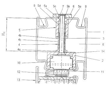
As illustrated in Figure 1, the height adjustment device taught by the
invention and as
15 illustrated in a first exemplary embodiment has a threaaed sleeve 5 and a
threaded
bush 4. For purposes of illustration, the threaded sleeve 5 and'the threaded
bush 4
are illustrated on an enlarged scale in Figures 3 and 2 respect~~ely.
As illustrated in Figure 2, the threaded bush 4 has a cylindrical main body 4
and a
contact area 4a. The contact area 4a has a larger diameaer than the
cylindrical main
2o body 4b. As illustrated in Figure 1, when the device is ina;alled, the
contact area 4a
is directly adjacent to a slide rail 2. The s6ide rail 2 car thereby' be
fastened in a
stable fashion to a plurality of threaded bushes 4. On the threaded bush 4
there is
CA 02365422 2001-10-22
<'v ~;~..~;: ;
W001163079 PCTlEP01 /02020
also a male thread 4c
As shown in Figure 3, the threaded sleeve 5 has a firsu cyl~r~drical area 5a
and a
second cylindrical area 5b. The second cylindrical area 5b thereby has a
smaller
diameter than the first cylindrical area 5a. On the second wylindrical area 5b
there is
s a male thread 5c The threaded sleeve 5, along its :,enter a;~is O-O, also
has a
passage hole 7, whereby the passage hole has two different diameters. In this
case,
there is a first female thread 5d on the first cylindr~va' aria 5a and a
second female
thread 5e on the second cylindrical area 5b.
As shown in Figure 1, the threaded bush 4 and the threaded sleeve 5 are
located in
to a cavity 8 of a profile 1. The profile 1 can have, for exar;~ple, c. ~ the
side in its upper
area, two depressions 9 and an opening 7. The secon~;,y';ndricai area 5b with
the
smaller diameter is inserted ~hrough the opening 7 and is secured by means of
a nut
6 on the profile 1.
As illustrated in Figure 1, the threaded sleeve 4 with its r-sale thread 4c is
partly
15 screwed into the first female thread 5d of the threaded sleeve 5. In this
case, the
threaded bush 4 is screwed into the threaded slee~~e 5 until the slide rail 2
can be
located at a predetermined height. The slide rail is then; 'aster~ed ro the
height
adjustment device by means of a bolt 3 that is inser<eu th,' ugh an opening 14
in the
slide rail 2, by screwing the bolt 3 into the second femal:: thread 5e of the
threaded
2o sleeve 5 (See Figure 1). The distance between the contact area 14 and the
inside of
the profile thereby has a height H,.
A slide 10 is then located in the slide 2; in the manner of the prior art, and
can be
moved along the slide rail 2. The slide 10 is connected :o a door panel 13 by
means
of a stud 11 of a lever mechanism 12.
25 The slide rail height adjustment device claimed by the '°~~ventidr~
therefore makes it
possible, even after a door has been installed, to adi~ist the: height of the
slide rail
CA 02365422 2001-10-22
~~r~.wf.
CA 02365422 2001-10-22 '~ -' "
,i~,.°.
W001/63079 PCT/EP01 /02020
_5
2 by screwing the threaded bush 4 farther into the th~ea~ed sleeve 5 or by
unscrewing it farther out of the threaded sleeve 5. Even after ~ door has been
installed, it is thereby possible to at feast partly compensate for uneven
spots in a
floor, for example, by changing the position of the slide rai( and to adjust
the opening
s or closing characteristic of the door.
The depressions 9 provided on the profile 1 also make it possible to vary the
position
of the slide rail 2 with respect to the profile 1 by tightening the s;,rew 3
without
thereby damaging the profile 1 in the exposed area. it is also possible to
compensate
for relatively small tolerances, inaccuracies, or une~r~en spots.
to The following description relates to the slide rail height adjustment
device illustrated
in Figures 4 and 5, as it is used on a profile other Than the one illustrated
in Figure 1.
As illustrated in Figure 4, the profile 1 has a lower height than the profile
illustrated in
Figure 1. Therefore the height adjustment device is set o a height H2. As
shown in
Figure 4, the threaded bush 4 's screwed into the threaded sleeve 5
practically all the
15 way, whereby only the contact area 4a of the threaded hustv 4 projects out
of the
threaded sleeve 5. The slide rail 2 is again fastened with a s~re~.w 3 to the
second
female thread 5a of the threaded sleeve 5. The profile 1 is fastened with the
side that
has the depression 9 or on or in a wall snot shown).
Corresponding to the exemplary embodiment illustrated in Figure 1, on the
2o exemplary embodiment illustrated in Figure 4 the slide rail 2 is also
fastened with a
screw 3 to the height adjustment device. Because the height H~ is relatively
small,
only a short screw 3 is used. As shown in the sectional illustration in Figure
5, the
threaded bush 4 is realized so that it is cylindrical, while the threaded
sleeve 5 is
hexagonal. In this case; however, any other exter!~al c~nfgurations of the
threaded
25 bush 4 and of the threaded sleeve 5 can also be used.
~a,:
W
W001/63079 PCT/EP01 /02020
_7_
In summary, the invention teaches a slide rail height adustmeot device that
comprises a threaded sleeve 5 that has a first female thread 5d and a threaded
bush
4 that has a male thread 4c. To adjust the height ~?f the slide ra; 2, the
threaded
bush 4 can be screwed into the first fer~iale thread 5d of tl-.e thraaded
sleeve 5. The
height adjustment device is thereby located between the side rail 2 and a wall-
side
frame element of a door. When installed, the slide rail 2 can eye located on
the
exposed end of the threaded bush 4, i.e. the end that's locateC facing the end
connected with the threaded sleeve 5.
In an additional embodiment of the i;wention, as iil~<sti~atEd ir. o-~gures 6
and 7, there
io is a fastening receptacle 15 which replaces the t~s~neaded sieve 5. The
fastening
receptacle 15 is realized so that there a;~ a continuous fe~naie thread 16
into which a
threaded bush 20 is screwed. On account of the male thread 4c of the threaded
bush
20, in connection with the female thread 16, a cor~tin;~ou5 height adjustment
of the
slide rail 2 inside the profile 1 is possible, whereby the slide rail 2 is
fastened by
means of the screws 3 with a thread 19 contained in the Threaded bush 20. For
better contact with the threaded bush 20, there is a contac' area 4a on the
threaded
bush 20. In the brackets 18 that extend laterally from a~ intermediate piece
that is
not illustrated in any further detail and carries the thread 16, there are
countersunk
borings 17. By means of these countersunk bcrinas ':' 7, the fastening
receptacle 15
2 o is fastened inside the profile 1 using screws, rivets etc.
The slide rail 2 illustrated in Figure 6 is taller than the side °ails
illustrated in the
preceding illustrations: It is thereby possible fo install dif~ere~~t slide
rails 2 and to
adjust their height continuously.
To achieve a second hold or mounting of the guide rail, the s ;yews 3 are
realized so
2s that they contain a captive device that guarantees a corre~,t seating.
CA 02365422 2001-10-22
. . . ~ ~~
W001/63079 PCTIEP01102020
_g .
Nomenclature
1 Profile
2 Slide rail
3 Screw
4 Threaded bush
4a Contact area
4b Cylindrical main body
4c Male thread
5 Threaded sleeve
l0 5a First cylindrical area
5b Second cylindrical area
5c Male thread
5d First female thread
5e Second female thread
6 Nut
7 Opening
8 Cavity
9 Depression
10 Slide
2 0 11 Stud
12 Lever mechanism
13 Door panel
14 Opening
15 Fastening receptacle
16 Female thread
17 Countersunk boring
18 Brackets
19 Female thread
20 Threaded bush
CA 02365422 2001-10-22