Note: Descriptions are shown in the official language in which they were submitted.
CA 02365521 2006-03-13
SYSTEMS FOR DELIVERING LIQUIFIED NATURAL 6AS TO AN ENGINE
CONTRACTUAL ORI&IN OF THE INVENTION
The United States has rights in this invention pursuant to
Contract No. DE-AC07-94IDI3223 between the U.S. Department of Energy
and Lockheed Martin Idaho Technologies Company.
15 BACKGROUND OF THE INVENTION
Field of the Invention
The present invention relates to fuel delivery systems and,
more specifically, systems for delivering liquefied natural gas from
a fuel tank to an engine.
zo
Present State of the Art
The increasing output of automobile emissions and the
decreasing supply of oil reserves has motivated the search for
alternative motor vehicle fuels. One alternative fuel is natural
25 gas. Natural gas is clean burning and can be stored in a dense,
high energy liquid form. Liquefying natural gas is accomplished by
cooling the natural gas to a cryogenic temperature, typically below
-260' F, which condenses the gas into a liquid. Working with and
keeping natural gas at a cryogenic temperature, however, creates
30 inherent problems. Furthermore, natural gas, prior to combustion,
is a harmful greenhouse gas. As such, it is important that the
escape of any natural gas be minimi2ed to prevent increased damage
to the atmosphere.
In one approach to using natural gas in automobiles, the
35 natural gas is initially stored in large tanks at refueling
stations. ~ The large tanks maintain the fuel at a cryogenic
CA 02365521 2001-09-25
-WO 00/37847 PCT/US98/27231
2
temperature so as to keep the natural gas in a dense liquid state.
Smaller insulated fuel tanks are located within the automobiles and
can be f i 11 ed wi th the 1 i qui fi ed natural gas at a refuel i ng stati on
.
As discussed above, it is desirable to store the naturel gas in a
liquified state. It is also beneficial, however, to have the
automobile fuel tank sufficiently pressurized so that the fuel
therein will automatically flow to the vehicle engine. Although a
pump can be used to deliver the fuel to the engine, use of a pump
requires energy. Furthermore, pumping natural gas at cryogenic
temperatures has been found problematic.
In one approach to obtaining the desired pressure within the
automobile fuel tank, systems have been incorporated into refueling
stations which warm the liquified natural gas as it is pumped into
the automobile fuel tank. By heating the liquified natural gas to
a desired temperature, a portion of the liquified natural gas
vaporizes within the fuel tank to produce the desired pressure. The
pressure created within the fuel tank as a result of warming the
fuel is call "saturation pressure". Although this process achieves
the desired objective, it also produces several problems.
For example, the systems for heating the natural gas at the
refueling station are time consuming and expensive to operate and
build. Furthermore, as a result of warming the natural gas; less
natural gas can be stored within the fuel tank. In addition, since
all of the natural gas that is pumped into the automobile fuel tank
is heated, the fuel must be used relatively quickly to prevent
having to vent any of the natural gas to the atmosphere. That is,
although the automobile fuel tank is insulated, once the liquified
natural gas is pumped therein, the fuel begins to slowly warm
towards an equilibrium with the outside temperature. As the fuel
warms, the pressure within the tank increases. Once the tank
reaches a control pressure, a pressure relief valve is opened
allowing a portion of the natural gas to escape into the atmosphere,
thereby decreasing the internal pressure. The time period that a
tank can hol d natural gas wi thout havi ng to vent i s cal 1 ed the "hol d
time." As previously discussed, releasing natural gas into the
atmosphere is both wasteful and potentially harmful.
CA 02365521 2001-09-25
-WO 00/37847 PCT/US98/27231
3
In contrast, if the natural gas is consumed too quickly, the
pressure within the fuel tank can drop below the required operating
pressure. As liquefied natural gas is consumed, the volume of the
vapor holding portion of the fuel tank is increased. As this volume
increases, a portion of the liquefied natural gas is vaporized to
fill the space within the fuel tank. Vaporization of natural gas
is an endothermic process which absorbs heat. Accordingly, as the
natural gas within the fuel tank is vaporized, the temperature and
thus pressure within the fuel tank decreases. If liquefied natural
gas is consumed too quickly, the pressure will drop below the
operating pressure.
In an alternative approach to pressurizing the automobile fuel
tank, a heater is directly coupled with the automobile fuel tank for
heating the liquefied natural gas therein. The problem with this
approach is that it takes both time and energy to heat the fuel
within the fuel tank. Furthermore, the same problem exists of
having to use the natural gas relatively quickly to prevent having
to vent portions of the natural gas to the atmosphere.
Other problems in conventional liquefied natural gas systems
relate to the lines extending from the fuel tank to the engine.
Many of the prior art systems require the use of electronic
switches, solenoids, and computers to operate them. The use of such
electronics is expensive, increases the complexity of the system,
decreases the reliability of the system, and consumes large amounts
of energy.
The same problems as discussed above for vehicles are also
applicable to using natural gas to run engines that are not vehicle
related.
OBJECTS AND BRIEF SUMMARY OF THE INVENTION
Accordingly, it is an object of the present invention to
provide improved fuel delivery systems for liquefied natural gas.
Another object of the present invention is to provide improved
systems as above which do not require the liquefied natural gas to
be warmed as it is transferred from a refueling facility to a fuel
tank for operating an engine.
CA 02365521 2001-09-25
-WO 00/37847 PCT/US98/27231
4
Yet another object of the present invention is to provide
systems as above which do not require all of the liquid natural gas
disposed within the fuel tank to be warmed therein.
Still another object of the present invention is to provide
systems as above which significantly increase the hold time of the
liquified natural gas in the fuel tank.
Another object of the present invention is to provide improved
systems as above which maintain a desired pressure within the fuel
tank substantially independent of the fuel consumption rate.
Yet another object of the present invention is to provide
systems as above which enable relatively quick pressurization of the
fuel tank holding the liquid natural gas.
Finally, another object of the present invention to provide
improved systems as above which provide fuel lines extending from
the fuel tank to the engine which do not require the use of
electronic switches, solenoids or computers to function.
To achieve the foregoing objects, and in accordance with the
invention as embodied and broadly described herein, a fuel delivery
system is provided for operation with an engine. The engine can be
mounted to a vehicle or be stationary, for example, the engine can
be used in a generator or air conditioning system. The fluid
delivery system includes an insulated fuel tank configured to
receive liquid natural gas at cryogenic temperatures, preferably
below -220° F. The fuel tank bounds a chamber which includes a
liquid holding portion for holding liquified natural gas and a vapor
holding portion for holding vaporized natural gas. A vapor conduit
extends from the vapor holding portion of the fuel tank to an
economizer valve. A liquid conduit extends from the liquid holding
portion of the fuel tank to the economizer valve. A transition
conduit extends from the economizer valve to a vaporizer.
The economizer valve is configured to operate in one of two
positions depending on the pressure within the vapor holding portion
of the fuel tank. When pressure within the vapor holding portion
of the fuel tank is below a select pressure, the economizer valve
facilitates the flow of the liquid natural gas from the fuel tank
to the vaporizer. When the pressure within the vapor holding
portion of the fuel tank exceeds the select pressure, the economizer
CA 02365521 2001-09-25
-WO 00/37847 PCT/US98/27231
val ve b1 ocks the fl ow of 1 e qui d natural gas and face 1 e tates the fl ow
of the vaporized natural gas from the fuel tank to the vaporizer.
Once sufficient vaporized natural gas has been removed from the fuel
tank to drop the pressure therein below the select pressure, the
5 economizer valve again facilitates the flow of the liquid natural
gas from the fuel tank to the vaporizer.
The vaporizer is heated with coolant from the engine. As
liquefied natural gas is passed through the vaporizer, the elevated
temperature causes the liquefied natural gas to flash into a vapor.
A delivery conduit extends from the vaporizer to the engine for
delivering the vaporized fuel thereto. A return conduit having a
check valve coupled therewith extends from the delivery conduit to
the vapor holding portion of the fuel tank. Feeding of the
vaporized natural gas from the return conduit to the vapor holding
portion of the fuel tank functions to pressure the fuel tank.
It is desirable to keep the liquid natural gas within the fuel
tank at the lowest economical temperature. This is typically in a
range between about -220°F to about -240°F. At these
temperatures,
however, there is insufficient saturation pressure within the vapor
holding portion of the fuel tank to drive the liquid natural gas
from the fuel tank to the engine. Until such time that the liquid
natural gas warms up from the outside environment to a point that
it produces the required saturation pressure, the vaporized natural
gas feeding from the return conduit to the vapor holding portion of
the fuel tank functions to create the required pressure to operate
the system.
To enable effective pressurization of the fuel tank using the
return conduit, the vaporizer must be positioned a required distance
below the surface of the liquefied natural gas in the fuel tank.
Specifically, the head between the surface level of the liquefied
natural gas and the point in the vaporizer where the liquefied
natural gas is vaporized must be sufficiently large to create a
required pressure on the vaporized natural gas leaving the
vaporizer. This required pressure must be greater than the
summation of the pressure losses on the natural gas as it passes
from the fuel tank through the economizer valve, vaporizer, and back
to the fuel tank. As a practical matter, to enable operation of the
CA 02365521 2001-09-25
WO 00/37847 PCT/US98/27231
6
engine at low levels of fuel within the fuel tank, the vaporizer
needs to be positioned below the elevation of the fuel tank.
The above system has several advantages over prior art
systems. For example, in the present inventive system the liquid
natural gas within the fuel tank can be maintained at its lowest
possible temperature. As a result, it is not necessary to
incorporate systems for warming the fuel as it is transferred from
a refueling facility or for warming the fuel within the fuel tank.
Furthermore, since the fuel is maintained at its low cryogenic
temperature, the hold time for the fuel tank is much longer than
conventional systems. In addition, the present system can
continually regulate the pressure within the fuel tank independent
of the consumption rate. Finally, the system can be operated in a
passive configuration which does not require the use of electronic
solenoids, switches, or computers to run.
These and other objects, features, and advantages of the
present invention will become more fully apparent from the following
description and appended claims, or may be learned by the practice
of the invention as set forth hereinafter.
BRIEF DESCRIPTION OF THE DRAWINGS
In order that the manner in which the above-recited and other
advantages and objects of the invention are obtained, a more
particular description of the invention briefly described above will
be rendered by reference to specific embodiments thereof which are
illustrated in the appended drawings. Understanding that these
drawings depict only typical embodiments of the invention and are
not therefore to be considered to be limiting of its scope, the
invention will be described and explained with additional
specificity and detail through the use of the accompanying drawings
in which:
Figure 1 is a perspective view of a vehicle incorporating an
inventive fuel delivery system;
Figure 2 is a schematic representation of the fuel delivery
system incorporated into the vehicle in Figure 1;
Figure 3 is a cross-sectional front view of an economizer
valve used in the fuel delivery system shown in Figure 2;
CA 02365521 2001-09-25
WO~ 00/37847 PCT/US98/27231
7
Figure 4 is a schematic representation of an alternative
embodiment of the fuel delivery system shown in Figure 2;
Figure 5 is a cross-sectional front view of the economizer
valve used in the fuel delivery system shown in Figure 4; and
Figures 6-12 are schematic representations of alternative
embodiments of the fuel delivery system shown in Figure 2.
DETAILED DESCRIPTION OF THE PREFERRED EMBODIMENTS
Depicted in Figure 1 is one embodiment of a vehicle 10
incorporating features of the present invention. As used in the
specification and appended claims, the term "vehicle" is defined to
mean any motorized vehicle. By way of example and not by
limitation, the term "vehicle" includes cars, pickup trucks, cargo
trucks, buses, trains, aircraft, tractors, construction vehicles,
off-road equipment, farming vehicles, and helicopters. Vehicle 10
is shown having a chassis 12 with a fuel tank 14 mounted thereon.
The term "chassis" as used in the specification and appended claims
is intended to broadly include the frame and/or body of the vehicle.
In alternative embodiments, the inventive fuel delivery system
as disclosed herein can be used in situations other than on
vehicles. For example, the inventive fuel delivery systems can be
used with engines relating to compressors, generators, heating and
air conditioning systems, and virtually any other system where an
engine is required.
Fuel tank 14 is insulated, preferably by having a vacuum
barrier, and is configured to receive and retain liquid natural gas
at cryogenic temperatures. Specifically, it is preferred that fuel
tank 14 be able to receive liquid natural gas at temperatures below
-220° F. Fuel tank 14 is filled through an inlet 16. The term
"natural gas" as used in the specification and appended claims is
bodily intended to include all hydrocarbon gases that exist in a
gaseous state at ambient conditions. By way of example and not by
limitation, natural gas includes methane, ethane, propane, butane,
and pentane.
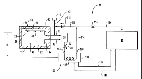
Depicted in Figure 2 is a schematic representation of one
embodiment of a fuel delivery system 18 that can be incorporated
into vehicle 10. As depicted in Figure 2, fuel tank 14 comprises
CA 02365521 2001-09-25
WO_00/37847 PCT/US98/27231
8
a liquid holding portion 20 for holding liquefied natural gas 22
and a vapor hol de ng porti on 24 for hol de ng vapori zed natural gas 26.
Li qui d hol de ng porti on 20 and vapor hol de ng porti on 24 are separated
by the surface of liquefied natural gas 22 defined by dotted line
28. The volume of liquid holding portion 20 and vapor holding
portion 24 vary inversely depending on the volume of liquefied
natural gas 22 within tank 14. That is, as liquefied natural gas
22 is consumed, surface 28 of liquefied natural gas 22 lowers,
thereby decreasing the volume of liquid holding portion 20 and
increasing the volume of vapor holding portion 24.
Tank 14 is filled with liquefied natural gas 22 by passing
liquefied natural gas 22 through inlet 16 and into a filling conduit
42. Filling conduit 42 is fluid coupled with a vapor conduit 32
having a first end 34 disposed within vapor holding portion 24 and
an opposed second end 36 fluid coupled to an economizer valve 38.
Mounted at first end 34 of vapor conduit 32 are a plurality of spray
nozzles 40. As a result of relative pressures, liquefied natural
gas 22 entering vapor conduit 32 from filling conduit 42 travels to
first end 34 where it is sprayed into tank 14 through nozzles 40.
Nozzles 40 serve a unique purpose. Under normal operating
conditions, once vehicle 10 has run for a sufficient period of time
to substantially empty fuel tank 14 of liquefied natural gas 22, the
remaining vaporized natural gas 26 within fuel tank 14 is at a
relatively high saturation pressure. This is because the remaining
natural gas within fuel tank 14 has been warmed by the outside
environment during operation. During refueling, as the cold
liquefied natural gas is sprayed into fuel tank 14 over the
vaporized natural gas therein, the vaporized natural gas is cooled
and condensed, thereby reducing the saturation pressure. As a
result, fuel tank 14 can be filed quickly and to a much greater
extent without having to vent vaporized natural gas into the
atmosphere. There are of course a variety of single or multiple
spray nozzles that can be used. Furthermore, various dripping or
other mechanisms can be used to help disperse the liquefied natural
gas over the vaporized natural gas within fuel tank 14.
CA 02365521 2001-09-25
Wa OU/37847 PCT/US98/27231
9
In one embodiment of the present invention, means are provided
for delivering natural gas from fuel tank 14 to an engine 30.
Engine 30 is likewise mounted to chassis 12 of vehicle 10. In more
specific embodiments, means are provided for passively delivering
the natural gas from fuel tank 14 to engine 30 while automatically
and passively maintaining a pressure within a predetermined range
within vapor holding portion 24 of fuel tank 14. As used in the
specification and appended claims, the term "passively" defines a
system that is self-regulating without the use of electronically
actuated flow controlling devices such as solenoids or other valves
or switches.
By way of example of the above means and not by limitation,
vapor conduit 32 extends from vapor holding portion 24 of fuel tank
14 to economizer valve 38, as discussed above. Similarly, a liquid
conduit 44 has a first end 46 positioned within liquid holding
portion 20 of fuel tank 14 and an opposing second end 48 fluid
coupl ed to economi zer val ve 38. An open i ng at f i rst end 46 of 1 i qui d
conduit 44 enables liquid natural gas 22 to travel through liquid
conduit 44 to economizer valve 38.
The present invention also includes control means for
automatically withdrawing a select natural gas chosen from either
liquified natural gas 22 or vaporized natural gas 26 from fuel tank
14 based on the pressure within fuel tank 14. By way of example and
not by limitation, depicted in Figure 3 is one embodiment of
economizer valve 38. Economizer valve 38 includes a housing 50
having an interior surface 51 bounding an elongated chamber 52.
Chamber 52 extends from a bottom end 54 to a top end 56.
Longitudinally disposed within chamber 52 is a rod 60. Rod 60 also
has a bottom end 62 and an opposing top end 64. Extending between
top end 64 of rod 60 and housing 50 is a resiliently compressible
spring 66. Radially projecting out at bottom end 62 of rod 60 is
an annular seal 68. Radially inwardly projecting from interior
surface 51 around bottom end 62 of rod 60 is a circular flange 96
having an opening 97 extending therethrough. Flange 96 is configured
such that when seal 68 is biased thereagainst, opening 97 is sealed
closed.
CA 02365521 2001-09-25
- WO 00/37847 PCT/US98/27231
Extending across chamber 52 and sealed against rod 60 and
interior surface 51 are three distinct flexible diaphragms which
divide chamber 52 into four isolated compartments. Specifically,
a flexible first diaphragm 74 bounds a first compartment 76
5 extending between first diaphragm 74 and top end 56 of compartment
52. First compartment 76 houses spring 66 and communicates to the
exterior through an opening 58. An isolated second compartment 78
is positioned between first diaphragm 74 and a flexible second
diaphragm 80. A third compartment 82 is formed between second
10 diaphragm 80 and a flexible third diaphragm 84. Finally, a fourth
compartment 86 is bounded between third diaphragm 84 and bottom end
54 of chamber 52.
Vapor conduit 32 extends through housing 50 and communicates
with second compartment 78. A bypass conduit 88 extends from vapor
conduit 32 to third compartment 82. A check valve 90 is positioned
within bypass conduit 88. A transition conduit 92 extends through
housing 50 from third compartment 82 to the exterior of economizer
valve 38. Liquid conduit 44 extends through housing 50 and
communicate with fourth compartment 86. A bypass conduit 94 extends
from fourth compartment 86, at a side of flange 96 opposite liquid
conduit 44, to transition conduit 92.
Economizer valve 38 is configured to automatically operate in
one of two positions for withdrawing either vaporized natural gas
26 from fuel tank 14 or liquefied natural gas 22 from fuel tank 14.
The determi nati on of whi ch of the two gas forms e s removed from fuel
tank 14 depends on the pressure within vapor holding portion 24.
That is, economizer valve 38 moves between one of the two positions
when a select pressure is reached within vapor holding portion 24.
The select pressure is manually set and can vary depending on the
intended use and system parameters. The select pressure is
typically in a range between about 40 psi to about 140 psi, with
about 60 psi to about 100 psi being preferred and about 20 psi to
about 80 psi being more preferred.
By way of example, when the pressure within vapor holding
portion 24 is below the select pressure, liquefied natural gas 22
flows through supply conduit 44 into fourth compartment 86, through
openi ng 97 e n fl ange 96, and through bypass condui t 94 where e t
CA 02365521 2001-09-25
WQ X0/37847 PCT/US98/27231
11
eventually exits through transition conduit 92. Check valve 90
prevents liquefied natural gas 22 from passing into vapor conduit
32. As the pressure increases within vapor holding portion 24, for
reasons as we 11 be de scussed 1 ater, the pressure correspondi ngly
increases within second compartment 78. This is because second
compartment 78 and vapor holding portion 24 are coupled together by
vapor conduit 32.
Since first compartment 76 is under atmospheric conditions as
a result of opening 58, as second compartment 78 is pressurized,
first diaphragm 74 is pressed into first compartment 76 causing rod
60 to compress against spring 66. The resistance of spring 66 is
manually set such that as the pressure within second compartment 78
reaches the select pressure, rod 60 is sufficiently compressed
against spring 66 so that seal 68 is biased against flange 96,
thereby sealing opening 97 closed. Vaporized natural gas 26 is
then permitted to pass from vapor conduit 32 through bypass conduit
88 into third compartment 82 and subsequently out transition conduit
92. Once the pressure within second compartment 78 drops below the
select pressure, spring 66 pushes rod 60 downward so as to separate
seal 68 and flange 96, thereby again allowing liquefied natural gas
22 to pass therethrough. Standard economizer valves, such as that
discussed above, can be purchased from MVE out of Bloomington,
Minnesota.
Returning to Figure 2, the select natural gas leaving
economizer valve 38 travels through transition conduit 92 to a
vaporizer 100. Vaporizers, also referred to as heat exchangers, can
be purchased off the shelf. A conventional vaporizer comprises a
coil 102 having an inlet end 104 and an outlet end 106. At least
a portion of coil 102 is enclosed within a housing 108. In the
present invention, housing 108 is fluid coupled to a pair of heating
conduits 110 and 112 which continually cycle heated radiator fluid
between housing 108 and engine 30. As liquefied natural gas 22
passes through coil 102 within housing 108, the heat from the
radiator fluid causes the liquefied natural gas to flash to a vapor.
One way to check valve 140 reduces elevation sensitivity of
vaporizor 100.
CA 02365521 2001-09-25
- WQ 40/37847 PCT/US98/27231
12
The present invention also provides means for delivering at
least a portion of the select gas from vaporizer 100 to engine 30.
By way of example and not by limitation, a delivery conduit 114
extends from vaporizer 106 to engine 30. To help optimize the
process, a flow regulator 115 can be attached to delivery conduit
114. Means are also provided for enabling delivery of a portion of
the select gas from vaporizer 100 back to fuel tank 14. By way of
example and not by limitation, a return conduit 116 having a check
valve 118 formed thereon extends from delivery conduit 114 to
f i 11 i ng condui t 42. As a resul t, dependi ng on the rate of fuel
consumption by engine 30, a portion of the vaporized natural gas
from delivery conduit 114 can travel through return conduit 116,
filling conduit 42, and vapor conduit 32 where is subsequently
enters into vapor holding portion 24 of tank 14. The feeding or at
least communication of vaporized natural gas from delivery conduit
114 with vapor holding portion 24 provides the needed pressure for
driving liquified natural gas 22 through the system to engine 30
without the need of a pump. When the pressure within vapor holding
porti on 24 exceeds the desi red or sel ect pressure, economi zer val ve
38 pulls off the vaporized natural gas as previously discussed.
There are of course, a variety of alternative conduit
configurations that can be used to feed the vaporized natural gas
back to vapor holding portion 24. By way of example, the vaporized
natural gas can be fed back into the economizer valve, as will be
illustrated in a subsequent embodiment. Furthermore, a conduit
could be formed that extends directly between delivery conduit 114
and vapor holding portion 24. Furthermore, a conduit can be formed
to extend directly between vaporizer 106 and vapor holding portion
24. Other embodiments will be set forth later in the disclosure.
One of the novel concepts of the present invention is the
positioning of vaporizer 100 relative to fuel tank 14. To enable
the vaporized natural gas leaving vaporizer 100 to flow back into
vapor holding portion 24, a certain elevation difference or head H
must be achieved between surface 28 of liquified natural gas 22 and
the point in vaporizer 100 where the liquified natural gas is
vaporized. Specifically, head H must be sufficiently large to
produce a pressure on the vaporized natural gas leaving vaporizer
CA 02365521 2001-09-25
WQ 00/37847 PCT/US98/27231
13
100 that is greater than the summation of all the pressure losses
as a result of the natural gas passing from fuel tank 14 through
economizer valve 38, vaporizer 100, and the various conduits back
to vapor holding portion 24. If head H is insufficient to overcome
these pressure losses, the vaporized natural gas will not flow back
into vapor holding portion 24 and thus pressure will not build
therein. Since surface 28 of liquified natural gas 22 continually
drops as the natural gas is consumed in engine 30, to maintain
operation at low fuel levels it is preferred that vaporizer 100 be
positioned below fuel tank 14.
The greater the head H, the faster i n whi ch vapor hol di ng
portion 24 will be pressurized. The rate at which vapor holding
portion 24 is pressurize is an important consideration for startup
time after refueling. That is, once fuel tank 14 is filled with
liquid natural gas, the pressure within vapor holding portion 24 is
typically insufficient to deliver liquified natural gas to engine
30. Alternative heating sources such as solar radiation, batteries,
or using gasoline to run engine 30 can be used for heating vaporizer
100 and thus pressurizing vapor holding portion 24. However, it
is desirable to be able to pressurize vapor holding portion 24 as
quickly as possible so as to enable operation using the liquid
natural gas.
By increasing the head H, pressure on the vaporized gas is
increased, thereby increasing the rate and shortening the time for
pressurizing vapor holding portion 24. In one embodiment, vapor
holding portion 24 of tank 14 can be pressurized to a select
operational pressure in a period of time after refueling less than
about 15 minutes, more preferably in less than about 10 minutes, and
most preferably in less than about 5 minutes. In some embodiments,
it is also desirable that vaporizer 100 be positioned below tank 14
at a distance greater than about 1 inch, more preferably greater
than about 6 inches, and most preferably greater than about 1 foot.
Depicted in Figure 4 is an alternative embodiment of a fuel
delivery system 120. Like structural elements between fuel delivery
system 18 and 120 are identified by like reference characters. In
contrast to fuel del i very system 18, f i 11 i ng condui t 42 can di rectly
fluid couple with tank 14 through nozzles 40. Furthermore, vapor
CA 02365521 2001-09-25
- WD 40/37847 PCT/US98/27231
14
condui t 32 need not communi cate wi th nozzl es 40. Return condui t 116
has been removed and replaced with a conduit 122. Conduit 122 has
a check valve 124 formed therewith and extends from delivery conduit
114 to economizer valve 38. Conduit 92 has a one way check valve
140 which reduces elevation sensitivity of vaporizor 100. As
depicted in Figure 5, economizer valve 38 has been altered to have
conduit 122 extending through housing 50 to second compartment 78.
Check valve 124 prevents vaporized natural gas from passing from
second compartment 78 through conduit 122. Check valve 124,
however, does enabl a the vapori zed natural gas to pass from del i very
conduit 114 into second compartment 78 for pressurization of vapor
holding portion 24, thereby producing the same effect as previously
discussed with economizer valve 38 in Figure 3.
Figure 6 is an alternative embodiment of a fluid delivery
system 126 i n whi ch one way check val ve 118 of fl ui d del i very system
18 has been replaced by an electronic solenoid 128. Solenoid 128
electronically opens and closes conduit 116. One way check valve
140 reduces elevation sensitivity of vaporizor 100.
Figure 7 is an alternative embodiment of a fuel delivery
system 130. This embodiment can be used when it is impossible or
impractical to position vaporizer 100 at a position sufficiently far
below surface 28 of liquified natural gas 22 to obtain the desired
head H. In this embodiment, a smaller vaporizer 132 can be
positioned at a preferred distance below fuel tank 14. A conduit
134 having a one way check valve 138 fluid couples transition
condui t 92 to vapori zer 132. A one way check val ve 140 reduces
elevation sensitivity of vaporizor 100 and/or vaporizor 132.
Conduit 134 thus provides liquified natural gas to vaporizer 132.
A conduit 136 delivers the natural gas vaporized by vaporizer 132
to vapor conduit 32, thereby pressurizing vapor holding portion 24
in substantially the same way as previously discussed with regard
to Figure 2. Vaporizer 132 can be heated using a variety of
alternative designs, for example, coolant can be taken from engine
30. Alternatively, solar or battery operated heating devices can
be used.
Depicted in Figure 8 is a fluid delivery system 140 similar
to fluid delivery system 130 depicted in Figure 7. In contrast,
CA 02365521 2001-09-25
WQ OD/37847 PCT/US98/27231
however, conduit 134 of fluid delivery system 140 is fluid coupled
to supply conduit 44 rather than transition conduit 92.
Furthermore, one way check valve 138 has been replaced by an
electronically operated solenoid valve 142.
5 Depicted in Figure 9 is a fluid delivery system 146 also
comparable to fluid delivery system 130. In fluid delivery system
146, however, conduit 136 is fluid coupled to economizer valve 38
in substantially the same way that conduit 22 is coupled to
economizer valve 38 as previously discussed with regard to Figures
10 4 and 5.
Depicted in Figure 10 is yet another alternative embodiment
of a fluid delivery system 150. In this embodiment, when vaporizer
38 is positioned too high relative to level 28 of liquified natural
gas 22 to drive fuel into engine 30, solenoid 152 on transition
15 conduit 92 closes causing the natural gas to flow from transition
conduit 92 to a small reservoir 154 through a conduit 156. A one
way check valve 158 prevents a back flow of vaporized gas. In turn,
a conduit 160 feeds liquified natural gas 22 from reservoir 154 to
a secondary vaporizer 162 positioned at a desired elevation relative
to tank 14. Vaporizer 162 is also coupled to vapor conduit 32 by
a conduit 161 for pressurizing vapor holding portion 24 as
previously discussed with regard to Figure 2. A conduit 164 allows
vaporized natural gas to travel from reservoir 154 back to
vaporizer 38. Once sufficient pressure is built within the system,
solenoid 152 can be opened to allow direct flow into vaporizer 38.
Depicted in Figure 11 is a fluid delivery system 166 similar
to fluid delivery system 150 depicted in Figure 10. In contrast,
however, conduit 164 now extends from reservoir 154 to delivery
conduit 114. Solenoid valve 152 has also been moved from transition
conduit 92 to conduit 164. When solenoid valve 152 is open, liquid
natural gas passes from transition conduit 92 into reservoir 154
through conduit 156. When solenoid 152 is closed, liquid natural
gas within reservoir 154 travels through vaporizer 162 and back into
conduit 32 for pressurizing the system.
Depicted in Figure 12 is a fluid delivery system 168
substantially the same as that depicted in Figure 10 except that
an additional solenoid 166 has been positioned on conduit 164. When
CA 02365521 2001-09-25
' WQ 00/37847 PCT/US98/27231
16
solenoid 166 is closed, liquid natural gas in reservoir 154 is
vaporized in vaporizer 162 and returned to vapor conduit 32 for
pressurizing the system.
The present invention may be embodied in other specific forms
without departing from its spirit or essential characteristics. The
described embodiments are to be considered in all respects only as
illustrative and not restrictive. The scope of the invention is,
therefore, indicated by the appended claims rather than by the
foregoing description. All changes which come within the meaning
and range of equi val ency of the c1 aims are to be embraced wi thi n
their scope.