Note: Descriptions are shown in the official language in which they were submitted.
CA 02365615 2001-09-05
WO 01/55640 PCT/USO1/00618
HIGH EFFICIENCY FUEL OIL ATOMIZER
BACKGROUND OF THE INVENTION
Field of the Invention
The invention of the present application relates to the field of oil fired
burners, and in particular to atomizer nozzles for atomizing fuel oil with an
atomizing
fluid. Even more particularly, the invention relates to such an atomizer
nozzle having
a novel construction including an atomizer tip which is economically produced
and in
which the oil and the fluid are efficiently and effectively brought into
contact with one
another.
The State of the Prior Art
The state of the prior art is exemplified by the teachings of United States
letters patent no. 5,368,280, which issued on November 29, 1994 and by an
article
authored by P. J. Mullinger et al. entitled "TIC DESIGN AND PERFORMANCE OF
INTERNAL
MIXING MULTIJET TwIN FLUID ATOMIZERS", J. IyZSt. Fuel, 1974 (Dec.), 47, 251-
261.
However, in spite of the many improvements which have been made in the fuel
oil
atomization field in the past, many problems still exist. From an economical
view point,
improvements in operational efficiency are continuously sought.
SUMMARY OF THE INVENTION
The present invention provides a high efficiency liquid fuel atomizer
which reduces operational and maintenance costs as well as undesirable
emissions. Due
to its simple construction, the nozzle is also low in initial cost. In
accordance with the
concepts and principles of the invention, an embodiment of the nozzle may be
constructed to include an elongated generally tubular member defining a liquid
fuel pre-
atomization chamber. This tubular member preferably may have an outer wall
that
extends at least partially around the chamber, an upstream end adapted for
connection to
a source of liquid fuel and a downstream fuel delivery outlet. The nozzle may
also
preferably include structure defining a generally annular pressurized
atomizing fluid
supply conduit disposed in surrounding relationship relative to the pre-
atomization
chamber. This structure may preferably include a conduit inlet adapted for
connection
to a source of pressurized atomizing fluid and a downstream pressurized
atomizing fluid
CA 02365615 2001-09-05
WO 01/55640 PCT/USO1/00618
-2-
delivery outlet. The outer wall of the tubular member may have at least one
orifice
therethrough which is located so as to intercommunicate the chamber and the
conduit so
as to permit pressurized atomizing fluid to enter the chamber where it acts to
at least
partially atomize the fuel and create a first mixture of atomizing fluid and
fuel in the
chamber. The nozzle also may include an atomizing tip that has at least one
internal
mixing port arrangement that is in fluid communication with the fuel and fluid
delivery
outlets for receiving and intermixing therein the first mixture of fluid and
fuel from the
chamber and additional pressurized atomizing fluid from the conduit so as to
further
atomize the liquid fuel and create a second mixture of fluid and fuel.
In another prefeiTed embodiment of the invention, a high efficiency liquid
fuel atomizer is provided which includes an elongated generally tubular member
defining
a liquid fuel pre-heating chamber. The tubular member has an outer wall that
extends at
least partially around the chamber, an upstream end adapted for connection to
a source
of liquid fuel and a downstream fuel delivery outlet. In this form of the
invention, the
nozzle may include structure defining a generally annular pressurized
atomizing fluid
supply conduit that is disposed in surrounding relationship relative to the
chamber. Such
structure may preferably include a conduit inlet adapted for connection to a
source of
heated pressurized atomizing fluid and a downstream pressurized atomizing
fluid
delivery outlet. The nozzle may be constructed such that at least a portion of
the outer
wall of the tubular member is formed of a heat conductive material. This
portion may
have an inner surface positioned for being contacted by liquid fuel in the
chamber and an
outer surface positioned for being contacted by heated pressurized atomizing
fluid in the
conduit whereby the fuel is heated by transfer of heat from the heated fluid
to the fuel
through the heat conductive material of the portion. The nozzle may also
include an
atomizing tip including at least one mixing port arrangement that is in fluid
communication with the delivery outlets for receiving and intermixing heated
liquid fuel
from the chamber and atomizing fluid from the conduit whereby to atomize the
heated
liquid fuel.
In further accordance with the concepts and principles of the invention,
an orifice may be provided through the outer wall. Such orifice may
intercommunicate
CA 02365615 2001-09-05
WO 01/55640 PCT/USO1/00618
-3-
the chamber and the conduit so as to permit the heated and pressurized
atomizing fluid
to enter the chamber and at least partially atomize said fluid fuel therein.
In still further accordance with the preferred aspects of the invention, the
port arrangement in the nozzle tip may be y-shaped and configured to include a
first
elongated port having an upstream end in fluid communication with the fuel
delivery
outlet and a downstream end, and a second elongated port having an upstream
end in
fluid communication with the fluid delivery outlet and a downstream end. The
first and
second ports may preferably be arranged at an angle and positioned such that
the
downstream end of the first port intersects with the second port at a location
between the
ends of the latter. With such an arrangement, the at least partially atomized
fuel passing
through the first po1-t is intermixed in the second port with atomizing fluid
passing
through the second port. The atomizing fluid thus further atomizes the fuel
and an
admixture of atomized fuel and atomizing fluid is discharged from the nozzle
tip through
the downstream end of the second port. Also with such an arrangement of ports,
heated
fuel passing through the first port may be intermixed in the second port with
atomizing
fluid passing through said second port and atomized thereby and an admixture
of
atomized fuel and heated atomizing fluid may then be discharged through the
downstream end of the second port. In addition, when such a port arrangement
is
employed, the heated and at least partially atomized fuel passing through the
first port
may be intermixed in the second port with atomizing fluid passing through the
second
port and atomized further thereby and an admixture of atomized fuel and heated
atomizing fluid may then be discharged through the downstream end of the
second port.
In a particularly preferred form of the invention, the fuel from the first
port
may be introduced into the second port as a cone shaped sheet that is
positioned for being
pierced by the atomizing fluid flowing through the second port. The fuel from
the first
port may be at least partially atomized and/or heated.
The invention also provides a high efficiency method for atonuzing a
liquid fuel. In one preferred form of the invention, the method may include
providing a
liquid fuel and causing the same to flow into and through a pre-atomization
chamber.
The method may further include injecting a first portion of a pressurized
atomizing fluid
into the liquid fuel flowing through the chamber so as to at least partially
atomize said
CA 02365615 2001-09-05
WO 01/55640 PCT/USO1/00618
-4-
fuel and provide a first admixture containing atomized fuel and atomizing
fluid. In
accordance with the invention, the first admixture may then be delivered from
the
chamber and caused to flow into and through a first elongated port in an
atomizing tip
connected to said chamber. A second portion of pressurized atomizing fluid may
be
directed into a second elongated port in the tip and caused to flow through
the second
port. The first admixture from the first port may be introduced into the
second port and
caused to become intimatelyintermixed with the second portion of pressurized
atomizing
fluid so as to further atomize the fuel and provide a second admixture
comprising
atomized fuel and atomizing fluid. The second admixture may then be discharged
from
the tip. In accordance with the particularly preferred aspects of the
invention, the liquid
fuel may be heated in the chamber.
In a preferred form of the invention, the chamber may be elongated and
generally tubular in form and the atomizing fluid may be caused to flow in an
annular
flow path in surrounding relationship to an outer wall of the chamber. In this
fomn of the
invention, the injecting of the fluid into the chamber may be accomplished via
an opening
provided in the wall.
In accordance with the preferred aspects of the invention, first admixture
is introduced into the second port as a cone shaped sheet that is pierced by
the atomizing
fluid flowing through the second port. In accordance with another preferred
aspect of the
invention, the ports are arranged at an angle, the second port has an inlet
end and an
outlet end, and the first port is positioned so as to intersect with the
second port at a
location between the ends thereof. In accordance with the principles and
concepts of the
invention, the chamber may preferably be elongated and generally tubular in
form and the
atomizing fluid may be steam. The steam may preferably be caused to flow in an
annular
flow path in surrounding relationship to an outer wall of the chamber with the
injecting
being accomplished via an opening provided in said wall. The heating is
accomplished
both by intermixing of steam with fluid fuel in the chamber and by heat
transfer through
the wall.
In accordance with yet a further preferred aspect of the invention, yet
another high efficiency method is provided for atomizing a liquid fuel. In
this form of
the invention, the method includes providing a liquid fuel and causing the
same to flow
CA 02365615 2006-04-25
- 5 -
into and through a pre-heating chamber; heating the liquid fuel in the
chamber; delivering
heated fuel from the chamber and causing the same to flow into and through a
first
elongated port in an atomizing tip connected to the chamber; directing a
pressurized
atomizing fluid into a second elongated port in tip and causing the fluid to
flow through
the second port; introducing the heated fuel from the first port into the
second port and
causing the same to become intimately intermixed with the pressurized
atomizing fluid so
as to atomize the heated fuel and provide an admixture comprising atomized
fuel and
atomizing fluid; and discharging the admixture from the tip.
Preferably, in accordance with the concepts and principles of the
l0 invention, the chamber is elongated and generally tubular in form and the
atomizing fluid
is steam. The steam may be caused to flow in an annular flow path in
surrounding
relationship to an outer wall of the chamber and the heating may be
accomplished by heat
transfer through the wall.
In accordance with an aspect of the present invention, there is provided a
high efficiency liquid fuel atomizer comprising:
an elongated generally tubular member defining a liquid fuel pre-
atomization chamber, said member having an outer wall that extends at least
partially
around said chamber, an upstream end adapted for connection to a source of
liquid fuel
and a downstream fuel delivery outlet;
2 0 structure defining a generally annular pressurized atomizing fluid supply
conduit disposed in surrounding relationship relative to said chamber, said
structure
including a conduit inlet adapted for connection to a source of pressurized
atomizing fluid
and a downstream pressurized atomizing fluid delivery outlet,
said outer wall having at least one orifice therethrough intercommunicating
2 5 said chamber and said conduit to permit pressurized atomizing fluid to
enter said chamber
and at least partially atomize said fluid fuel therein; and
an atomizing tip including at least one mixing port arrangement that is in
fluid communication with said outlets for receiving and intermixing at least
partially
atomized liquid fuel from said chamber and pressurized atomizing fluid from
said conduit
3 0 whereby to further atomize said liquid fuel, said port arrangement
comprising a y-shaped
array which includes a first elongated port having an upstream end in fluid
CA 02365615 2006-04-25
- 5a -
communication with said fuel delivery outlet and a downstream end, and a
second
elongated port having an upstream end in fluid communication with said fluid
delivery
outlet and a downstream end, said ports being arranged at an angle, said first
port being
positioned such that the downstream end thereof intersects with said second
port at a
location between the ends of the latter, whereby at least partially atomized
fuel passing
through said first port is intermixed in said second port with atomizing fluid
passing
through said second port and atomized further thereby and an admixture of
atomized fuel
and atomizing fluid is discharged through the downstream end of the second
port.
In accordance with a further aspect of the present invention, there is
provided a high efficiency, one piece atomizing nozzle tip for admixing a
liquid fuel with
a pressurized atomizing fluid so as to atomize the liquid fuel, said nozzle
tip comprising:
a monolithic metallic main nozzle tip body having a centrally located
internal chamber therein;
a y-shaped port arrangement in said body, said arrangement including a
first elongated essentially straight fuel port having an upstream end and a
downstream end
and a second elongated essentially straight atomizing fluid port having an
upstream end
and a downstream end, said ports having essentially circular cross-sectional
flow areas and
being arranged at an angle relative to one another, said first port being
positioned such that
the upstream end thereof is in communication with said chamber and the
downstream end
2 0 thereof intersects with said second port at a location between said ends
of the latter,
whereby fuel passing through said first port is intermixed in said second port
with
atomizing fluid passing through said second port and an admixture of atomized
fuel and
atomizing fluid is discharged through the downstream end of the second port.
In accordance with another aspect of the present invention, there is
2 5 provided a high efficiency liquid fuel atomizer comprising:
an elongated generally tubular member defining a liquid fuel pre-
atomization chamber, said member having an outer wall that extends at least
partially
axound said chamber, an upstream end adapted for connection to a source of
liquid fuel
and a downstream fuel delivery outlet;
3 0 structure defining a generally annular pressurized atomizing fluid supply
conduit disposed in surrounding relationship relative to said chamber, said
structure
CA 02365615 2006-04-25
- 5b -
including a conduit inlet adapted for connection to a source of pressurized
atomizing fluid
and a downstream pressurized atomizing fluid delivery outlet,
said outer wall having at least one orifice therethrough intercommunicating
said chamber and said conduit to permit pressurized atomizing fluid to enter
said chamber
and at least partially atomize said fluid fuel therein; and
a high efficiency, one piece atomizing nozzle tip for receiving partially
atomized fuel from said fuel delivery outlet liquid fuel and pressurized
atomizing fluid
from said atomizing fluid delivery outlet, said atomizing nozzle tip including
at least one
mixing port arrangement that is in fluid communication with said outlets for
receiving
and admixing at least partially atomized liquid fuel from said chamber and
pressurized
atomizing fluid from said conduit whereby to further atomize said liquid fuel,
said nozzle tip comprising a monolithic metallic main nozzle tip body,
said port arrangement being y-shaped and including (1) a first elongated
essentially straight fuel port having an upstream end in fluid communication
with said
fuel delivery outlet and a downstream end, and (2) a second elongated
essentially straight
atomizing fluid port having an upstream end in fluid communication with said
fluid
delivery outlet and a downstream end, said ports having essentially circular
cross-
sectional flow areas and being arranged at an angle relative to one another,
said first port
being positioned such that the downstream end thereof intersects with said
second port at
2 0 a location between said ends of the latter, whereby fuel passing through
said first port is
intermixed in said second port with atomizing fluid passing through said
second port
and an admixture of atomized fuel and atomizing fluid is discharged through
the
downstream end of the second port.
In accordance with yet another aspect of the present invention, there is
2 5 provided a method for atomizing a liquid fuel comprising:
providing a liquid fuel and causing the same to flow into and through a
pre-atomization chamber;
injecting a first portion of a pressurized atomizing fluid into the liquid
fuel
flowing through said chamber so as to at least partially atomize said fuel and
provide a
3 o first admixture containing atomized fuel and atomizing fluid;
delivering said atomized fuel and atomizing fluid containing first admixture
from said chamber and causing the same to flow into and through a first
elongated port in
an atomizing tip connected to said chamber;
CA 02365615 2006-04-25
5C -
directing a second portion of pressurized atomizing fluid into a second
elongated port in said tip and causing said second portion to flow through
said second
port, said first port being disposed at an angle relative to said second port
and arranged in
intersecting relationship relative to the latter;
introducing said atomized fuel and atomizing fluid containing first
admixture from said first port into said second port and causing the same to
become
contacted by and intimately intermixed with said second portion of pressurized
atomizing
fluid so as to further atomize said fuel and provide a second admixture
comprising
atomized fuel and additional atomizing fluid; and
discharging said second admixture from said tip,
wherein said chamber is elongated and generally tubular in form and said
atomizing fluid is caused to flow in an annular flow path in surrounding
relationship to an
outer wall of said chamber, said injecting being accomplished via an opening
provided in
said wall.
In accordance with a further aspect of the present invention, there is
provided a method for atomizing a liquid fuel comprising:
providing a liquid fuel and causing the same to flow into and through a
pre-heating chamber;
heating said liquid fuel in said chamber;
2 0 delivering heated fuel from said chamber and causing the same to flow into
and through a first elongated port in an atomizing tip connected to said
chamber;
directing a pressurized atomizing fluid into a second elongated port in said
tip and causing said fluid to flow through said second port;
introducing said heated fuel from said first port into said second port and
2 5 causing the heated fuel to become contacted by and intimately intermixed
with said
pressurized atomizing fluid so as to atomize said heated fuel and provide an
admixture
comprising atomized fuel and atomizing fluid; and
discharging said admixture from said tip,
wherein said ports are arranged at an angle and said second port has an
3 0 inlet end and an outlet end, said first port being positioned so as to
intersect with said
second port at a location between said ends.
In accordance with still a further aspect of the present invention, there is
provided a method for atomizing a liquid fuel comprising:
CA 02365615 2006-04-25
- 5d -
providing a liquid fuel and causing the same to flow into and through a
pre-heating chamber;
heating said liquid fuel in said chamber;
delivering heated fuel from said chamber and causing the same to flow into
and through a first elongated port in an atomizing tip connected to said
chamber;
directing a pressurized atomizing fluid into a second elongated port in said
tip and causing said fluid to flow through said second port;
introducing said heated fuel from said first port into said second port and
causing the same to become intimately intermixed with said pressurized
atomizing fluid
so as to atomize said heated fuel and provide an admixture comprising atomized
fuel and
atomizing fluid; and
discharging said admixture from said tip,
wherein said ports are arranged at an angle and said second port has an
inlet end and an outlet end, said first port being positioned so as to
intersect with said
second port at a location between said ends,
wherein said chamber is elongated and generally tubular in form and said
atomizing fluid is steam, said steam being caused to flow in an annular flow
path in
surrounding relationship to an outer wall of said chamber, said heating being
accomplished by heat transfer through said wall, and
2 0 wherein said first admixture is introduced into said second port as a cone
shaped sheet that is pierced by the atomizing fluid flowing through the second
port.
In accordance with yet still another aspect of the present invention, there is
provided a high efficiency, one piece atomizing nozzle tip for admixing a
liquid fuel with
a pressurized atomizing fluid so as to atomize the liquid fuel, said nozzle
tip comprising:
2 5 an elongated monolithic metallic main nozzle tip body having a centrally
located, longitudinally extending axis;
a y-shaped port arrangement in said body, said arrangement including a
first elongated essentially straight fuel port having an upstream end and a
downstream end
and a second elongated essentially straight atomizing fluid port having an
upstream end
3 0 and a downstream end, said ports having essentially circular cross-
sectional flow areas and
being arranged at an angle relative to one another, said first port being
positioned such that
the downstream end thereof intersects with said second port at a location
between said
ends of the latter, whereby fuel passing through said first port is intermixed
in said second
port with atomizing fluid passing through said second port and an admixture of
fuel and
CA 02365615 2006-04-25
- 5e -
atomizing fluid is discharged through the downstream end of the second port,
each said
port being located so as to extend at an angle relative to said axis with its
downstream end
located further from said axis than its upstream end.
In accordance with the invention, two or more of the aspects of the
invention described above may be combined in a single atomizer to achieve
optimal
operational results.
CA 02365615 2006-03-14
- 5f -
BRIEF DESCRIPTION OF THE DRAWINGS
FIGURE 1 is a elevational view, partly in cross-section, illustrating an
atomizer which embodies the principles and concepts of the invention;
FIGURE 2 is an enlarged plan view of the atomizer nozzle tip which is
apart of the atomizer of FIGURE l;
FIGURE 3 is an enlarged elevational view of the atomizer nozzle tip;
FIGURE 4 is an enlarged cross sectional view of the atomizer nozzle tip
taken along line 4-4 of FIGURE 2;
FIGURE S is an enlarged end view of the central oil delivery tube which is
1 o a part of the atomizer of FIGURE 1;
FIGURE 6 is a cross-sectional view of the delivery tube of FIGURE 5
taken essentially along the line 6-6 of FIGURE 5;
FIGURE 7 is a cross-sectional view of the atomizer taken along the line 7-7
of RTC''TT TR F 1 ~ anr~
20
CA 02365615 2001-09-05
WO 01/55640 PCT/USO1/00618
-6-
FIGURE 8 is a schematic illustration of the action of the fluids passing
through the y-shaped port array of the invention.
DETAILED DES CRIPTION OF PREFERRED EMB ODIMENTS
OF THE INVENTION
A high efficiency fuel oil atomizer nozzle which embodies the concepts
and principles of the invention is illustrated in the drawings where it is
broadly identified
by the reference numeral 10. As illustrated, the atomizer nozzle 10 is
designed to employ
a Y jet atomization principle; however, there are several aspects of the
invention which
do not necessarily require the use of the Y jet nozzle tip. With reference to
Fig. 1,
atomizer nozzle 10 includes a main body portion 12, an intermediate structure
portion 14,
an atomization tip 16, and a tip shroud portion 18.
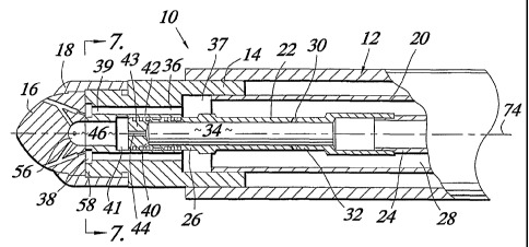
The main body portion 12 of the nozzle 10, as shown, includes concentric
tubes 20 and 22. Internal tube 22 is in the form of an elongated generally
tubular member
which may preferably have an upstream segment 24 having an upstream end that
is
adapted in a conventional manner for connection to a source of liquid fuel and
a
downstream segment 26. Fuel oil is delivered through tube 22 while steam or
some other
atomizing fluid, such as, for example, pressurized air, is delivered through
the external
tube 20 which presents an elongated, generally annular pressurized atomizing
fluid
supply conduit 28 that surrounds tube 22. The upstream end of conduit 28 is
also adapted
in a conventional manner for connection to a source of pressurized atomizing
fluid. In
connection with the foregoing, it will be appreciated by the routineers in the
fuel nozzle
art that steam may be the preferred atomizing fluid whenever the fuel is a
heavy fuel oil.
On the other hand, when the fuel of choice is a lighter, more volatile oil,
pressurized air
may be the preferred atomizing fluid
As is well known to those of ordinary skill in the art field which is
applicable to the invention, the fuel oil may pass through a small orifice
(not shown)
before it is introduced into the downstream segment 26. Such a small orifice
is used to
control the flow of the fuel oil. In addition, the fuel oil may be partially
atomized as a
result of having passed through such an orifice.
CA 02365615 2001-09-05
WO 01/55640 PCT/USO1/00618
One or more orifices 30 may be provided in a wall 32 of the downstream
segment 26 of tube 22. These orifices 30 intercommunicate conduit 28 and a
chamber
34 provided inside of segment 26 and thereby allow a portion of the steam or
other
atomizing fluid flowing in conduit 28 to be diverted into a chamber 34 where
it is
admixed with and acts to atomize fuel oil. To facilitate such flow, the
atomizing fluid
should desirably have a pressure which is greater, preferably 10 to 20 psi
greater, than the
pressure of the oil in segment 26. The steam or other atomizing fluid flowing
through
the orifices 30 is intermixed with the fuel oil in chamber 34 and atomizes or
further
atomizes the fuel oil. Thus, the chamber 34 may be referred to as a pre-
atomizer
chamber. The function of the pre-atomizer chamber 34 is thus to facilitate the
pre-
atomization of the fuel oil and the pre-mixing of the oil and the atomizer
fluid.
The intermediate portion 14 of the atomizer 10 may include a plurality of
bores or tubes 36 which are in fluid communication with conduit 28 via an
annular
chamber 37 as shown. Although the atomizer of the invention is illustrated as
having
four holes (See Fig. 7), it will be recognized by those skilled in the art
that the actual
number of bores 36 may vary depending upon the amount of steam which is
desired for
atomizing fuel in atomization tip 16. In some case, in accordance with the
concepts and
principles of the invention, the atomizer 10 may have as many as ten or more
bores 36
in portion 14. Generally speaking, the bores 36 may preferably be spaced
evenly around
the longitudinal axis 74 of atomizerl0. Whatever the number thereof, the
downstream
ends 39 of bores 36 are arranged to open into an annular groove 38 provided in
portion
14.
The downstream end 40 of segment 26 is received in an opening 41 in
portion 14 and the joint between end 40 and opening 41 may preferably be
sealed by a
series of labyrinth grooves 42 as shown. In this regard it is to be noted also
that chamber
34 in segment 26 is closed off at end 40 by an annular portion 43 presenting a
hole 44 of
reduced diameter. Hole 44 intercommunicates chamber 34 in segment 26 and a
chamber
46 in portion 14 via the portion of opening 41 which is not filled by end 40.
Atomization tip 16 of the atomizer nozzle 10 is best shown in Figs. 2, 3
and 4 of the drawings. Tip 16 preferably includes an internal chamber 56 and a
mixing
port arrangement which preferably is in the form of a plurality of generally y-
shaped port
CA 02365615 2001-09-05
WO 01/55640 PCT/USO1/00618
_g_
arrays 48 which extend through tip 1G. As shown, tip 16 has four of these y-
shaped port
arrays 48, however, the actual number may vary depending upon the desired
operational
characteristics of the burner in which the atomizer nozzle 10 is used. It is
to be noted in
regard to the tip that in accordance with the broadest aspects of the
invention, the exact
configuration of the mixing ports is not critical so long as the tip operates
to bring the
atomizing fluid into intimate contact with the liquid fuel in a manner such
that the liquid
fuel is atomized.
Even though the tip 1 G may include a plurality of y-shaped port arrays 48,
these port arrays are of essentially the same configuration. Accordingly, for
purposes of
the present description only one port array 48 will be described with
reference to Figs.
2, 3 and 4. Each port array 48 preferably may include a fuel oil port 50 that
is arranged
in fluid communication with the chamber 34 via hole 44, chamber 46 and chamber
56,
and an atomizing fluid port 51 which includes an entrance portion 52 that is
arranged in
fluid communication with the conduit 28 via groove 38, tubes 36, and chamber
37, and
an outlet port portion 54 that is in fluid communication with both the port 50
and the
entrance portion 52. As can be seen viewing Fig. 4, the outlet port portion 54
and the
atomizing fluid entrance port portion 52 are in substantial alignment. As can
also be seen
viewing Fig. 1, internal chamber 56 is aligned with and is arranged in fluid
communication with chamber 4G in intermediate portion 14. Fuel oil port 50
opens into
and is in fluid communication with chamber 5G as shown. Entrance portion 52 is
of a
reduced diameter relative to portion 54 and opens into and is in fluid
communication with
annular groove 38.
Tip 1G preferably has a flat surface 80 which sealingly engages a pair of
flat annular surfaces 82 and 84 (see Fig. 7) of segment 58 of portion 14 as
shown. The
tip shroud 18, which may be attached to a reduced diameter segment 58 of
intermediate
portion 14 by threads or welding or the lilce, simply holds the tip 1 G and
the intermediate
portion 14 together as shown in Fig. 1, with surface 80 in sealing contact
with surfaces
82 and 84.
In operation, using superheated steam as an atomization fluid, and with
reference to the embodiment illustrated in the drawings, steam is injected
into chamber
34 via apertures 30 and mixes with and at least partially atomizes oil in
chamber 34. A
CA 02365615 2001-09-05
WO 01/55640 PCT/USO1/00618
-9-
mixture of fuel oil and steam then flows out of pre-atomizer chamber 34,
through hole
44, through chambers 46 and 56, and into the ports 50. This pre-atomized
mixture of fuel
oil and steam is thus divided into as many streams as there are port arrays 48
in the
atomizer tip 16.
The stream passing through each port 50 shoots into the corresponding
outlet port portion 54 at an angle, as is best shown in Figs. 4 and 8. It has
been
determined that the stream passing through port 50, which comprises a pre-
atomized
mixture of fuel oil and steam, and which shoots into outlet port portion 54 at
an angle,
thereby forms an annular conical sheet of the fuel oil/steam mixture along the
internal
wall of outlet port portion 54. This conical sheet is shown schematically in
Fig. 8, where
it is identified by the reference numeral 70.
Steam from conduit 28 passes through bores 36 and collects in annular
groove 38. Since entrance portions 52 of ports 51 are in fluid communication
with
groove 38, steam is also divided into as many streams as there are port arrays
48 in the
atomizer tip 16. The steam from groove 38 travels through portion 52 and joins
the fuel-
steam mixture shooting into port portion 54 from the port 50. The steam from
port
portion 52, which preferably is traveling at sonic velocity, pierces the
conical sheet as
shown schematically by the arrows 72 in Fig. 8 and becomes intimately
intermixed with
the steam-fuel oil mixture from port 50, whereby further atomization occurs in
outlet
portion 54. Thus, outlet portion 54 serves as a final mixing chamber for the
final oil-
steam mixture. In this latter regard, it is to noted that in the portion 54,
the fuel is pushed
out against the inner wall of the portion 54 where it is in the form of a
hollow annular
flow. The atomizing fluid is in the hollow center whereby the contact area
between the
atomizing fluid and the fuel is maximized.
In accordance with the preferred aspects of the invention, the amount of
the atomizing fluid which is injected into the chamber 34 through apertures 30
way vary
from about 15% to about 75% of the total flow of the atomizing fluid. The
remainder,
of course will be injected into port 51 through port portion 52. It is also to
be recognized
in this regard, however, that if the atomizing fluid is heated, such as it
would be if it were
steam, a certain improvement in efficiency will be obtained even if no
apertures are
provided and 100% of the atomizing fluid is channeled through port 51. In such
a case,
CA 02365615 2001-09-05
WO 01/55640 PCT/USO1/00618
-10-
the tubes 20, 22 act as a heat exchanger to cause the fuel in tube 22 to
become heated.
The result is that the viscosity of the fuel is decreased and the atomizing
thereof which
takes place in the nozzle tip 16 is thus facilitated.
It is to be particularly noted, that in accordance with the invention, the
steam travels in a straight line after it enters portion 52, whereby high
steam velocity
(preferably sonic) is facilitated until such time as the steam encounters the
annular
conical sheet 70 of fuel oil mixed with steam exiting from port 50. Such high
velocity
steam exerts a very high shear force against the annular conical sheet 70
formed by the
steam-fuel oil mixture exiting from port 50 and shooting into portion 54 at an
angle. This
interaction facilitates the atomization of the fuel oil into a fine mist.
When the fuel oil is pre-mixed with a portion of the atomizing fluid in
chamber 34, as described above, the oil port 50 of the y-shaped port array 48
is preferably
enlarged so as to carry the greater volume of fluid, whereby clogging is
reduced and
minimized. Moreover, and particularly when the atomizing fluid is heated, such
as would
be the case when steam is used as the atomizing fluid, the viscosity of the
fuel oil is
reduced so as to increase the overall efficiency of the atomization process.
In accordance
with the preferred aspects of the invention, the ratio of the cross-sectional
flow area of
each port 50 to the cross-sectional flow area of each corresponding port
portion 52 may
preferably be within the range of from about 1.2 to about 3, depending upon
the split of
the atomizing medium between premixing and atomizing. It is to be noted also
that Port
54 is necessarily larger in cross-sectional flow area then either port 50 or
52 because it
must be large enough to carry the both the fuel and the total amount of the
atomizing
fluid. Preferably, the flow area of each port 54 may range from about 1 to
about 1.7 times
the total of the flow areas of the corresponding port 50 and port portion 52.
But it is to
be noted that the port sizes may vary depending upon desired results and upon
the ratio
of total atomizing fluid to fuel and the relative amount of atomizing fluid
that is injected
into chamber 34 via apertures 30. As is well known to the mutineers in the
burner art,
the main design parameters are flame length and NOX emissions. A long flame
will
reduce the NOX emissions while a short flame does the opposite. Accordingly,
the
designer is called upon to decide what trade-offs are desirable for any given
application.
CA 02365615 2001-09-05
WO 01/55640 PCT/USO1/00618
-11-
Port 51 is preferably positioned at an angle relative to a longitudinal axis
74 of the fuel oil atomizer 10. This angle may preferably range from about
2° to about
30°, depending on what is needed for optimizing the overall
application. As will be
appreciated by those slcilled in the burner art, the desirable spray angle may
change from
application to application. The angle of port 50 relative to port 51 may also
vary,
depending upon the angle of port 51 relative to longitudinal axis 74 and the
relative size
of the nozzle tip 16. Preferably this angle between ports 50 and 51 may range
from about
° to about 70 ° .
The fuel oil atomizer nozzle 10 of the present invention provides a number
10 of benefits which were not previously lcnown in the prior art. These
benefits include, but
are not necessarily limited to, (1) the concentric tubes 20, 22 for oil and
atomizing fluid
facilitate the injection of atomizing fluid into the fuel via apertures such
as the apertures
30 as well as the heating of the fuel, (2) the configuration of the y-shaped
port arrays 48
in the nozzle tip 16 provides for the straight line travel of the steam and
the angled
15 entrance of the fuel oil into the final mixing chamber, (3) the monolithic
design of the
nozzle tip 16 provides improved efficiency and economics, (4) atomization of
the fuel
prior to discharge of the same into the burner is improved as a result of the
double
atomization provided first in the pre-atomizer and secondly in the y-shaped
port array,
(5) the mixing of oil with steam in the pre-atomizer facilitates the use of
larger oil ports
in the y-shaped port array whereby clogging is minimized, and since clogging
is often
encountered in low oil flow rate nozzles, the invention therefore covers a
wider range of
boiler capacities, (6) combustion turndown ratios of oil sprays are improved
for the same
reasons discussed above, (7) the steam surrounding the oil passageway in the
concentric
tubes helps to maintain a reduced viscosity in the oil whereby energy is
saved, (8) mixing
oil with steam in the pre-atomizer results in reduced oil viscosity and
enhances
atomization efficiency and effect, and (9) the straight line steam passage and
the overall
configuration provided in the y-shaped port array preserve steam momentum and
shape
the oil so that higher shearing forces and larger shearing contact surfaces
are experienced
when the steam and the fuel oil collide in the final mixing chamber 54,
whereby
atomization is optimized and steam consumption is reduced.
CA 02365615 2001-09-05
WO 01/55640 PCT/USO1/00618
-12-
Through the use of the concentric tubes 20, 22, heat is readily transferred
from the steam in the outer tube 22 to the fuel oil in the center tube 20, to
thereby heat
up the fuel oil and decrease its viscosity. Atomization is facilitated when
the viscosity
of the oil is lower. In addition, with the concentric tubes 20, 22, it is a
simple matter to
provide one or more passageways 30 for introduction of steam into the fuel oil
in
chamber 34 for pre-atomization purposes.
The configuration of the y-shaped port arrays 48 provides for straight line
travel of the steam and angular travel of the fuel oil and insures the
maximization of the
shear forces when the steam encounters the conical sheet 70 of oil shooting
into the
mixing chamber provided in port portion 54. The straight atomizing fluid jets
72 contain
higher momentum than a jet of atomizing fluid that is forced to turn. On the
other hand,
the angular injection of the fuel oil-steam mixture from port 50 creates a
conical sheet 70.
The conical sheet 70 not only reduces the characteristic thickness of the bulb
liquid, but
also increases the contact surface which is encountered by the high momentum
atomizing
fluid. Both aspects, i.e., straight line atomizing fluid flow and conical
mixture sheet,
greatly enhance the atomization process. Thus, atomizing fluid energy is
conserved
thereby increasing the efficiency of the atomization process.