Note: Descriptions are shown in the official language in which they were submitted.
CA 02365871 2001-09-12
WO 00/55543 PCT/US00/07022
IMPROVED FCC FEND INJECTOR FAN TIP DESIGN
This application is a continuation in part of U.S. Patent Application Serial
Number 09/271.813. tiled March 18. 1999.
BACKGROUND OF THE DISCLOSURE
FIELD OF THE INVENTION
The invention relates to tluidized catalytic cracking ("FCC") processes
using a high fluid throughput and low pressure drop, liquid atomizing process
and apparatus. The process comprises forming a fluid mixture of a hot feed oil
and a dispersion gas. such as steam, atomizing the mixture to form droplets.
and
then distributing the droplets into the FCC process. The apparatus comprises a
nozzle having an improved spray distributor end section.
BACKGROUND OF THE INVENTION
Fluid atomization is well known and used in a wide variety of
applications and processes. These include. for example. aerosol sprays. the
application of pesticides and coatings, spray drying, humiditication. mixing,
air
conditioning, and chemical and petroleum refinery processes. For most
applications. a fluid under pressure, with or without the presence of an
atomizing
agent, is forced through an atomization nozzle having a relatively small
orifice.
Atomization occurs at the downstream side of the orifice. with the degree of
atomization determined by the orifice size. the pressure drop across the
orifice.
fluid density, viscosity. and surface tension. etc., as is known. Atomization
is
increased and the droplet size is decreased. with decreasing orifice size and
increasing pressure drop. Increasing the degree of atomization of relatively
viscous fluids at high flow rates. such as the heavy petroleum oil feeds used
in
WO 00/55543 CA 02365871 2001-09-12
PCT/US00/07022
an FCC process, or fluid cat cracking as it is also called. is particularly
challeneine. FCC is an established and widely used process in the petroleum
refining industry, primarily for converting high boiling petroleum oils to
more
valuable lower boiling products. including gasoline and middle distillates
such
as kerosene. jet and diesel fuel. and heating oil.
In an FCC process. a preheated feed. often mixed with an atomization
promoting fluid, such as steam, is atomized and brought into contact with a
particulate. hot cracking catalyst flowing up through a riser which comprises
the
catalytic cracking reaction zone. Smaller oil feed droplet sizes in the
reaction
zone result in more feed conversion to valuable products, particularly with
the
incorporation of heavy teed material. such as a resid, in the FCC feed. Oil
that
doesn't make contact with the uprising catalyst particles, thermally cracks
primarily to light gases. such as methane. and coke. As a consequence, efforts
continue to try to find economically viable means to decrease the droplet size
of
the atomized oil. and preferably without either (i) an unacceptably high
pressure
drop through the-atomizer or nozzle or (ii) increasing the amount of steam or
other atomization promoting agent. Examples of such efforts are disclosed in.
for example, US ,?89.976 and US ~,173.17~ which produce an average feed
droplet size in the range ot~about 400-1000 microns. There is still a need for
finer atomization of the heavy oil feed for the FCC process and of other
fluids
for other processes as well. It would be particularly beneficial if the
droplet size
of the atomized liquid could be reduced to less than 300 microns.
SUMMARY OF THE INVENTION
The invention relates to a process and apparatus for atomizing a liquid.
The process and apparatus are useful for atomizing and injecting hot teed oil
into
WO 00/55543 CA 02365871 2001-09-12 pCT/jJS00/07022
a reaction zone of a fluid cat cracker, to achieve a relatively small drop
size. and
uniform drop size distribution of the atomized oil drops or droplets.
More particularly. the apparatus of the invention relates to a spray
distributing means. such as an expanding fan-shaped spray distributor, the
interior of which comprises a tan-shaped cavity open at its upstream and
downstream ends. preferably adjacent the downstream side of the atomizing
orifice, for controlling the shape of the atomized spray.
In another embodiment. the invention comprises a process for atomizing a
liquid into a spray of liquid drops, and then conducting the drops through
spray
distributing means in order to form a distributed spray of droplets.
In a preferred embodiment. the apparatus of the invention briefly
comprises a body containing a cavity within, comprising an impingement mixing
zone and a shear mixing zone downstream of the impingement mixing zone.
wherein the cavity is elongated in the direction of fluid flow and extends
through
the body. Preferably the body contains a means for splitting a fluid stream
adjacent the upstream end of the body into two separate streams. with an
orifice
entrance for each stream to enter the cavity and into the impingement mixing
zone. The apparatus may also include a spray distributing means adjacent to
its
downstream end. the fluid .entrance of which is adjacent the fluid exit of the
shear mixing zone. with which it is in fluid communication. Preferably. the
spray distributor means is a spray distributor. The preferred spray
distributor is a
three dimensional member having
( I ) a front surface separated from a rear surface by a length L along a
first
axis and
(2) a continuous, internal. fan-shaped channel open at the front and rear
surface, the channel having
( a) t7at. parallel top and bottom surfaces separated by a constant
height h measured parallel to a second axis perpendicular to the first axis
and
WO 00/55543 CA 02365871 2001-09-12
PCT/US00/07022
_.
(b) curved first and second side surfaces both being in contact with
the top and bottom surfaces, wherein
( i) the first and second side surfaces have a mavmum
>eparation w 1 at the ti-ont surface and
(ii) a maximum separation w~ at the rear surface. w, being
smaller than w~, and both w, and w, being measured
parallel to a third axis simultaneously perpendicular to the
first and second axes.
In a preferred embodiment relating to a fluid cat cracking process, the
'invention comprises the steps of:
(a) separately passing two streams of a two-phase fluid comprising a
gas phase and a liquid phase comprising hot FCC feed oil, into an impingement
mixing zone under pressure, in which a portion of each stream impingement
mixes with the other. to form a single, impingement mixed fluid stream. in
which the surface area of the liquid phase is increased to be heater than that
in
both streams priar to mixing;
(b) passing the mixed stream formed in (a) into a shear mixing zone,
downstream and adjacent to the impingement mixing zone with which it is in
direct fluid communication. to further mix the mixed stream, primarily by
shear
mixing, to further increase the surface area of the liquid phase:
(c) atomizing the shear mixed stream, by passing it through an
atomizing means and into a lower pressure expansion zone in which said gas
expands and forms a spray comprising drops of the atomized liquid. and
(d) conducting the atomized spray through a spray distributor into a
riser reaction zone. in which it contacts a particulate. hot. regenerated
cracking
catalyst, at reaction conditions effective to catalytically crack the oil and
produce
lower boiling hydrocarbons, the spray distributor being a three dimensional
member having
WO 00/55543 CA 02365871 2001-09-12
PCT/US00/07022
_;_
( 1 ) a front surface separated ti-om a rear surface by a length L alone a f
first
axis and
(?) a continuous. internal, fan-shaped channel open at the front and rear
surface. the channel having
(a) flat. parallel top and bottom surfaces separated by a constant
height h measured parallel to a second axis perpendicular to the first axis
and
(b) curved first and second side surfaces both being in contact with
the top and bottom surfaces, wherein
( i) the first and second side surfaces have a maximum
separation w, at the front surface and
(ii) a maximum separation w~ at the rear surface, wi being
smaller than w~, and both w, and w~ being measured
parallel to a third axis simultaneously perpendicular to the
first and second axes.
The lower boiling hydrocarbons are recovered and typically at least a
portion are upgraded by one or more upgrading operations. such as
fractionation.
The cracking reaction produces spent catalyst particles. which contain
strippable
hydrocarbons and coke. as is known. The lower boiling hydrocarbons are
separated ti~om the spent catalyst particles in a separation zone and the
spent
catalyst particles are stripped in a stripping zone. to remove the strippable
hydrocarbons to produce stripped. coked catalyst particles. The stripped.
coked
catalv_ st particles are passed into a regeneration zone. in which they are
contacted
with an oxygen-containing gas. at conditions effective to burn off the coke
and
produce the hot. regenerated catalyst particles. which are then passed back up
into the riser reaction zone.
CA 02365871 2001-09-12
WO 00/55543 PCT/US00/07022
_p_
BRIEF DESCRIPTION OF THE DRAWINGS
Figures 1 (a) through 1 (d) schematically illustrate various views of an
atomizing nozzle of the invention. with Figures l (a) and ( (c) being
respectme
views from the upstream and downstream ends ofthe nozzle, Figure 1 (b) being
a cut-away side view and Figure 1 (d) a partial cut-away top mew.
Figures 2 (a) through 2 (d) schematically illustrate the nozzle of Figure 1
fabricated of stacked metal platelets, including an atomizing distributor as
part of
the nozzle.
Figures 3 (a) through 3 (d) schematically illustrate various views of
another embodiment of an atomizing nozzle of the invention, with Figures 3 (a)
and 3 (c) being respective views from the upstream and downstream ends of the
nozzle. Figure 3 (b) being a cut-away side view and Figure 3 (d) a partial cut-
away top view of Figure 3 (c).
Figures 4 (a) through ~ (c) schematically illustrate three different views
and a combination of the nozzle of Figure 3 and a preferred spray distributor.
Figure ~ is a cut-away schematic view of an atomizing nozzle and tip in
association with an upstream fluid conduit.
Figures 6 (a) through 6 (c) are views of an atomizing nozzle means of the
invention similar to that illustrated in Figures 3 and ~. but wherein the
shear
mixing zone includes an atomizing orifice.
Figure 7 is a schematic side view of an FCC feed injection umt
employing a nozzle of the invention.
CA 02365871 2001-09-12
WO 00/55543 PCT/US00/07022
_;_
Figure 8 is a simplified schematic of a fluid cat cracking process useful in
the process of the invention.
DETAILED DESCRIPTION
The two-phase fluid fed into the mixing nozzle may be gas-continuous or
liquid-continuous, or it may be a bubbly froth. in which it is not known with
certainty if one or both phases are continuous. This may be further understood
with reference to, for example. an open cell sponge and a closed cell sponge.
Sponges typically have a 1: I volumetric ratio of air to solid. An open cell
sponge is both gas (air) and solid continuous. while a closed cell sponge is
solid
continuous and contains discrete (dispersed) gas cells. In an open cell
sponge,
the solid can be said to be in the form of membranes and ligaments (such as
may
exist in a two-phase gas-liquid troth or foam). In a closed cell sponge, the
gas
can be envisioned as in the form of a dispersion of discrete gas globules in
the
solid. Some sponges fall in-between the two. as do some two-phase fluids
comprising a gas phase and a liquid phase. It is not possible to have a sponge
that is gas-continuous and not also solid-continuous. but it is possible to
have a
two-phase gas and liquid fluid that is gas-continuous only. Therefore. the
particular morpholoav of the fluid as it is passed into and through the mixing
nozzle of the invention. is not always known with certainty. Irrespective of
this,
for this embodiment of the invention. there must be sufficient gas present in
the
fluid entering the nozzle. for the impact and shear mixing to increase the
surface
area of the liquid phase. This is reelected in reducing (i) the thickness of
any
liquid membrane. (ii) the thickness and/or length of any liquid rivulets. and
(iii)
the size of any liquid Globules in the fluid. either before or during the
atomization. In the practice of the invention. impingement and shear mixing in
the nozzle and through orifices will only occur with a two-phase fluid
comprising a gas phase and a liquid phase. It is preferred that the fluid
comprise
CA 02365871 2001-09-12
WO 00/55543 PCT/US00/07022
_g_
mostly gas on a volumetric basis ( e.g., a volumetric gas to Liquid ratio ot~
at least
?: l ) for efficient shear mixing. ,~~ single phase fluid (e.g.. liquid)
passed through
the nozzle. will have its kinetic energy increased directly proportional to
the
pressure drop across the nozzle. With a two-phase fluid comprising a ~~as
phase
and a liquid phase. the gas velocity is increased relative to the velocity
ot~the
liquid phase, (i) in the impingement mixing zone. (ii) in the nozzle shear
mixing
zone. and (iii) when the fluid passes through an orifice of smaller cross-
section
perpendicular to the fluid flow direction than the fluid conduit means
upstream
of the orifice ( a pressure-reducing orifice). This velocity differential
between
tfte gas and liquid phases results in ligamentation of the liquid.
particularly with
a viscous liquid. such as a hot FCC teed oil. By ligamentation is meant that
the
liquid forms elongated globules or rivulets. The velocity differential is
decreased during shear mixing. Thus, passing a two-phase fluid through a
pressure-reducing orifice or impingement mixing it, produces a velocity
differential between the gas and liquid which results in ligamentation oFthe
liquid and/or dispersion of the liquid in the gas due to shearing ot~ the
liquid into
elongated ligaments and/or dispersed drops. Additional shear ot~ the liquid
occurs when the Iluid enters the orifice entrances of the nozzle and through
the
atomizing orifice. This additional shear also adds to reduction ot~ the
ultimate
droplet size of the oil droplets in the atomized spray. The atomizing zone is
at a
lower pressure than the pressure upstream of the atomizing orifice.
Consequently, the Qas in the fluid passing through the atomizing orifice
rapidly
expands, thereby dispersing the liquid rivulets and/or droplets into the
atomizing
zone. Anv rivulets break into two or more droplets during the atomization. The
atomizing orifice may be a discrete. readily discernable orifice downstream of
the shear mixing zone. or it may be in the form of a region or zone of the
smallest cross-sectional area inythe shear mixing zone. In the later case.
fluid
atomization begins in the shear mixing zone of the nozzle. In the strictest
technical sense. atomization sometimes refers to increasing the surface area
of a
liquid and this occurs when the steam or other atomizing gas is mixed with. or
CA 02365871 2001-09-12
WO 00/55543 PCT/US00/07022
_y_
injected into, the liquid to be atomized. However. in the context ot~ the
invention. atomization means that as the tluid passes through the atomizing
orifice, the liquid phase breaks up. or begins to break up, into discrete
masses in
the gas phase and this continues as the fluid continues downstream and the
liquid
is atomized into a spray of droplets dispersed in the gas phase.
Referring now to Figure l, there are shown tour different schematic views
of an embodiment of an atomizing nozzle of the invention 10. Thus, nozzle 10
is shown as a cylindrical body 12. the interior of which comprises a single.
unitary and generally longitudinal cavity 14, open at both ends and having a
longitudinal axis coincident with the longitudinal axis of the nozzle. The
upstream and downstream ends of cavity 14 are located at the respective
upstream 16 and downstream 18 ends of the nozzle, for fluid to t7ow through.
Cavity 14 is generally rectangular in cross-section normal to the longitudinal
axis and is divided into three sequential zones. all of which are in fluid
communication, with adjacent zones in direct fluid communication. Qeginning
at the upstream end and professing downstream. cavity 14 comprises a fluid
expansion zone 20. followed by an impingement mixing zone ?? and then a
shear mixing zone or throat portion 24. The upstream opening of the cavity
comprises a pair of symmetrically identical and circle segment-shaped fluid
openings 26 and 26~. separated in this embodiment by a fluid stream splitting
means 28. Means 28 in this embodiment comprises a generally rectangular
shaped plate. which bisects the circular entrance end of the nozzle. for
splitting a
stream of flowing fluid just upstream of the nozzle. into two separate and
equal
streams, which pass into and through the fluid openings 26 and 26~. Each ofthe
two parallel edges of the plate form the chordal portion of each respective
fluid
entrance. The downstream end of the cavity 14 comprises a non-circular exit
orifice 30. In this embodiment the orifice is shown to be square-shaped.
although other shapes may also be employed. A non-circular orifice is
preferred.
This exit orifice may or may not comprise at least a portion of the atomizing
CA 02365871 2001-09-12
WO 00/55543 PCT/US00/07022
_ Ip_
means. Cavity l4 is formed by two different pairs ot~opposing walls (36-38-?3)
-(36~-38~-23~) and 3~-3~~. as shown. Walls 3~ and 34~ are identical. flat,
parallel and are rectangular in shape, while 36-38-23 and 36'-38'-?3~ are
symmetrical. The same point on a wall pair is equidistant from the
longitudinal
axis for each wall. with the intersection of walls (36-38-23)-3~ and (36~-38~-
~3~)-3~' each forming a right angle. Walls 36-38-23 and 36~-38'-23~ each begin
upstream with an arcuate or circular shape perpendicular to the longitudinal
axis
of the nozzle. substantially conforming to the circular shape of the upstream
feed
conduit and the fluid entrances of the nozzle. This shape is maintained until
the
steps 38-38' at the entrance to the throat portion 24 is reached, at which
point it
changes to a flat shape which continues (23 and ?3') until it terminates in
the
square-shaped exit 30, to more effectively utilize the impingement momentum.
This produces a more uniform size distribution of the atomized oil droplets,
than
a circular or arcuate exit would. The two symmetrically identical and segment-
shaped fluid openings 26 and 26', are diametrically opposite and radially
spaced
apart. equidistant-from the longitudinal axis. The combined cross-sectional
areas
of these two segment-shaped fluid openings is smaller than that of the small
expansion zone 20. but larger than the rectangular opening of the impingement
mixing zone immediately downstream of ?0. in order to reduce the pressure drop
of the fluid entering into the mixing zones. Bv cross-sectional area is meant
the
cross-sectional area normal to the average fluid flow through the nozzle. In
this
embodiment. it is also the cross-sectional area normal to the longitudinal
axis of
the nozzle and this is typical for a nozzle of the invention. Hereinafter. all
references to cross-sectional area will refer to the area normal or
perpendicular
to the direction of fluid flow. In this embodiment and in any typical
embodiment of the invention. the fluid openings into the cavity will be
yelocity-
increasing fluid openings. because of their smaller cross-sectional area
compared
to that of the flowing fluid stream. before being split into two separate
streams.
This can be seen. for example. in Figure ~. Looking at Figure 1 (b). a two-
phase
fluid stream comprising a gas phase and a liquid phase comprising the liquid
to
CA 02365871 2001-09-12
WO 00/55543 PCT/US00/07022
be atomized. flowing ti-om upstream into and through cavity l ~ in nozzle 10,
is
forced to split into two equal streams by means 28. with each split stream
entering into the nozzle through respective opening pairs 26 and 26~. in the
upstream end 16 of the nozzle. In the embodiment shown in f=figure l (a). the
pressure drop due to the impingement onto the splitting means 28 may be too
high for some applications and. hence, a lower pressure drop means for
introducing fluid into the nozzle can be employed. Thus. two separate tluid
streams from any convenient source and comprising a two-phase mixture of a
gas phase and a liquid phase, may be fed into the nozzle, at two radiallv
spaced
apart and substantially equal size t7uid openings. In this embodiment. the two
separate feed lines feeding the fluid two separate nozzle inlets. have to be
sized
so as to achievelthe desired fluid inlet velocity. Looking at Figure 1 (b),
each
split stream is introduced into a respective top and bottom of the cavity,
through
the velocity-increasing openings 26 and 26'. As the fluid flows through each
opening into the cavity, its velocity is increased because of the smaller
cross-
sectional area of the openings compared to that of the upstream conduit. This
results in shearing forces because the lighter gas phase accelerates more
quickly
than the heavier liquid phase. After this, each fluid stream passes into the
expansion zone. which is a controlled expansion zone 20 ( I 10 in Figure 3(b)
and
Figure 3 (d)). in the sense that the fluid is not permitted to freely expand,
as it is
in an atomizing zone. This slight expansion zone between the two fluid
entrances and the upstream end of the impingement mixing zone. reduces the
pressure drop from what it would otherwise be if the expansion zone was not
present. The outer peripheral portion of both flowing fluid streams impacts or
impinges directly onto the right angle steps 38-38' and is forced radially
inward
to impinge directly into each other in impingement zone 22. In this
embodiment in which steps 38-38' are both at right angles to the longitudinal
axis of the nozzle and cavity. the included angle between the impinging tluids
is
1800. Thus. the fluid impacting plane. taken as vertical in the drawing, is
normal to the longitudinal axis of the nozzle. This radial, right angle
WO 00/55543 CA 02365871 2001-09-12
PCT/US00/07022
- I? -
impingement directs the radially inward component of both streams to a poW t
on
the longitudinal axis, which produces the maximum impingement mixing
possible. As the fluid continues downstream. it enters the shearing zone whose
cross-sectional area decreases in the downstream direction. to increase the
tlow
velocity and further reduce the size ofthe liquid globules. primarily by
shearing.
While there is no abrupt change from the impingement mixing zone to the shear
mixing zone, in this embodiment. mostly shear mixing begins downstream of the
steps 38-38'. One pair of opposing walls 23 and 23' defining the shear mixing
zone, are sloped and converge inward in the downstream flow direction. to the
square exit orifice 30. The gradual decrease in the cross-sectional area ofthe
shear mixing zone from this downstream wall convergence results in an increase
in fluid flow velocity. with the maximum velocity achieved at the downstream
nozzle exit orifice 30.
Nozzle 10 can be fabricated in a number of different ways. at the
discretion of the practitioner. Thus a lost wax or investment casting process
could be employed. as well as forging and other casting processes. The nozzle
may be fabricated of a ceramic, metal or combination thereof. Fabrication of a
nozzle using a plurality of stacked. relatively thin metal plates or
platelets. in
order to form an article having fluid passage means therein. is known and
disclosed as useful for rocket motors and plasma torches in. for example. US
Patents 3,881.701 and ~.4».~Ol. This fabrication technique is also useful in
fabricating nozzles of the invention. including the embodiments Generally
disclosed and shown in Figures 1-fi, and nozzles of the invention have been
fabricated using this technique. However. the invention is not intended to be
limited to the use ofthis technique for nozzle fabrication. Figure 2 (a?
schematically illustrates a cross-sectional side view of nozzle 10 of Figure
1.
fabricated of a plurality of stacked metal platelets. ~0-62. The individual
metal
platelets are prepared having the required cavities and any other passages
therein. as holes. slots or orifices extending through the platelet. They are
then
WO 00/55543 CA 02365871 2001-09-12
PCT/US00/07022
- 13-
stacked together. bolted andior diffusion bonded together. to form the final
nozzle. Thus. in F figure ~ ( a). starting from the upstream end of the
nozzle.
platelet ~0 comprises a disk having the two circle segment-shaped openings in
it
defined by the stream splitting plate 28, as illustrated in Figure l (a).
I~i'~ure
(d) schematically illustrates disk ~6, which includes the shoulders 38 and
38~. In
Figure 2 (d). disk ~6 is a solid metal disk having a generally rectangular
cavity
1 ~ in its center portion. This illustrates the relative size and shape of the
cavity
14, adjacent the impingement mixing shoulders. The gradual decrease in the
distance between opposite sides of the converging walls (the vertical size of
the
opening in each platelet). starting with 57 and proceeding to 62. approximates
the opposing, flat angled throat wall sections 23 and 23', illustrated in
Figure 1
(b). While each of the radiallv inward steps of each successive disk ~7-62 is
not
large enough to impart as much radially inward momentum to the t7owing fluid.
as in the case of disk ~6. they do continue to impart a radially inward.
impingement mixing component to the tZowing fluid. Figure 2 (a) also includes
an atomizing spray distributor 64 (also referred to herein as a'tip" or "tan
tip") at
the downstream end of the nozzle. for producing a generally flat and tan-
shaped
spray of the atomized liquid. Other views of tip 64 are shown in Figures 2 (b)
and 2 (c). This unit is welded. bolted. brazed or otherwise attached to the
nozzle, thereby forming a part of the nozzle. In this embodiment. distributor
64
includes a flange 63 for attachment to a nozzle. The flange has an orifice 70
in
its center, normal to the fluid flow direction adjacent to, and the same size
and
shape as the nozzle exit (30 in Figure 1). Orifice 70 opens up downstream into
a
generally flat and divergent fan-shaped channel forming a spray distribution
tip,
defined by opposing wall pairs 66-66' and 74-74". which define a fan-shaped
atomizing zone 68. The channel is open at its front surface (i.e. the upstream
end of the channel) and at its rear surface (i.e. the downstream end ofthe
channel). Zone 68 is seen slightly converging in the vertical direction
proceeding downstream. as shown in Figure 2 (a). to control the rate of shear
mixing while the flow is diverging in the horizontal direction. as shown in
WO 00/55543 CA 02365871 2001-09-12 pCT~S00/07022
Figure 2 (c). The tip ends downstream in orifice 7?. which is oriented normal
to
the outward flow spray direction and has its longest dimension generally
perpendicular to the impingement fluid flow direction imparted by 38-38~. The
fluid exiting the orifice 30 of the nozzle. enters into the controlled
expansion
zone 68. through orifice 70. This further shears the fluid. as mentioned
above.
thereby further reducing the drop size of the liquid dispersed in the fluid.
Expansion zone 68 is at a lower pressure than that upstream of orifices 30 and
70. with the result that the gas phase rapidly expands and atomizes the liquid
to
produce a spray of the atomized liquid droplets. This further shears the
liquid
droplets and the fan shape of the atomizing tip produces a fan-shaped spray of
the liquid droplets, which continue through zone 68 and into the lower
pressure
downstream location shown in Figure 7.
Figure 3, schematically illustrates another embodiment of an atomizing
nozzle 100 of the invention. In this embodiment, as in the other embodiments
of
an impingement and shear mixing nozzle of the invention shown in the Figures.
each split stream enters the interior cavity of the nozzle substantially
parallel to
the overall fluid flow direction, which is parallel to the longitudinal axis
of the
cavity and. in these embodiments. also the nozzle. These streams are equal.
symmetrical and enter the cavity at a respective top and bottom. being
diametrically separate and opposed. as shown. In the impingement mixing
portion of the cavity. a radially inward flow component. normal to the
longitudinal axis, creates the impingement mixing. The single stream formed in
the impingement mixing zone or portion, flows generally parallel to the
longitudinal axis in the shear mixing zone and out of the nozzle. A view of
the
nozzle from the upstream end and a side view in partial cut-away fashion are
respectively shown in Figures 3 (a) and 3 (b). Thus, nozzle 100 is shown as a
cvlindricalrbodv 102 containing a single. longitudinal cavity 10~ within.
being
symmetrical about its longitudinal axis. which is coincident with the
longitudinal
axis of the nozzle. Cavity 10~ is open at both ends for fluid to flow through.
CA 02365871 2001-09-12
WO 00/55543 PCT/QJS00/07022
-I~-
with its tluid entrance and exit ends. extending through the tluid upstream
106
and exit downstream 108 ends of the nozzle, as shown. Cavity 1 (>4 comprises a
sequence of three zones, all in fluid communication with each other. starting
at
the upstream end of the cavity they are. ( i) a tluid expansion zone I 1 U. (
ii) a
tluid impingement mixing zone 1 12 and a fluid shear mixing zone 1 1-~, with
the
impingement and shear mixing zones having substantially rectangular cross-
sections. As is the case for the nozzle of Figure 1. the fluid passed from
upstream into nozzle 100 is a two-phase fluid comprising a gas phase and a
liquid phase comprising the liquid desired to be atomized. The upstream end
106 of the nozzle contains a pair of symmetrically identical fluid entrance
orifices 1 I6 and 116', diametrically opposed and radially spaced apart,
equidistant from the center and in the shape of a segment of a circle. As is
the
case for the nozzle of Figure l, in this embodiment the two fluid entrances
are
also radially equidistant from the center and separated by a generally
rectangular
stream-splitting plate t 18. which bisects the circular entrance end of the
nozzle.
and with each of the two parallel edges 1 I9 and 1 I9' of the plate. forming
the
chordal portion of each respective fluid entrance. Thus, a fluid t7owing ti-om
upstream into the nozzle is split into two identical streams. each of which
passes
into and through a respective t7uid entrance 1 16 and I 16' and into the
interior of
the nozzle. In this embodiment, and as is shown in Figure 4. the cross-
sectional
area of each fluid entrance is less than half that of the upstream fluid
conduit.
This means that the velocity of each of the two streams entering a respective
entrance is greater than that immediately upstream. This produces a shearing
action on the two-phase t7uid, thereby increasing the surface area of the
liquid
phase. Looking at Figures 3 (b). Figure ~ (a) and Figure ~. a t7uid stream
flowing into and through nozzle 100 is forced to split into two equal streams
by
meansyl 18. each of which enters into the nozzle through respective equal size
orifices I 16 and 1 16'. While splitting a single fluid stream into two
separate
streams in this fashion is convenient. the invention is not limited to this
embodiment. In the embodiment shown in Figure 3, the pressure drop due to the
WO 00/55543 CA 02365871 2001-09-12
PCT/US00/07022
- 16-
impingement onto the splitting means may be too high for some applications. A
lower pressure drop means can be employed or two separate streams from any
convenient source may be ted into the upstream end of the chamber 104. and
preferably through shear-inducing orifices. Also, as is the case for the
nozzle of
Figure l.-the cross-sectional area relationships ofthe fluid entrances, the
expansion zone 1 10 and the upstream opening of the impingement mixin~~ zone
also apply here. As each fluid stream enters into the open-ended. unitary and
singular cavity 104 longitudinally extending through the nozzle. it
immediately
enters into the expansion zone 110 just upstream of the impingement mixing
zone 112. so that it can be turned radially inward without an excessive
pressure
drop. This is not an uncontrolled expansion, but it minimizes coalescence of
the
smaller liquid drops formed by passing the fluid through the entrances. As
each
stream continues downstream. the circumferentially outer portion contacts a
means which imparts a radially inward flow component to it, thereby forcing a
portion of each stream to flow radially inward, where it impinges and impacts
the radiallv inward flow from the other stream. head on. This causes violent
and
chaotic mixing, which converts kinetic energy into increased liquid phase
surface tension energy, as reflected in an increase in the surface area of the
liquid phase. This surface area increase ultimately manifests itself as
smaller
liquid droplets in the final atomized liquid spray. Two arcuate.
circumferential
or peripheral shoulders. 1?'? and 1??'. extending radially inward ti-om walls
125
and 1?~'. impart the radially inward flow component to each fluid stream as it
impinges upon each shoulder. thereby forcing a portion of each stream against
a
portion of the opposite stream being directed towards it. Thus. the radially
inward flows are directed against each other in a head-on fashion. thereby
producing violent and turbulent mixing to further increase the surface tension
energy of the liquid phase of the fluid. This inward flow component is normal
to
the longitudinal axis of the nozzle. The plane of both of the shoulders 1??
and
1'_'~' is normal to the longitudinal nozzle axis and parallel to the flat (
106 and
108) ends of the nozzle and. therefore. concomitantly parallel to the tluid
exit
CA 02365871 2001-09-12
WO 00/55543 PCT/US00/07022
- 17-
orifice 128 of the nozzle and mixing cavity. Although slight divergence from
normal can be tolerated. it is preferred that the plane ot~ the shoulder
surface he
within 90~ ~ ~" of the longitudinal axis ot~the nozzle. This is also the case
for
the nozzle of Figure 1. ft is preferred in the practice of the invention that
the
t7uid exit orifice ot~the nozzle not be circular for the reasons given
previously.
Thus, the exit orifice l28 will have one dimension longer than the other, and
it is
preferred that the longer dimension of the generally rectangular-shaped
impingement mixing zone be normal or perpendicular to the longest dimension
ofthe fluid exit orifice. The turbulent fluid passes from the impingement
mixing
zone into and through the shear mixing zone 114, which may also be referred to
as a throat. This zone is also Yormed by two pairs of opposing and generally
parallel walls 130-130' and 126-126', which intersect at a 90o angle. to form
the
generally rectangular-shaped cross-section. As is shown in Figures 3 (b) and 3
(d), the shear mixing zone in this embodiment is defined by these two pairs
ot~
radially opposite and opposing walls, one pair of which. 126 and 126'.
converge
inward in the downstream flow direction and the other pair of which. 130 and
130'. diverge outward in the downstream flow direction. The net effect is
either
a generally overall constant cross-section of the shear mixing zone normal to
the
fluid flow. or one that converses and then diverges by from about 10-~0% lamer
than the minimum cross-sectional area. For this embodiment. it will be taken
as
a ~enerallv constant cross-section. This design of diverging and conversing
walls produce a shear mixing zone having a lower fluid pressure drop through
it.
than the embodiment illustrated in Figure 1. It also reduces the possibility
of
coalescence in the shear mixing zone, as compared to that shown in Figure 1.
The orifice entrance 132 to the shear mixing zone 1 14 is defined by the
radially
inward edge of shoulders 1 ??-1 ?'?' and the intersection of walls 1 ?-I-130
and
124'-130'. The cross-sectional area of the orifice entrance to the shear
mixing
zone is smaller than that of the combined areas of 1 16 and 1 16~. This
increases
the velocity of the fluid as it flows into the shear mixing zone. In this
embodiment. the divergence and convergence of the two pairs of opposing walls
CA 02365871 2001-09-12
WO 00/55543 PCT/US00/07022
18-
of the shear mixing zone shape the t7uid flow into a generally rectangular
shape
at the exit orifice 128, as is shown in Figure 3 (c). This is done to
accommodate
the tlow from the nozzle ( 00. smoothly into the atomizing spray distribution
tip
1~0. as shown in Figure ~1.
Thus. turning to Figures ~ (a), ~ (b) and 4 (c). it is seen that these Figures
are similar to Figures 3 (b). 3 (c) and 3 (d), respectively, with the
exception of
the atomizing spray distribution tip 150 adjacent and attached to the
downstream
orifice exit of the nozzle 102 in Figure ~. This was omitted from Figure 3,
for
clarity and ease in understanding the invention. Thus, atomizing spray
distribution tip 1 ~0 comprises a generally tan-shaped body I ~ 2 containing a
fan-
shaped channel or cavity 1 ~4 within, defined by opposing and outwardly
diverging walls (side walls] 15~ and 15~'. which serves to control the
expansion
of the atomizing fluid, into a fan-shaped spray. As discussed, the walls may
be
curved in a direction approximately perpendicular to the divergence.
Preferably
the side walls' curvature is such that the volume of the channel is increases,
as
shown in figure ~(b?. The fluid entrance 158 of the tip is an opening in the
ti-ont
(i.e. upstream) end of the channel and corresponds in shape to the fluid exit
128
of the nozzle to which it is attached. The exit 160 of the tip is an opening
in the
rear ( i.e. downstream ) end of the channel which is larger in order to permit
the
atomized spray of liquid drops to continue expanding into a fan-shaped spray.
The pressure in 1 ~~ is lower than that in the nozzle cavity. Accordingly. the
side
walls are separated by a width w, -at the channel's front surface and a width
w, at
the channel's rear surface. In cases where curved side walls are employed. w,
and w~ are measured where the side wall separation is the widest. which will
usually be the center of the channel measured along a line separating the
channel's top surface from the bottom surface. Preferably, wl is at least
about
1.~(L), where L is the length of the channel measured from the front to the
rear
surface in a direction approximately parallel to fluid flow. Preferably. w, is
at
least about 1.~(w,1.
CA 02365871 2001-09-12
WO 00/55543 PCT/LJS00/07022
_ ~ c~ _
It should be noted that while flat. parallel top and bottom channel surfaces
are generally preferred. they may be curved. Further, they may diverge in a
fan-
shaped manner with the separation increasing from upstream to downstream. It
should also be noted that while the side walls will generally have the same
curvature, the curvatures may be independently selected. Preferably. the
curvature is circular ( i.e. in one view the side is an arc of a circle. as
shown in
figure 4(b), and the radius of curvature of either side wall may be
independently
selected. The preferred radius of curvature is about h/2 where h is the height
of
the channel in the direction approximately parallel to the side walls and
approximately perpendicular to fluid flow. While not required. the center of
each side wall's radius of curvature is generally located near a line parallel
to the
top and bottom surfaces, the line being preferably located at the midpoint
between the upper and lower surfaces and approximately perpendicular to the
direction of fluid flow in the channel.
The mixed tluid exiting the nozzle into the lower pressure atomizing
cavity 1 ~4. atomizes into a fan-shaped spray of liquid droplets. which
continue
out of the exit end 1 s6 of the tip and into a riser reaction zone of an FCC
unit.
such as that shown in Figure 7. Figure ~ schematically illustrates a cut-away
view of an atomizing nozzle and tip. in association with an upstream fluid
conduit. Fluid conduit 16~ provides the flow path for the fluid trom an
upstream
source to be split into two separate and equal fluid streams. which pass into
the
respective nozzle entrances 116 and 116'.
Figure 6 is another embodiment of an atomizing nozzle of the invention
in which the shear mixing zone is actually a compound zone which includes both
shear mixing and atomization. by virtue of an atomizing zone in the shear
mixing zone. Atomizing nozzle 170 shown in Figure 6 is identical to nozzle 100
shown in Figures 3 and ~. except for the shape of the fluid inlet orifices and
WO 00/55543 CA 02365871 2001-09-12
PCT/IJS00/07022
?0 -
shear mixing zone. Thus. nozzle 170 includes a cylindrical body 172 containing
a unitary cavity 174 within. for impact and shear mixing the two-phase tluid
tlowing through the nozzle. As shown in Figure 6 (a), tluid inlets 1 17 and 1
17'
need not be complete segments. itthe upstream teed conduit (e.'~.. 164 in
Figure
~) is suttlcientlv large to allow an acceptable nozzle entry pressure drop.
The
shear mixing zone I 1 ~, has a complex shape in which the cross-sectional area
of
the zone, starting upstream at 121 and 121', at first decreases and then
increases.
prior to the downstream fluid exit 128. Two partial cross-section views of the
nozzle taken at 6 (b) - 6 (b) and 6 (c) - 6 (c) are shown in Figure 6 (b) and
F-figure 6 (c), to illustrate the somewhat complex nature of the shear mixing
zone.
In this embodiment, the atomizing zone comprises the region or zone of
smallest
cross-sectional area within the shear mixing zone and occurs between the
beginning of the shear mixing zone at 121-121' and exit orifice 128. Orifice
128
is of the same size and shape as that in the nozzle illustrated in Figures 3
and 4.
The shear mixing zone in this embodiment. also includes an atomizing means in
the form of the zane of smallest cross-sectional area. In operation. as the
two-
phase fluid flows through the orifice and into a lower pressure atomizing zone
downstream, atomization is promoted by the rapid gas expansion in the lower
pressure in the atomizing zone and also by the more rapid acceleration of the
lighter. compressible gas than the higher density (and incompressible) liquid
phase. This induces shear until their velocities more nearly equalize. This
shear
further decreases the ultimate size of the oil droplets in the atomized spray.
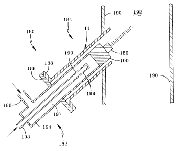
Referring now to Figure 7, an FCC feed injection unit 180 useful in the
practice of the invention comprises a hollow feed injector 182. attached to a
nozzle means 184. by means of respective flanges 186 and 188. Nozzle means
I 84 is shown as a conduit penetrating through the wall 190 of an FCC riser
and
into the riser reaction zone 192. The riser is a cylindrical, hollow. and
substantially vertically oriented conduit. in a portion of which (the riser
reaction
zone 1 the atomized oil feed contacts the uprising, hot catalyst particles and
is
WO 00/55543 CA 02365871 2001-09-12 pCT/jJS00/07022
?I -
cracked into more useful. lower boiling hydrocarbon products. (>nly a portion
ot~
the riser conduit is shown for convenience. The teed injector means 182
comprises a hollow conduit 194. into which the preheated oil teed is
introduced
via teed line 196. which forms a ~T-,junction with the wall of the upstream
portion
of the injector. The downstream portion of the injector terminates m an
impingement and shear mining nozzle 100 of the invention, having a fan-shaped
atomizing tip or distributor 1 ~0 as is illustrated in Figure 4, both of which
are
shown as boxes for convenience. The fan-shaped distributor 150 produces a
relatively flat, fan-shaped spray of the atomized oil into the riser reaction
zone
192. A steam sparging conduit 198, having a smaller diameter or cross-
sectional
area than the injector conduit 194, extends into and is axially aligned with
the
longitudinal axis ~of conduit 194. In this embodiment, the central,
longitudinal
axes of both conduits are coincident. This provides an annular t7ow path 197
for
the hot oil, upstream of the exit end of the injector. Steam conduit 198
terminates inside conduit 194, upstream of the nozzle 100. It should be noted
that steam may also or alternatively be mixed with the feed external to the
nozzel, as shown in figure 8. A plurality of holes or orifices 199. radially
drilled
circumferentiallv around the downstream end portion of 198. provide the means
for sparging jets of steam radially out and into the annularly surrounding.
hot oil
tlowin~ downstream towards the atomizing end of the injector. This produces a
two-phase fluid comprising globules of hot oil dispersed in steam. The amount
of steam sparged into the oil is typically between 1 and ~ wt.
°,'° of the hot oil
feed. The resulting t7uid mixture. which may typically comprise. on a volume
basis. 7~-85 % steam and 1 ~-? ~ % oil, is passed to the nozzle 100 which
splits it
into two separate steams which separately enter the nozzle. The two streams
are
impingement mixed in the nozzle to form a single stream. which continues into
and through the shear mixing zone in the nozzle. The mixing in the nozzle
substantially reduces the size of the oil drops dispersed in the steam. As the
fluid exits the orifice at downstream end of the nozzle, which is an atomizing
orifice. it passes into the lower pressure controlled expansion zone defined
by
WO 00/55543 CA 02365871 2001-09-12 pCT/jJS00/07022
the interior ofthe atomizing tip. The atomizing orifice and controlled
evpans~on
cone (shown in Figure 4) are both in fluid communication with the lower
pressure riser reaction zone 192. The atomized spray ot~ oil drops proceeds
into
the riser reaction zone 192. in which it contacts an uptlowing stream ot~ hot
catalyst particles (not shown). which catalvticallv crack the heavy oil feed
into
the desired lower boiling product fractions.
Figure 8 is a simplified schematic of a fluid cat cracking process used in
conjunction with a teed injection method and atomizing nozzle means of the
invention. Thus. an FCC unit 200 useful in the practice of the invention is
shown
comprising a catalytic cracking reactor unit 202 and a regeneration unit 204.
Unit 202 includes a feed riser 206, the interior of which comprises the
reaction
zone, the beginning of which is indicated as 208. It also includes a vapor-
catalyst disengaging zone 210 and a stripping zone 2I2 containing a plurality
of
baffles 2 I4 within, in the form of arrays of metal "sheds" which resemble the
pitched roofs of houses. A suitable stripping agent such as steam is
introduced
into the stripping zone via line 216. The stripped. spent catalyst particles
are fed
into regenerating unit 204 via transfer line 218. A preheated FCC teed is
passed
via line 220 into the base of riser 206 at feed injection point ~2-1 oi'the
tluidized
cat cracking reactor unit 202. The feed injector shown in Fi_ure 6 is located
at
224. but is not shown in this Figure. for simplicity. In practice. a plurality
of
feed injectors will be circumferentiallv located around the feed injection
zone of
the riser. The feed injectors will be of the type illustrated in Figure 7.
Steam is
injected into the feed'injection unit via line 222. As set forth below, the
teed
may comprise a mixture of a vacuum gas oil (VGO). a heavy feed component.
such as a resid fraction. and mixtures thereof. The atomized droplets of the
hot
feed are contacted with particles of hot. regenerated cracking catalyst in the
riser.
This vaporizes and catalvticallv cracks the feed into lighter. lower boiling
fractions. including fractions in the gasoline boiling range ( typically l
()()--I00oF).
as well as higher boiling jet fuel, diesel fuel. kerosene and the like. The
cracking
WO 00/55543 CA 02365871 2001-09-12
PCT/US00/07022
catalyst is a mixture of silica and alumina containing a zeolite molecular
sieve
cracking component. as is known to those skilled in the art. The catalytic
cracking reactions start when the teed contacts the hot catalyst in the riser
at teed
injection point 234 and continues until the product vapors are separated from
the
spent catalyst in the upper or disengaging section 210 of the cat cracker. The
cracking reaction deposits strippable hydrocarbonaceous material and non-
strippable carbonaceous material known as coke, to produce spent catalyst
particles which must be stripped to remove and recover the strippable
hydrocarbons and then regenerated by burning off the coke in the regenerator.
Reaction unit 202 contains cyclones (not shown) in the disengaging section
210,
which separate both the cracked hydrocarbon product vapors and the stripped
hydrocarbons (as vapors) from the spent catalyst particles. The hydrocarbon
vapors pass up through the reactor and are withdrawn via line 226. The
hydrocarbon vapors are typically fed into a distillation unit (not shown)
which
condenses the condensable portion of the vapors into liquids and fractionates
the
liquids into separate product streams. The spent catalyst particles fall down
into
stripping zone 2 I2 inyvhich they are contacted with a stripping medium. such
as
steam, which is fed into the stripping zone via line 2I6 and removes. as
vapors.
the strippable hvdrocarbonaceous material deposited on the catalyst during the
cracking reactions. These vapors are withdrawn along with the other product
vapors via line 226. The baffles ? I4 disperse the catalyst particles
uniformly
across the width of the stripping zone or stripper and minimize internal
retluxing
or backmixing of catalyst particles in the stripping zone. The spent. stripped
catalyst particles are removed from the bottom of the stripping zone via
transfer
line 218, from which thev_ are passed into fluidized bed 228 in regenerator
204.
In the Yluidized bed they are contacted with air entering the regenerator via
line
240 and some pass up into disengaging zone 242 in the regenerator. The air
oxidizes or burns off the carbon deposits to regenerate the catalyst particles
and
in so doing, heats them up to a temperature which typically ranges from about
9~0-I400oF. Regenerator 204 also contains cyclones (not shown) which
CA 02365871 2001-09-12
WO 00/55543 PCT/US00/07022
separate hot regenerated catalyst particles ti-om the gaseous combustion
products
( flue ~~as), which comprises mostly CO~, CO. H~O and N, and teed the
regenerated catalv_ st particles back down into tluidized catalyst bed 228. by
means of diplegs (not shown). as is known to those skilled in the art. The
Yluidized bed 228 is supported on a gas distributor grid. which is briefly
illustrated as dashed line 2~4. The hot, regenerated catalyst particles in the
tluidized bed overflow the weir 246 formed by the top of a funnel 248. which
is
connected at its bottom to the top of a downcomer 250. The bottom of
downcomer 250 turns into a regenerated catalyst transfer line 2~2. The
overflowing, regenerated particles flow down through the funnel, downcomer
and into the transfer line 2~2 which passes them back into the riser reaction
zone, in which they contact the hot feed entering the riser from the feed
injector.
The Clue gas is removed from the top of the regenerator via line 2~4.
While the spray distributor may be practiced in connection with the
nozzle set forth in figures 1 through 7 and described in detail above. it
should be
pointed out that the spray distributor may be used in connection with any
atomizing nozzle. particularly atomizing nozzles for use in FCC processes. In
this regard. in an alternative embodiment the spray distributor may be used in
connection with the FCC injection apparatus and method set forth in L'.S.
Patent
No. x.173, I7~. incorporated by reference herein.
Cat cracker feeds used in FCC processes typically include gas oils. which
are high boiling. non-residual oils. such as a vacuum gas oil (VGO). a
straight
run (atmospheric) gas oil, a light cat cracker oil (LCGO) and coker gas oils.
These oils have an initial boiling point typically above about 450oF
('_32~'C),
and more commonly above about 6~0°F (343°C). with end points up
to about
1 I~OoF (621°C). as well as straight run or atmospheric gas oils and
coker gas
oils. In addition. one or more heavy feeds having an end boiling point above
10~0oF (e.a.. up to 1300"F or more) may be blended in with the cat cracker
teed. Such heavy feeds include. for example. whole and reduced crudes. resids
WO 00/55543 CA 02365871 2001-09-12 pCT~S00/07022
or residua from atmospheric and vacuum distillation of crude oil. asphalts and
asphaltenes. tar oils and cycle oils from thermal cracking ol~heavv petroleum
oils. tar sand oil. shale oil. coal derived liquids, syncrudes and the like.
~hhese
may be present in the cracker teed in an amount of ti-om about 2 to ~() volume
'%
ofthe blend. and more typically from about ~ to 30 volume 'ro. These feeds
typically contain too high a content of undesirable components. such as
aromatics and compounds containing heteroatoms. particularly sulfur and
nitrogen. Consequently. these feeds are often treated or upgraded to reduce
the
amount of undesirable compounds by processes, such as hydrotreating. solvent
extraction, solid absorbents such as molecular sieves and the like, as is
known.
Typical cat cracking conditions in an FCC process include a temperature
of from about 800-1200°F (427-648°C), preferably 850-
1150°F (454-621"C)
and still more preferably 900-l 150oF (482-621~~C), a pressure between about ~-
60 psiG, preferably ~-40 psig with feed/catalyst contact times between about
0.5-
l~ seconds, preferably about 1-~ seconds. and with a catalyst to teed ratio of
about 0.~-10 and preferably 2-8. The FCC feed is preheated to a temperature of
not more than 8~0°F. preferably no Greater than 800°F and
typically within the
range of from about X00-800"F.
The invention will be further understood with reference to the following
example.
EXAMPLE
In this experiment. an atomizing injector was used similar in design to
that shown in Figure 7 and had an atomizing nozzle of the invention similar in
design to that shown in Figure 4. The operation of this injector was compared
to
that of a commercially proven slot and fan design. similar to that shown in US
patent ~,173.17~. The commercial nozzle simulated a pipe with an end cap
containing a rectangular. slotted orifice. Both nozzles included a fan-shaped
WO 00/55543 CA 02365871 2001-09-12 pCT/jJS00/07022
spray distributor and were tabricated at a scale ot~one halfthe size of a
typical
commercial nozzle. ~fhe injector was the same for both cases. with the
difference between them being in the nozzle design. Both injectors produced a
flat. t-an-shaped spray and were mounted horizontally and oriented to produce
a
flat. tan-shaped spray with the maximum width in the vertical direction. in
the
laser light beam path of a Malvern particle sizer. This instrument is well
known
and used for measuring liquid spray characteristics. Light diffraction
patterns.
each associated with a characteristic drop size range. are focused by a
Fourier
transform lens onto a mufti-element photodetecter. The light energy
distribution
is-converted. via a computer, into a corresponding liquid droplet size
distribution.
A grid of comparative experiments was conducted varying water and
nitrogen flow rates and the Sauter mean liquid drop diameter was calculated.
assuming a Rosin-Rammier distribution function. The results for the two
different nozzle designs are compared in the Table below.
! Water ! Nitrogen ' tauter mean diameter
Injector Tv_ p e microns i
mass lb/sec i scf/sec
Commercial Fan 4.~~ r3 ?8'
I
4.99 I 0.39 -~4~
'
4.47 ; 0.6? ' ~ 13
j 3.64
0.40 ! =l~ 1
j
3.~~
0.94
~I
-1.84 I 0.93 -' ~-'
The Invention
4.97 I, 0.40 '4~
4.36 i 0.63 X91
I
3 46 0.39
1.00 16?
In all cases. at comparable water and nitrogen flow rates. the nozzle of the
invention produced an atomized spray having smaller Sauter mean diameter
WO 00/55543 CA 02365871 2001-09-12 pCT~JS00/07022
7_
liquid droplets. than did the commercial design. This shows that better
atomization was achieved with the nozzle of the invention.
It is understood that various other embodiments and modifications in the
practice ofthe invention will be apparent to. and can be readily made by.
those
skilled in the art without departing from the scope and spirit of the
invention
described above. Accordingly, it is not intended that the scope of the claims
appended hereto be limited to the e~.act description set forth above, but
rather
that the claims be construed as encompassing all of the features of patentable
novelty which reside in the present invention, including all the features and
embodiments which would be treated as equivalents thereof by those skilled in
the art to which the invention pertains.