Note: Descriptions are shown in the official language in which they were submitted.
CA 02365948 2001-12-17
CREATING A MASK FOR PRODUCING A PRINTING PLATE
BACKGROUND OF THE INVENTION
1. Field of the Invention
The invention relates to the creation of a mask for producing a printing
plate.
2. Description of the Related Art
It is generally known that, in many technical areas, masks are used for
surface treatment (printed circuitboard production) or else for printing
processes (gravure printing, in which it is not printing plates which are
fitted
but the plate cylinder surfaces themselves which are prepared as printing
plates) and lithographic processes. The objective is always, by using a
material which has properties that differ from a substrate, that is to say a
carrier of a material that differs from the mask material, to produce a
specific
structure (mask) on precisely this substrate. The mask produced in this way is
then used as a starting point for further processes. For instance, it is
intended
to protect the substrate at specific points from the action of other
substances.
The typical sequence of a previous method for creating a mask is
subdivided into the following steps:
1. creation of a film with the structure information,
2. exposing a suitable photosensitive layer on a substrate through
this film by means of a suitable light source,
3. development/cleaning in order to form the structure (mask) on the
substrate.
Then, as a further step, for example etching or else the direct use of
the mask can follow, for example as a printing plate in screen printing. By
means of this mask, all the non-printing points are covered there. The
printing
ink passes through only at the open points of the mask.
As an alternative to the sequence previously described, the following
is also already known:
-1-
CA 02365948 2001-12-17
1. applying an energy-sensitive layer to the substrate,
2. direct exposure or ablation of the structure by means of a suitable
energy source, such as a laser or electron beam, which is variable in
accordance with image information,
3. development/cleaning in order to form the structure (mask) on the
substrate, if required.
This alternative is already used in the production of gravure plates.
The mask is generally transferred to the gravure cylinder, a gelatin relief
then
generally remains on the said cylinder, its thickness corresponding to the
tonal value of the diapositive or dianegative. During etching with ferric
chloride, the iron salt diffuses through the gelatin and dissolves copper. The
etching depth may be controlled largely via the different thickness of the
relief,
via the choice of appropriate etching bath concentrations and via the etching
time.
SUMMARY OF THE INVENTION
On this basis, the object of the invention is to simplify the sequence of
mask creation, in particular for producing a printing plate, and at the same
time to improve the quality of the printing plates produced by means of a
mask.
According to the invention, a thermal transfer film carrying a thermal
transfer material is provided in proximity to a surface of a printing plate
carrier.
The thermal transfer material is selectively ablated using a laser image-
setting
unit to apply structure information directly to the surface of the printing
plate
carrier, thereby forming a mask on the printing plate carrier. Image points
and
non-image points can then be formed directly on the printing plate carrier
using the mask in order to produce a printing plate.
In order to create the structure information of a mask, a thermal
transfer film is used, which is brought into contact with the substrate, that
is to
say the surface of the printing plate carrier, by means of a suitable feed
device. An energy-sensitive layer can also be applied by directly coating the
substrate (e.g. by means of dip coating, doctoring on, spraying on, rolling on
or toning with solid or liquid toner) if appropriate in conjunction with a
post-
_2_
CA 02365948 2001-12-17
drying or hardening step, and the structure information of the mask is placed
on this layer.
The creation of the structure information is preferably carried out by
means of laser radiation, and for ablation, a power density of more than 500
MW/m2 is provided, pulsed if necessary. In this case, the laser radiation is
modulated in a suitable way in accordance with the image or non-image, in
order to produce the desired mask.
For example, U.S. Patent No. 6,226,020 discloses a method and in
particular an apparatus for producing a print by using laser-induced thermal
transfer by means of a strip-like transfer film and a substrate cylinder. The
known apparatus comprises a strip transport mechanism, which cooperates
with a traversing unit coupled to the image-setting unit which emits one or
more (laser diode array) laser beams. Therefore, the transfer film can be
moved uniformly in order to move over the substrate width of a printing plate
cylinder, the laser-based thermal printing head, driven in a known way by
means of a control unit in accordance with an image to be transferred,
introducing heat into the transfer film at each image point and therefore
performing the point-by-point transfer of the coating (thermal material) of
the
transfer film, and it being possible to cover the complete substrate surface
via
the rotation of the substrate cylinder and traversing parallel to the axis of
the
substrate cylinder.
In the case of a directly applied energy-sensitive layer, the
development/cleaning of the layer can be carried out with a suitable cleaning
apparatus, possibly with the aid of cleaning liquids, that is to say cleaning
by
means of a liquid or particle jet, combined if necessary, or cleaning by means
of brushes or cleaning by means of a washing cloth. In addition, following the
formation of the mask, the layer can also be further acted on thermally, in
order to improve its chemical resistance or mechanical properties.
The method on which the proposal of the invention is therefore based
is laser-induced thermal transfer, such as is used for producing the erasable
offset printing plates, for example as disclosed in U.S. Patent No. 5,601,022.
The system arrangement comprising the components of laser and strip
station, as disclosed by U.S. Patent Nos. 5,601,022 or 6,226,020 (thermal
-3-
CA 02365948 2001-12-17
transfer off-press construction), forms the model for an apparatus for
creating
masks.
As compared with conventional methods of mask creation, laser-
induced thermal transfer offers the advantage of being very fast and precise.
By means of laser-induced thermal transfer, the process steps of coating and
image setting are combined into one process step. As a result, time and costs
can be saved.
The image-setting quality of laser-induced thermal transfer is very high
(offset quality), so that extremely fine structures can be depicted.
The thermal transfer material which is known from the prior art
previously described and which is applied to the printing plate to be produced
is suitable to be used for mask creation by means of exposure, washing out
and etching. The thermal transfer material is opaque (light-resistant), water-
resistant and in particular acid-resistant.
The thermal transfer material does not need to be applied separately.
If it is applied to thin film strips, strip cassettes tailor-made as is known
are
used. In addition, both the creation of the mask and the production of a
printing plate by means of this mask can be performed within the printing
machine.
Other objects and features of the present invention will become
apparent from the following detailed description considered in conjunction
with
the accompanying drawings. It is to be understood, however, that the
drawings are designed solely for purposes of illustration and not as a
definition of the limits of the invention, for which reference should be made
to
the appended claims. It should be further understood that the drawings are
not necessarily drawn to scale and that, unless otherwise indicated, they are
merely intended to conceptually illustrate the structures and procedures
described herein.
BRIEF DESCRIPTION OF THE DRAWINGS
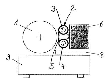
Fig. 1 shows a machine frame with an arrangement of components for
mask creation,
-4-
CA 02365948 2005-05-03
Fig. 2 shows the creation of a mask by means of laser-induced thermal
Nansfer to produce a printing plate.
Figs. 3 to 5 show details of the creation of a mask for producing a gravure
printing plate.
Figs. 6 to 8 show details of the creation of a mask for producing a
flexographic printing plate.
Figs. 9 to 11 show details of the creation of a mask for producing a screen-
printing screen, and
Figs. 12 to 14 show details of the creation of a mask for producing a screen-
printing screen by electroplating.
DETAILED DESCRIPTION OF THE PREFERRED EMBODIMENTS
Fig. 1 (and Fig. 2) shows a printing plate cylinder 1, on whose surface a
mask is to be created. A strip transport mechanism 2, comprising a supply reel
3 and
a rewind reel 4, guides a strip-like thermal transfer film 5 close to the
surface of the
printing plate cylinder 1 or brings it into contact with the surface of the
printing plate
cylinder 1. A laser image-setting unit 6 focuses one or more laser beams 7
onto the
thermal transfer film 5. The laser image-setting unit 6 and the strip guide
mechanism
2 are jointly arranged in a known way on a traversing unit 8, by means of
which they
can be moved over the width of the printing plate cylinder 1 in a machine
frame 9.
Fig. 2 shows once more how the apparatus according to Fig. 1 is used in a
gravure printing machine in order to produce an etching mask 10 (Figs. 3 and
4) by
means of laser-induced thermal transfer on the surface 11 of a gravure
printing
cylinder, by thermal transfer material 5b being transferred as image
information 5c or
structure information for the etching mask 10.
According to Figs. 3 to 5, the creation of a mask by means of laser-induced
thermal transfer can therefore be used for producing a gravure printing plate
13. In
this case, an etching method is involved, in which image information can be
etched
in a conventional way, by means of iron III chloride (Fe3Cl) onto a printing
cylinder
having a copper top layer. The process of mask creation for a gravure printing
plate
is indicated in Fig. 3, and the same reference symbols are used for the same
parts
as in Figs. 1 and 2.
-5-
CA 02365948 2001-12-17
Fig. 4 (and Fig. 3) shows the etching process in gravure printing with
the aid of an etching mask 10 produced in accordance with the invention. By
using this etching mask 10, which has to be applied to the cylinder surface
11,
differentiation with regard to image points and non-image points (image
information 5c) is carried out. The etching mask 10 is applied as a negative
mask from the transfer film 5 in the form of the thermal transfer material 5b,
so
that the intended image points 14 can be detected as free and non-covering
areas. The non-image points 15 must be covered and protected. Following
the application of the image-differentiating mask 10, the gravure printing
plate
13 can be etched, the application of acid 16 causing the cylinder surface 11
to
be attacked and depressed by the etching process at the image points 14,
that is to say the unprotected areas, and therefore gravure printing cells 18
being formed. The acid 16 attacks the surface material, generally the copper
in the case of gravure printing plates, by means of a chemical reaction, and
dissolves the material.
The material 5b, which forms the image-differentiating mask 10, must
be resistant to acid and must not be attacked by the latter. This resistance
ensures the image differentiation or the image production on the gravure
printing plate 13. The mask material 5b is also referred to as an etch resist
or
etch reserve. The adhesion of the mask material 5b to the printing plate
surface 11 must be firm and uniform. It must be ensured that the acid 16
cannot run underneath or flood underneath the mask 10. This adhesive
strength simultaneously ensures the production of an image exactly and with
sharp edges, which is of utmost significance and a necessity primarily in the
case of lines and texts. The doctor-supporting structures (webs 17) needed
for gravure printing must in this case be ensured by the laser setting of an
image by means of appropriate generation of image data during the mask
creation.
For the creation of a mask by means of laser-induced thermal transfer,
a polymer material is generally used, which is applied in thin layers to a
film
carrier. This coated thermal transfer film 5 is wound up onto a supply roll 3,
as
described at the beginning, and is unwound by an appropriate apparatus
during the process of mask creation. The means of guiding the film strip 5 is
-6-
CA 02365948 2001-12-17
oriented in such a way that the side of the film 5 coated with the mask
material 5b is assigned to the surface of the printing plate cylinder 1. In
addition to the film strip guiding means 2, a laser system 6 for producing an
image is integrated into the apparatus. This preferably diode-pumped YAG
laser system 6 transfers the image signals from a digital database by means
of high-energy laser pulses to the rear of the film 5 coated with the mask
material 5b. In the process, the distance of the film 5 from the cylinder
surface
must be very small, so that, as soon as the high-energy laser radiation 7
strikes the rear of the film, the mask material 5b can be transported from the
front side of the film to the surface of the cylinder 1 with sufficient
exactness
and completeness.
The cylinder rotational speed and the speed of the film strip advance
are determined by the efficiency of the laser system. The lateral advance in
the direction parallel to the axis of the cylinder is predefined by the number
of
laser diode arrays. The principle of rotational image setting with a laterally
traversing advance ensures that it is possible to create a seamless mask on
the gravure printing roll to be processed.
Laser-induced mask creation is an autotypical image-forming method,
that is to say the image information is applied to a variable area with
simultaneous constancy of layer thickness. For successful processing in the
etching process, the mask must have been transferred by the negative
process. The image points 14, that is to say the gravure printing cells 18,
which are intended to be depressed on the gravure printing plate after
etching, must be recognizably exposed after the masking operation, that is to
say these areas must not be covered by the etching mask 10. The non-image
points 15 must be recognizably covered by the negative mask.
Fig. 5 shows such an etched gravure printing plate 13 with the etching
mask already removed and with etched gravure printing cells 18 and screen
webs 17.
The advantage of this laser-induced masking process resides in the
simultaneous creation of an etch-resistant mask and the transfer of the image
information. By means of this process, the separation between the application
of the substrate coating and ablative image setting (that is to say mask
-7-
CA 02365948 2001-12-17
creation) is removed. The setting of an image by means of laser diode arrays
permits short image-setting times, as a result of lower required power outputs
and higher advance speeds in the lateral direction parallel to the axis.
A further advantage is attributable to the quality of the image setting.
The resolution power of laser-induced image setting is several times higher
than exclusively ablative laser image setting or mechanical gouge engraving.
The known weaknesses of gravure printing in reproducing sharp-edged lines
and round text elements can be eliminated with this masking process by
means of laser-induced thermal transfer.
Fig. 6 indicates, in a further exemplary embodiment of the present
invention, the creation of a mask for producing a flexographic printing plate
20, Fig. 7 outlines a copying process for a flexographic printing plate 20 by
means of a mask 21, and Fig. 8 shows a developed flexographic printing plate
20 with the mask already removed.
According to Figs. 6 to 8, therefore, creating a mask by means of
laser-induced thermal transfer can also be used for producing a flexographic
printing plate 20. This is a copying process, in which the image information
is
transferred to a light-sensitive coating 23 on a flexographic printing plate
20
by means of a copying mask 21 and high-energy radiation (e.g. UV light from
a copying lamp 22, Fig. 7). With the copying mask 21, differentiation with
regard to image points 24 and non-image points 25 (Figs. 6 and 7) is carried
out. A precondition for the copying process for producing a flexographic
printing plate 20 is that the flexographic printing cylinder or the sleeve,
which
can be pushed onto the latter, and also the raw plate, which can be clamped
onto an appropriate cylinder, has been pre-coated with a light-sensitive
material 23.
This coating is not a constituent part of the production of a
flexographic printing plate, but is supplied in prefabricated form, as raw
material, by appropriate manufacturers or suppliers. These precoatings
include what are known as negative and positive materials, that is the
exposure of these copying materials can be carried out firstly by means of a
positive copying mask or secondly by means of a negative copying mask.
_g_
CA 02365948 2001-12-17
In the case of a negative copy, the areas (image points 24) affected by
the radiation from a copying lamp 22 are changed (e.g. hardened), and the
non-irradiated areas (non-image points 25) can be washed out in a
development process (Fig.B).
Therefore, the image points 24 result from the transparent areas of the
negative mask 21, the non-image points 25 result from the covered areas of
the mask 21. Following the development or the washing out of the
flexographic printing plate 20 exposed by means of a negative copy, using an
appropriate solution, the hardened image elements 24 stand out as elevations
(Fig. 8) and can be used as a flexographic printing plate 20 on a flexographic
printing cylinder.
In the case of a positive copy, the areas affected by the high-energy
radiation (e.g. UV light) are changed (e.g. destroyed). The non-irradiated
areas remain unchanged. During the development process or the washing out
of the raw plate or cylinder exposed by means of a positive copy, the areas
destroyed by irradiation are washed out with an appropriate solution. The non-
irradiated points remain elevated and can in turn be used as a flexographic
printing plate.
The mask 21 transferred by means of laser-induced thermal transfer is
used in the production of flexographic printing plates only to transfer the
image information 5c by means of copy or by means of irradiation with high-
energy light (e.g. UV light). The task of the copying mask 21 is to ensure
adequate opacity during the irradiation. The image information must be
capable of being depicted exactly and with sharp edges. Show-through and
faults in the mask 21 lead to faults on the flexographic printing plate 20.
For
the process step of development or washing out, the copying mask 21 is no
longer needed.
The conduct of the mask creation by means of laser-induced thermal
transfer is the same as the conduct of that for gravure printing, apart from
the
fact that, during the mask creation for the production of a flexographic
printing
plate, both negative copying masks and positive masks can be used. During
the production of a flexographic printing plate, the mask is used for the
purpose of exposure with high-energy radiation (e.g. UV light) and does not
_g_
CA 02365948 2001-12-17
come into contact with liquid media during the transfer of image information.
The apparatus for producing the copying mask 21 for producing a
flexographic printing plate is identical to that used to create a gravure
printing
mask.
The advantage here resides in the simultaneous creation of an
opaque copying mask and the transfer of the image information. By means of
this process, the separation between the masking process and ablative image
setting is removed. Thus, two process steps for masking a copying plate can
be shortened to one process step. Setting an image by means of a laser
diode array permits short image-setting times as a result of lower necessary
power outputs and higher advance speeds in the lateral direction parallel to
the axis. A further advantage is attributable to the quality of the image
setting.
As compared with exclusively ablative laser image setting, the resolution
capacity of laser-induced image setting is higher. These advantages result
firstly in savings in time during the process sequence and secondly in savings
in costs in the fittings of the apparatus, as a result of components being
saved.
According to Figs. 9 to 14, creating a mask by means of laser-induced
thermal transfer can also be used for producing a screen-printing screen,
however. Thus, this may either be a copying process (Figs. 9 to 11 ) or a
masking process for an electroplating production process (Figs. 12 to 14).
In the case of the copying process for screen printing (Fig. 9), screen-
printing stencils 30 (screen-printing screen, Fig. 11 ), as they are known,
are
produced, these mostly being a network-like fabric structure 31 (screen-
printing fabric) which is clamped into a frame or a suitable framework. This
network-like fabric is coated completely with a light-sensitive layer 32 and
can
be irradiated with high-energy radiation (e.g. UV light from a copying lamp
34)
using a suitable mask 33 to transfer image information 5c.
Fig. 10 shows the copying process for producing a screen-printing
screen by means of a mask 33. For the copying process, positive or negative
masks can be used, depending on the mask material being used. In the case
of negative masks, the exposed areas of the mask become non-image points
on the screen-printing screen. The areas of the light-sensitive layer affected
-10-
CA 02365948 2001-12-17
by the radiation are hardened and are kept when the printing plate is
developed or washed out. Non-hardened areas of the light-sensitive layer on
the printing plate are washed out and thus form the permeable image points
on the screen-printing screen. In the case of positive masks 33, this
functional
principle is reversed, that is to say the areas (image points 36) affected by
the
radiation are destroyed and washed out during development. In this case, the
exposed areas become image points 36 and the covered areas become non-
image points 37 on the screen-printing screen 30. The mask 33 transferred by
means of laser-induced thermal transfer is used only to transfer the image
information by means of copying or by irradiation with high-energy light (e.g.
UV light) during the production of a screen-printing screen on network-like
fabrics 31.
The copying mask 33 must ensure adequate opacity during the
irradiation. The image information must be able to be depicted exactly and
with sharp edges. Show-through and faults in the mask 33 lead to faults on
the screen-printing screen 30. For the process step of development or
washing out, the copying mask 33 is no longer needed.
According to Fig. 12, in the case of the electroplating production
process for a screen-printing screen (45, Fig. 14), creating a mask by means
of laser-induced thermal transfer is used for the purpose of anchoring a mask
(positive) 41 on a cylinder (base cylinder 40) with a metallic surface (metal
dividing layer 42), the said mask separating the image information into image
points 44 and non-image points 46. The metallic cylinder (base cylinder 40,
possibly with dividing layer 42), together with the corresponding mask 41, is
exposed to an electrolytic bath (electrolyte 43). The thermal transfer
material
5b, 5c of the mask 41 in this case serves as an insulator, so that at the
points
or areas (image points 44) at which the mask 41 is situated on the surface
(dividing layer 42) of the base cylinder 40, no electric charge can flow (the
metallic dividing layer 42 is negatively charged, the electrolyte 43 is
positively
charged, Fig. 13). Thus, at these points 44 covered by the mask 41, no
deposition of metal can take place, that is to say the action of depositing
metal
(e.g. copper, nickel) by the electrolyte bath can be controlled in accordance
with an, image by means of this masking. After the complete electrolytic
-11-
CA 02365948 2001-12-17
process (electroplating production process) has been completed, for example
a sleeve can be drawn off the metallic cylinder (base cylinder 40), and can
then be used as a screen-printing screen 45. At the points 44 at which the
positive mask 41 has covered the surface on the base cylinder 40, 42, there
are corresponding holes or image points 41 on the screen-printing screen 45
(sleeve) (Fig. 11 ). During screen printing, these holes serve as ink-carrying
points (allowing ink through the screen), through which the ink can be
conveyed onto the printing materials by means of appropriate squeegees.
Creating a mask by means of laser-induced thermal transfer is used in
this screen-printing screen production process as an image-differentiating
electroplating mask 41. In this case, the mask 41 is exposed to a liquid
electrolyte bath 43 and must be resistant to dissolution and to liquid running
underneath. The image information must be capable of being depicted exactly
and with sharp edges. The squeegee-bearing structures needed for the
screen printing must be ensured by the laser image setting by means of
appropriate generation of image data during the mask creation.
The conduct of the mask creation described previously is the same as
the conduct of the gravure printing described at the beginning, apart from the
fact that during the creation of a mask for the screen-printing screen
production on network-like fabrics, both negative copying masks and positive
copying masks can be used. In the case of screen-printing screen production
on fabrics, the mask is used for the purpose of exposure with high-energy
radiation (e.g. UV light) and does not come into contact with liquid media
during the transfer of image information. In the case of screen-printing
screen
production by electroplating, positive masks are produced by means of laser-
induced thermal transfer. In this case, the masking comes into contact with
liquid media (electrolyte baths). The apparatus for producing a copying mask
for the production of a screen-printing screen is, however, identical to the
apparatus for creating gravure printing masks.
The advantage of this laser-induced masking process for the
production of screen-printing screens again resides in the simultaneous
creation of a mask and the transfer of the image information. By means of this
process, the separation between the masking process and the ablative image
-12-
CA 02365948 2001-12-17
setting is removed. Thus, two process steps for masking a copying plate or an
electroplate can be shortened to one process step. Setting an image by
means of laser diode arrays permits short image-setting times as a result of
lower necessary power outputs and higher advance speeds in the lateral
direction parallel to the axis. A further advantage is attributable to the
quality
of the image setting. As compared with an exclusively ablative laser image
setting, the resolution power of laser-induced image setting is higher. These
advantages result firstly in savings in time during the process sequence and
secondly in savings in costs in the fittings of the apparatus, as a result of
components being saved.
Thus, while there have shown and described and pointed out
fundamental novel features of the invention as applied to a preferred
embodiment thereof, it will be understood that various omissions and
substitutions and changes in the form and details of the devices illustrated,
and in their operation, may be made by those skilled in the art without
departing from the spirit of the invention. For example, it is expressly
intended that all combinations of those elements and/or method steps which
perform substantially the same function in substantially the same way to
achieve the same results are within the scope of the invention. Moreover, it
should be recognized that structures and/or elements and/or method steps
shown and/or described in connection with any disclosed form or embodiment
of the invention may be incorporated in any other disclosed or described or
suggested form or embodiment as a general matter of design choice. It is the
intention, therefore, to be limited only as indicated by the scope of the
claims
appended hereto.
-13-