Note: Descriptions are shown in the official language in which they were submitted.
CA 02365955 2001-12-17
PLASMA ANALYSER
FIELD OF THE INVENTION
This invention relates to an analyser for analysing the behaviour of plasma
discharge, which is also called "corona discharge", occurring at the electrode
of a
non-thermal or cold plasma reactor or a corona discharge reactor. The
invention also
includes a method providing real time statistical quantification of the non-
thermal
plasma behaviour in order to control the reaction occurring at the electrode.
BACKGROUND OF THE INVENTION
There are a number of prior art references describing non-thermal plasma or
corona discharge reactors for carrying out various chemical reactions.
One such reactor is disclosed in U.S. Patent No. 3,798,457, where it is used
as
an ozone generator and the corona discharge occurs between a pair of spaced-
apart
electrodes.
Another such reactor, using plasma for cracking or synthesizing gases, is
disclosed in U.S. Patent No. 5,817,218, in which cold or non-thermal plasma is
generated in a gap between two electrodes, one of which carries a catalyst
suitable for
the desired chemical reaction, such as production of ethylene from methane.
A still further such apparatus is disclosed in U. S. Patent No. 6,159,432,
where
a non-thermal plasma generated by corona discharge between a pair of
electrodes is
used to convert methane or natural gas to higher level hydrocarbons.
Applicant's own Canadian Patent Application No. 2,353,752 filed July 25,
2001 and entitled "Production of Hydrogen and Carbon from Natural Gas or
Methane
using Barrier Discharge Non-Thermal Plasma" also discloses an apparatus having
-1-
CA 02365955 2001-12-17
two concentric elongated electrodes and a concentric dielectric barrier
connected to
one of them so that non-thermal plasma can be produced within the gap between
one
of the electrodes and the barrier, for dissociating methane or natural gas
into its
constituents, hydrogen and carbon.
S In all above mentioned prior art references, the corona discharge or the non-
thermal plasma is obtained from a pulser or a similar high frequency power
supply
source. None of these references, however, allows to analyse the electrical
efficiency
of the plasma reaction to provide real time quantification of the cold plasma
behaviour in order to accurately monitor the plasma induced processes and make
required adjustments to the pulser so as to optimize the reaction.
Some attempts have been made to improve the corona discharge reaction by
means of a control system. For Example, U.S. Patent No. 5,822,981 provides a
corona
discharge reactor with an automatic control system that controls power
generation
characteristics, such as voltage, resonator frequency, pulse width and
repetition rate,
1 S by means of a computer that reads relevant input data from various
sensors, such as
engine sensors and tailpipe sensors.
Also, Canadian Patent Application No. 2,236,769 discloses an ozone
generator with a corona discharge and a control circuit that comprises
circuitry to
electrically control the voltage and the frequency applied to the pulse
generating
device producing the corona discharge. For this purpose, it uses a micro-
controller
which controls ozone production with electrical signals, and a voltage
regulator
controlled by an analog signal which determines the peak voltage of the pulses
applied to the ozone generator and it is stated that the ozone production is
proportional to the amplitude of the applied pulses. However, neither of these
-2-
CA 02365955 2001-12-17
references analyses plasma or corona discharge behaviour in real time at the
electrode
within the reactor, and provides a possibility to adjust the same, also in
real time.
OBJECTS AND SL;IMMARY OF 'THE INVENTION
It is an object of the present invention to provide a plasma analyser that
produces real time quantification of non-thermal or cold plasma behaviour or
corona
discharge behaviour at the electrode in a plasma or corona discharge reactor.
A further object is to control the reaction taking place in the plasma or
corona
discharge reactor by electrical modelling that correlates the results obtained
from the
plasma analyser with optimum electrical parameters of the high frequency power
supply.
Other objects and advantages of the invention will become apparent from the
following description of the invention.
In essence, the plasma analyser of the present invention provides means for
instantaneous measurement of electrode voltage (v) and of electrode current
(i) in a
1 S non-thermal or cold plasma or corona discharge reactor, and a fast
multiplier for
multiplying the instantaneous v values by the instantaneous i values to obtain
instantaneous power (p) values of the plasma or corona discharge. Then, a fast
integrator is provided for integrating the v x i = p values over time to give
energy (e)
values of the plasma or corona microdischarges in the reactor. Thus, peak
current,
peak power and peak energy of the plasma or corona discharges are available
through
this analyser in real time and can be compared also in real time by means of a
fast
comparator, with preselected threshold values. The discharges that exceed a
specified
threshold can then be counted by a fast counter and used to control the plasma
reaction. The plasma analyser of the present invention, therefore, gives an
-3-
CA 02365955 2001-12-17
instantaneous "photograph" of the plasma or corona discharge behaviour, which
can
then be adjusted in real time to optimize the reaction.
The present invention also provides a method of controlling a reaction at an
electrode of a non-thermal plasma or corona reactor to which high frequency
electrical power is supplied from a high frequency power supply or pulser to
produce
plasma or corona microdischarges at the electrode that induce the reaction.
This method comprises:
(a) measuring voltage (v) at the electrode in real time as the reaction
proceeds;
(b) measuring current (l) at the electrode in real time as the reaction
proceeds;
(c) multiplying v x l by means of a fast multiplier to obtain instantaneous
power (p) values;
(d) integrating the v x l = p values over time of the microdischarges by a
fast integrator to give energy (e) values of the microdischarges;
(e) comparing in real time the l, p and/or a values against preselected l, p
and/or a threshold values;
(f) counting the microdischarges that exceed the predetermined threshold
values; and
(g) adjusting electrical parameters of the power supply or pulser in real
time so as to optimize the reaction at the electrode.
The electrical parameters of the pulser may be adjusted by computer
according to a predetermined model which correlates the obtained l, p and/or a
counts
with the electrical parameters required for optimum reaction results.
-4-
CA 02365955 2001-12-17
BRIEF DESCRIPTION OF THE DRAWINGS
The invention will now be described in a preferred embodiment with
reference to the appended drawings in which:
Fig. 1 is a general diagram of a set-up using non-thermal or cold plasma or
corona discharge in a dissociation reaction and indicating where the voltage
and
current are to be measured;
Fig. 2 is an electrical diagram showing the arrangement of the set-up using
resistive voltage divider to measure voltage and current sensing resistor to
measure
current, and including other devices required for the purposes of the
invention.
Fig. 3 is a diagram illustrating in greater detail the analyser set-up of the
present invention;
Fig. 4 is a diagram similar to that of Fig. 3, but providing a description of
the
various analyser box connections; and
Fig. 5A and Fig. 5B are graphs illustrating typical corona voltage and current
waveforms for long pulse width high impedance pulser and short pulse width low
impedance pulser respectively.
DETAILED DESCRIPTION OF THE I)VVENTION
In the drawings, Fig. 1 illustrates a non-thermal or cold plasma or corona
discharge set-up having an electrode 10 with a first grid 12 and a second grid
14, and
a dielectric element 16. A gap is provided between the dielectric element 16
and the
grids 12 and 14 of the electrode, where the plasma or corona microdischarges
take
place. In this particular embodiment, a dissociation reaction is shown with
the
reactant 18 being introduced into the gap between the electrode and the
dielectric at
one end and the dissociated products 20, 22 exiting at the other end.
-5-
CA 02365955 2001-12-17
This electrode arrangement 10 is wired to an electrical energy source by wires
24, 26. The voltage is then measured across the wires 24, 26 while the current
is
measured on one of the wires, for example, 26. The electrical energy source is
a high
frequency power supply or pulser 28. The driving pulses at the power supply 28
are
the pulser applied to gates or bases of power transistors. Their amplitude is
constant
(about 10v), but their repetition rate (frequency) and duration (pulse width)
can be
varied manually or by computer. The output of the pulser 28 has a DC voltage
which
can also be varied manually or by computer from 0 to 200v and is switched
on/off by
the pulser and produces an AC waveform at the input or primary 32 of a high
voltage
transformer 30 (set-up ratio 1:50). The output or secondary 34 of the high
voltage
transformer 30 produces the plasma or corona voltage of variable frequency,
amplitude and pulse width waveforms, which is impressed on the electrode 10.
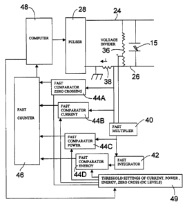
Fig. 2 illustrates diagrammatically the electrical circuitry of the
arrangement
shown in Fig. 1, associated with a fast analog multiplier 40, a fast analog
integrator
42, a fast comparator 44A for zero crossing, 44B for current, 44C for power
and 44D
for energy, a fast counter 46 and a computer 48. As shown in Fig. 2, pulser 28
is
connected by wires 24, 26 to the electrode producing a plasma or corona
discharge
15. The voltage (v) across the grids of the electrode is measured in this case
by a
resistive voltage divider 36 and the current (i) is measured by a current
resistor 38.
The voltage (v) and current (i) are designated herein by lower case letters
because
they are instantaneous values and, as such by convention of electrical
engineering are
written in lower case. The total power at the electrode is then determined by
multiplication P = v x i, by means of the fast analog multiplier 40. The
discharge
duration can be anything between 100 nanoseconds and a few microseconds.
-6-
CA 02365955 2001-12-17
Integrating the product of v x i over time, for example, by means of a fast
analog
integrator 42, will give the energy (e) of a particular discharge. Peak
current, peak
power and peak energy of the discharges are thus available in analog form in
real
time. These outputs are then compared to preselected threshold values, for
example,
by fast comparators 44B, 44C and 44D, which can be high speed differential
comparators producing a standard digital pulse 0-Sv whenever a particular
discharge
parameter, namely peak current, peak power and/or peak energy exceeds a
specified
threshold. These digital pulses can then be counted, for example, by a fast
digital
counter 46 and the obtained numbers forwarded to a computer 48, such as a PC.
The
computer 48, by simple subtraction, can deliver the number of discharges
occurring
between threshold setting #n in 49 and threshold #n + 1. A fast computer 44A
for a
zero crossing channel is also provided to count the total number of
microdischarges
per second to evaluate the overall plasma activity, if desired.
The above described set up, therefore, provides an accurate essentially
instantaneous or real time "photograph" of what happens in the plasma or
corona
discharge reaction. These purely electrical measurements have been found to be
linked to physics and chemistry of the reaction taking place in the plasma or
corona
reactor. For example, the number of microdischarges must be increased when the
flow of input reactant is increased or a number of high energy microdischarges
should
be increased for certain type of reactions, such as dissociation, and the
like.
On this basis, providing a given microdischarge pattern can be implemented
by a PC program following a relatively simple control algorithm, such as:
- Send initial corona voltage, corona frequency, corona pulsewidth values to
electrode via pulser;
CA 02365955 2001-12-17
- Read analyser;
- Modify corona voltage, corona frequency, corona pulse width values
according to discharge distribution;
- Stop when predetermined discharge distribution is attained (within desired
tolerance).
Fig. 3 illustrates the analyser box 50 and its connections in greater detail,
and
Fig. 4 provides a descriptive outline of said connections. The potentiometers
A, B, C
and D are used to adjust threshold voltages within desired ranges.
Potentiometer E is
a spare potentiometer that can be used if one of the others malfunctions. The
banana
plugs A, B, C, D,. E, F, G, H, I, J and K provide connections to various
devices used as
part of the set-up of the present invention. Thus, plugs A, C, E and G connect
to the
digital voltmeter DVM 52 for DC threshold measurements. Plugs B, D, F and H
connect to the frequency counter 54 for discharge counting. The counter 54 in
this
case was of 0-10 Megahertz. Plugs I and K connect to a two channel
oscilloscope 56
1 S for corona voltage and corona current visualization.
The analyser box 50 is also provided with switches for POWER ON/OFF and
VOLTS DIVIDER and is connected to the electrode volts/amps connector 58 which
is
supplied with electrode voltage sense and electrode current sense. The corona
voltage
divider box 60 is also connected to the electrode. Finally, a line filter 62
is provided
for noise suppression.
Fig. 5A and Fig. 5B illustrate typical corona voltage and current waveforms
produced by long pulsewidth, high impedance pulser, and by short pulsewidth,
low
impedance pulser respectively. In both cases, alumina electrodes were used and
the
reactant was air. In both cases, the visual results were obtained by
connecting the
_g-
CA 02365955 2001-12-17
oscilloscope as shown in Fig. 3 and looking at the corona voltage and current
waveforms. It should be noted that voltage and current waveforms represent
instantaneous values of voltages and currents at the electrode and that v is
continuous,
but i is not. The electric current, contrary to conventional electric
circuitry, does not
follow the electrode voltage waveform. The current waveforms are discrete
jumps
which occur randomly, with little correlation to electrode voltage. In other
words, at a
given instant, there can be an electrode voltage, but not current, i.e. no
microdischarge. Moreover, the frequencies of currents are several orders of
magnitude higher than the basic corona frequency. This is due to the fact that
the
electrode is not a mere passive capacitor; during discharge, it behaves Iike a
high
frequency generator. All this can be seen with an oscilloscope. Moreover,
voltage and
current waveforms can vary with pulser characteristics, high voltage
transformer
characteristics, corona pulse width, type of electrode used, type of reactant,
and so on.
Examples of recording the number of discharges with the analyser of the
present invention will now be given.
EXAMPLE 1
Recording the number of discharges as a function of current thresholds can be
done as follows:
- Disconnect oscilloscope;
- Connect DVM to banana plug G (current thresholds values);
- Connect frequency counter to banana plug H (number of discharges having
current above given threshold value, 0.6 Amp/volt);
- Vary threshold values from 0 vdc to 2.5 vdc (0 to 1.5 Amp) by e.g. 10
increments of 0.25v (0.150 Amp) and read on counter n = number of pulses/sec
for
-9-
CA 02365955 2001-12-17
each different level. Record values, which in this example were as follows:
Threshold, volts: Threshold, Amps:Number of discharge above
threshold:
0 0 29334
0.25 0.150 22322
0.50 0.300 15010
0.75 0.450 6789
1.0 0.600 3456
1.25 0.750 123
1.50 0.900 0
1.75 1.050 0
2.0 - -
2.25 - -
2.50 - -
With some error (which can be made as small as wanted by increasing the
number of threshold selected), the number of discharges having currents of for
example 0.075 Amp is 29334-22322 = 7012.
EXAMPLE 2
Recording the number of discharges as a function of power threshold can be
done as follows:
- Disconnect oscilloscope;
- Connect DVM to banana plug B (power thresholds values);
- Connect frequency counter to banana plug C (number of discharges having
power above given threshold value, 9 kilowatts/volt);
- Vary threshold values from 0 vdc to 2.5 vdc (0 to 22.5 kilowatts) by e.g. 10
increments of 0.25v (2.25 kw) and read on counter n = number of pulses/sec for
each
different level. Record values which in this example were as follows:
Threshold, volts: Threshold, kilowatts: Number of discharge above threshold:
0 0 50345
0.25 2.25 30636
0.50 4.50 29048
0.75 6.65 12078
1.0 9 10978
-10-
CA 02365955 2001-12-17
1.25 11.25 560
1.50 13.50 120
1.75 15.75 0
2.0 18 0
S 2.25 20.75 0
2.50 22.5 0
With some error (which can be made as small as wanted by increasing the
number of threshold selected), the number of discharges having powers of for
example 1.125 kw is 50345-30636 = 19709.
EXAMPLE 3
Recording the number of discharges as a function of energy thresholds can be
done as follows:
- Disconnect oscilloscope;
- Connect DVM to banana plug E (energy thresholds values);
- Connect frequency counter to banana plug F (number of discharges having
current above given threshold value, 0.562 Joules/volt);
- Vary threshold values from 0 vdc to 2.5 vdc (0 to 1.4 Joule) by e.g. 10
increments of 0.25v (0.140 J) and read on counter n = number of puises/sec for
each
different level. Record values which in this example were as follows:
Threshold, volts:Threshold, Joules:Number of discharge above
threshold:
0 0 15006
0.25 0.140 12670
0.50 0.280 5678
0.75 0.420 23
1.01 0.560 0
1.25 - -
1.50 - -
1.75 - -
2.0 - -
2.25 - -
2.50 - -
With some error (which can be made as small as wanted by increasing the
-11-
CA 02365955 2001-12-17
number of threshold selected), the number of discharges having energies of
e.g. 0.070
J is 15006 -12670 = 2336.
E3~AMPLE 4
Recording the number of zero crossing discharges can be done as follows:
- Connect DVM at banana plug A and counter at banana plug B.
- Set threshold to about +0.100V.
- Read number of zero crossing discharges on counter.
- Zero crossing discharges can be used to evaluate roughly the plasma
activity.
Patterns obtained by the analyser of the present invention as described above
can be seen as providing plasma electrical signatures, taking into account the
discontinuous nature of microdischarges. Once a given signature corresponding
to
optimum results is known, it can be adopted and reproduced by merely
controlling a
few electrical parameters.
The invention is not limited to the specific embodiments and examples
described above, but includes various modifications obvious to those skilled
in the
art, without departing from the scope of the following claims.
-12-