Note: Descriptions are shown in the official language in which they were submitted.
CA 02366066 2002-05-10
ABSORBENT FILTER MATERIAL MATRICES
AND THEIR ARRANGEMENTS IN FILTER CARTRIDGE
BACKGROUND OF THE INVENTION
This invention relates to a filter cartridge intended primarily for use in
respirators and
airscrubbing equipment.
To avoid inhalation of dangerous vapours, workers may be required to breathe
through a
respirator or other airscrubbing equipment having a filter.
Known systems use an absorbent, wet or dry, such as granular fills, molecular
sieve,
(pleated) filter paper or cloth or other filter material where the air flows
through the porous
filter media. While these systems may be very effective, they provide a very
highly
resistive force, opposing the airflow, resulting in a high pressure drop,
which is especially
detrimental and demanding when used to purify breathing air. The result is
shortness of
breath and little energy left for productive work. A further result is an
uneven exposure of
the interacting surface to the airflow in pleated absorbent porous paper
filters.
Canadian Patent No. 1,265,754 to Rolf Eberl and Adolf Eberl describes several
filter
arrangements where the air flows around the filter material, rather than
through it.
The present invention seeks to further improve filter arrangements.
SUMMARY OF INVENTION
A filter cartridge is described for use in a system to remove impurities from
the air. The
cartridge has a filter section which may provide tortuous air flow channels
between an inlet
and an outlet of the filter section. The filter material may be formed from a
pair of adjoined
sheets with at least one of the sheets having an internally directed raised
pattern thereon.
-1-
CA 02366066 2002-05-10
This raised pattern spaces the adjoined sheets. The adjoined sheets are
positioned in the
cartridge with said sheets paralleling an airflow direction through said
filter section. It is
also contemplated that the raised pattern of the adjoined sheets provide
linear air flow
channels but ones which are less than three millimeters in height.
Alternatively, the filter
section may comprise an open pore sponge or foam. The cartridge may be
provided with an
inlet closure plate having openings therein so as to impart turbulence to
incoming air.
Accordingly, the present invention provides a filter cartridge having a filter
section with a
filter material comprising a pair of adjoined sheets, at least one of said
sheets having an
internally directed raised pattern thereon so as to space said adjoined
sheets, said adjoined
sheets positioned in said cartridge with said sheets paralleling an air flow
direction through
said filter section, said raised pattern providing tortuous paths through said
filter section.
According to another aspect of the present invention, there is provided a
filter cartridge,
comprising: a filter section comprising an open pore sponge.
According to a further aspect of the invention, there is provided a filter
cartridge
comprising: a filter section with tortuous air flow channels extending between
an inlet and
an outlet of said filter section; an inlet closure plate having openings
therein so as to impart
turbulence to incoming air.
According to a yet further aspect of the invention, there is provided a filter
cartridge having
a filter section with a filter material comprising a pair of adjoined sheets,
at least one of said
sheets having an internally directed raised pattern thereon so as to space
said adjoined
sheets, said adjoined sheets positioned in said cartridge with said sheets
paralleling an air
flow direction through said filter section, said raised pattern providing
linear parallel flow
paths through said filter section, said raised pattern providing a spacing of
less than three
millimeters between said pair of adjoined sheets.
-2-
CA 02366066 2002-05-10
BRIEF DESCRIPTION OF THE DRAWINGS
In the figures which describe example embodiments of the invention,
figure 1 is a vertical cross section of a filter cartridge, showing the
location and placement
of filters, spacers and diffusing shield and wicks, as well as entry and exit
ports of the
container,
figure 2 is a horizontal cross section of a filter cartridge, showing the
placement of the star-
shaped separator, the diffusing discs and the entry and exit ports,
figure 3 is a top view of a rolled up corrugated filter section with
distributed wicks,
figure 4 is a perspective view of a lower separator, showing placement of the
holes and the
steps on which a deflecting disc rests and is centered,
figure 5 is a perspective view of a known filter section, made out of two
sheets of absorbent
material, one sheet is straight and one corrugated, rolled up together,
figure 6 is a vertical cross section of a known filter cartridge of having
filter discs, with the
separator strips omitted for clarity,
figure 7 is a broken away perspective view of one of the filter discs (26 of
figure 7, 8) and
its positioning in a container via a double ridge,
figure 8 is a vertical cross section of another known filter cartridge having
filter discs, with
separator strips not shown for clarity,
figure 9 is a perspective view of a second filter disc of figure 8,
figure 10 is a perspective view of a first filter disc of figure 8 and part of
the container,
showing the double ridge and its guiding action for a disc,
figure 11 is a perspective view of a filter section of a filter cartridge
according to a first
embodiment of this invention,
figure 12 is a perspective view of a portion of the filter material of the
filter section of
figure 11,
figure 13 is a perspective view of a filter section of a filter cartridge
according to a second
embodiment of this invention,
figure 14 is a perspective view of a portion of another embodiment of filter
material for a
filter section,
figure 15 is a perspective view of a portion of a further embodiment of filter
material for a
filter section,
-3-
CA 02366066 2002-05-10
figure 16 is a perspective view of a filter section of a filter cartridge
according to a further
embodiment of this invention,
figure 17 is a simplified perspective view of a closure plate for the inlet
side of a filter
section, and
figure 18 is a simplified perspective view of another closure plate for the
inlet side of a
filter section.
DETAILED DESCRIPTION
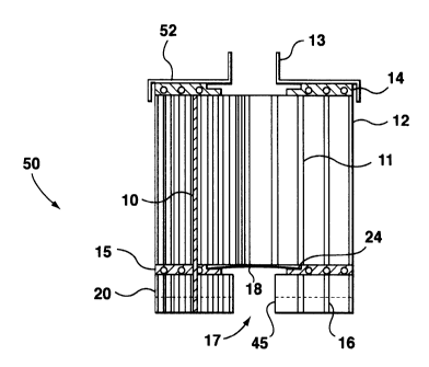
Turning to figures 1 to 4, a filter cartridge 50 has, within a container
(canister) 12, in
downstream order, an inlet port 17 opening to a short pipe section 45 defined
by an inlet
filter section 16 (that functions as a water reservoir to replace lost
moisture), a separator 15
with a deflection disc 18, a primary filter section 11, and a separator 14
with a top cover S2
and an outlet port 13. The base of the inlet filter section is filled with
liquid to liquid level
20. Wicks 10 are distributed through, and extend between, the inlet 16 and
primary 11 filter
sections.
Pipe section 45 at the bottom of the container is composed of a 35 mm diameter
pipe,
extending upwaxds into the container 12 by about 50 mm resulting in a
reservoir that retains
the excess liquid needed to humidify the airflow and to keep the main
absorbent filter 11
moist. To facilitate this, a short absorbent filter section 16 (about 50 mm
high) rests on the
floor of the container where the reservoir is, absorbing part of the excess
liquid and
retaining the balance of the not yet absorbed fluid.
Held above this lower absorbent assembly by a well perforated separator 15
(figures 2 and
4) is the second (about 120 mm high) main filter section 11. The separator
should preferably
(but not necessarily) be star-shaped, made from a 20 mm wide band of stiff
material,
standing on its edge. The inner hub of the separator is a little larger in its
diameter than the
inlet port. The outgoing spokes of the star are notched on the upper inner
edge to create a
round recess, that holds in place an inverted saucer shaped diffusing disc
that deflects and
distributes the airflow more evenly.
-4-
CA 02366066 2002-05-10
Strategically spaced wicks 10 (figures 1 and 3) can be inserted in some of the
corresponding channels, spanning the gap between the upper and lower absorbent
filter
sections, to achieve better replacement of evaporated liquid in the upper
filter section.
A second separator 14, similar to the first, placed on top of the main
absorbent filter 11,
assures proper positioning and spacing of the main absorbent filter 11 at the
top of the
container 12. If a particle filter is needed, it can be fitted to the bottom
of the container in
an additional container, fastened airtight with tape or gasket or latch-
fasteners.
The absorbent filter sections 11 and 16 are designed in such a way that they
have vertically
running channels.
This system can be paired with an extra particle, carbon or electrostatic
filter annex.
Referencing figure 5, the absorbent of filter section 11 (or 16) can be made
from a variety
of porous or fibrous materials - such as filter, blotting, ceramic paper or
fiber mats from
natural or synthetic origin, as well as ceramic or sintered materials, woven
fabric, paper or
sheet materials. The absorbent is manufactured into a matrix of a plurality of
parallel
channels 3, facing the airflow with its openings. This produces an airflow
parallel to the
surface of the channels and gives the air time to exchange vapours by defusing
chemicals
and removing impurities with little pressure drop.
To achieve this a corrugated 5 and a straight 6 sheet are joined together like
a single-sided
corrugated cardboard, by gluing, pressing, ultrasonic or diathermic welding,
heatsetting, or
any convenient way. The corrugation can be made sinusoidal, triangular, square
or
trapezoidal. The resulting corrugated absorbent is then rolled up tightly to
fill the canister
12 which can be round, oval, kidney or any other convenient shape to fit the
purpose.
Pressed carbon, sintered materials or porous ceramic materials can also be
processed the
same way, or can be pressed into a solid form with fine longitudinal parallel
channels (or
holes) with very thin walls by a mold, to end up with a similar arrangement as
the
corrugated absorbent.
-5-
CA 02366066 2002-05-10
Some organic or synthetic fibers, once arranged into a matrix, can be
carbonized completely
or partially under controlled conditions as known in the art. This can be done
before or
after impregnation with salts, reagents, chemicals, catalysts or a mixture of
two or more of
the before mentioned.
In most cases the absorbent is saturated with liquids just before being put to
use, to activate
the filter to attract, trap, transform, diffuse or absorb vapours, chemicals
or particles and
impurities from the contaminated airflow.
In the case of a dry absorbent system of the corrugated variety or the solid
channelled form,
silicagel can be used to extract water or other fluids and vapours.
In use, the airflow enters via the entry port 17 (figure 1), hits the
deflection disc 18, fans out
and distributes through the holes in the spokes of separator 15, picks up
moisture and
exchanges vapours, and also loses particles as it passes through the multitude
of parallel
channels (figure 1, 5). The slow moving air passes over the tremendously
expanded surface
of the channels 3 (figure 5), saturated with liquids or chemicals and not
through the porous
material itself to achieve: diffusion, exchanges, absorption, cracking,
isotopic exchanges
and conversions, chemical reactions or chemical conversions. The air flowing
through
those symmetric and well organised channels 3 of equal size and length with
also cause a
fairly uniform air velocity, giving the air uniform chemical exchange and
reaction time.
To keep filter 11 moist, filter 16 absorbs liquid from the liquid level 20 and
gives moisture
off through evaporation as well as via the multitude of wicks 10 to filter 11
by capillary
action. Shaking, as well as movement (while working) will also distribute the
liquid.
Filters 11 and 16 are manufactured from rolled up single-sided corrugated
filter material or
pressed carbon, sintered materials or porous ceramics as mentioned before.
A second known arrangement illustrated in figures 6 and 7, has a container 12,
with inlet
port 17, short pipe section 45, top cover 31 and outlet port 13 similarly to
the arrangement
of figures 1 to 4. The canister 12 is built as in the first arrangement,
except that it should
be round.
-6-
CA 02366066 2002-05-10
The absorbent can be the same material as in the first arrangement. It can
also be treated
similarly, but the channels are created differently.
Three stacks of equally sized filter discs are used. Section 41 at the bottom
of the container
is filled with discs 26, retaining liquid and transporting the liquid from
waterline 20 up to
the second and actual filter pack, section 42, by capillary action. Also, the
liquid sloshes by
movement (such as work). Thus, the replacement of evaporated fluids from the
discs 26 is
accomplished by a capillary action as well as by sloshing as the user moves
when working.
This filter discs of stacks 41, 42, and 43 can be manufactured as described in
the first
arrangement, with the same materials and the same chemical and fluid
treatment, or it can
also be used dry, made with silicagel. The absorbent disc material used can be
made in
different thicknesses, depending on the properties of the different materials,
in this case it is
about 1 to 2 mm. The discs are made of thin absorbent filter material, of
about 100 mm to
1 S 150 mm diameter with a 35 mm hole in the middle. On top of the disc,
running radially
from center hole to outer edge, and evenly distributed, are a multitude (nine
to fifteen) of
separator strips, 32, about 3 to 6 mm wide and I to 3 mm high, pointed on the
inside end to
improve the airflow, and protruding beyond the outer edge of the disc about 6
mm to touch
the walls of the round rust-proof respirator canister. The protruding
separator strips will
center the disc, creating a cylindrical space, 29, that surrounds the stacked
filter discs, for air
to flow upward to the third filter stack, section 43. Short separator strips
33 of half length
are placed alternating with the long ones 32 and center the disc and separate
the discs, so
that air can flow through the space between discs in the stack. The shorter
separator strips
33 have the same height as strips 32 and run radially to the outer edge of the
disc, but not to
extend beyond the outer edge. By placing the long and short separator strips
respectively on
top of each other (with help of the double ridge) the stack becomes more rigid
and improves
the capillary action of the stack.
The second stack, section 42 is terminated by disc 27, with the same
construction as disc 26
but without the center hole so as to cover the distribution chamber 28.
Because of disc 27, the air in section 42 has to flow radially outwards
through the multitude
of fine channels created by the stacked discs and their separators.
CA 02366066 2002-05-10
The air coming through the input port at the bottom flows up into the
distribution chamber,
28. From there the air enters all the spaces between the discs of stack 42 and
will flow
radially outward to join again in the cylindrical airspace 29, surrounding all
the discs, 26
S and 27. Flowing up space 29 until it reaches stack 43, the air enters the
spaces between the
filter discs of stack 43, flowing radially inward, joining again in the
collecting chamber 30,
to exit via the outlet port 13.
If the porous filter material used for the discs will not sag or soften and
the container is fully
packed without slack, the spring 31 may not be necessary. Otherwise spring 31
compresses
the discs downwardly and takes up the slack.
As in the first arrangement, in the second arrangement the chemical exchanges,
diffusions,
vapour exchanges and all other air cleaning reactions can be the same and
occur as the air
flows along the porous, absorbent filter material - and not through it.
As in the first arrangement, a particle filter can be added to the inlet side
of the canister.
In a third known arrangement shown in figures 8 to 10, the same filter
materials and
reactions can be used as in the first two arrangements. The container 12 is
the same as in
figure 6. The reservoir is filled as in figure 1 with a rolled up single-sided
corrugated filter
16 with a separator 1S (with holes 19) as in figure 1. On top of the
perforated, star-shaped
separator is a stack of filter discs, composed of two different discs 37,
detailed in figure 9,
and 36, detailed in figure 10.
Discs 36 and 37, figure 9 and figure 10, are made similarly to disc 26 of
figure 7, with the
difference that separator strips 32, 33 and 35 are made thicker, about 3 mm to
6 mm high,
depending on the results to be achieved. Also filter disc 36, figure 10 has no
center hole.
Disc 37, figure 9 is bigger and the thin filter material extends out to and 1
mm beyond the
edge of the separators 33 and 35, which are the exact diameter of the
container minus %2
mm. This produces a snug fit and keeps air from flowing past.
_g_
CA 02366066 2002-05-10
The first disc of the stack is of the smaller disc type, 36, followed by the
larger disc, 37, and
alternating thus all the way to the exit port. It is of no importance which
type of disc tops
the filter stack. The double notch 39 on disc 37, as well as separator 32 of
figure 10 on disc
36 and the double ridge 38 (figure 7) keep the separator strips aligned one
over the other.
Thus, the absorbent filter disc stack is composed alternately of discs with a
35 mm hole in
the center and the outside diameter the same as in the cylindrical container
and smaller filter
disc 36 with no hole in the center. In this arrangement, the larger disc 37
has about 6 mm
wide and 6 mm high separator strips on top, spaced equally and running
radially outward
from the hole to the outer edge. The second disc is about l2mm smaller in its
diameter than
the container, with 6 mm wide and high separator strips, running radially from
an imaginary
inner circle of about 35 mm diameter and protruding over the outer edge by 6
mm centering
the smaller disc. Aligning the alternating discs, so that the spacing
separator strips come to
rest on top of each other, can be accomplished by a double ridge running down
one side of
the inside of the container, 6 mm apart, to accommodate one of the separator
strips of the
discs. On the larger discs 37 a small notch 39 (figure 9) on either side on
one of the
separator strips 33 will locate on the double ridge 38 (figure 7).
The air entering at 17, flowing through separator 15 and through holes I9,
picks up moisture
from absorbent fill 16, hits the wall and turns to flow inward between disc 36
and disc 37,
entering the hole of disc 37 and passes radially outward between the first
disc 37 and the
second disc 36, alternately flowing in and out, till reaching the top and
exiting via the outlet
port. All chemical and physical air cleaning action is the same as in the
first two
arrangements.
In this system of alternating absorbent filter discs, the air coming through
the bottom entry
port has to "weave" its way in and out through the alternating discs,
accomplishing a longer
interaction between the flowing air and the parallel surfaces of the
absorbent. By choosing
the right number of discs and the right separation of the discs one can
balance out the right
compromise between pressure drop and air cleaning efficiency.
-9-
CA 02366066 2002-05-10
As in the first two arrangements, the bulk of the air does not flow through
the holes in the
porous filter material, but parallel to the filter media. After flowing
through all of the
stacked discs, the air exits via the outlet port at the top of the container.
S The filter sections of the described arrangements may be changed to improve
the
efficiencies of the canister filter system. More specifically, filter sections
11 and/or 16 may
be replaced by the filter section 60 of figures 11 and 12. Filter section 60
is fabricated in
the same way as described for filter section 11 of figure 5 and is inserted
into a filter
canister 12 (figure 1) such that its channels 3' parallel the air flow through
the canister.
However, the channels 3' of the filter section 60 are made smaller. More
particularly, the
channels are made as microgrooves to increase the surface area of the filter
that any given
volume of air is in contact with as it passes through the filter. Previous
arrangements use
channels approximately 3 mm thickness from layer to layer. The microgroove
arrangement
requires that the layer to layer distance be less than 3 mm (dimension "X",
figure 12).
1S
In a variation illustrated in figure 13, the rnicrogrooves 3" of filter
section 70 have multiple
changes in direction such as are created with zig-zag channels or other
patterns which
generate turbulence in the air as it passes through the filter medium.
Rather than fabricating filter section 60 as a back sheet joined to a
corrugated sheet, a
modified filter section may be fabricated as illustrated in figure 14. Dimples
74 may be
pressed into the sheet stock used to form the filter matrix to cause the
adjoining surfaces to
be spaced away from the separating layer 76 as to create a gap between layers.
2S Optionally, dimples (as in figure 14) may be pressed into the sheet stock
and adjoined to
another layer with offset dimples to form the filter matrix through which the
air must pass
with layers spaced by the dimples from adjoining surfaces to create the
channels.
Also, other raised patterns may be pressed into the sheet used to form the
filter matrix to
cause the adjoining surfaces to be spaced away from the adjoining layers to
create channels
with increased turbulence and to increase the contact the air has as it passes
through in its
passage through the filter.
- 10-
CA 02366066 2002-05-10
As a further option, filter section 60 may be fabricated of an open pore
sponge or foam 84
adhered to a separator sheet 86 as in figure 15 made of an absorbent foam
through which air
can flow in random and turbulent fashion past surfaces of sponge. It will be
appreciated
that the sponge material may be of a man-made or natural fibre such as paper,
cellulose, or
other plant fibre formed in to a self supporting lattice through which air can
flow. The
separator sheet may be impregnated with the water or other solution.
In figures 11 and 13, the sheets of the filter material is illustrated as
being rolled up into a
spiral. As described, this filter material is then positioned in the canister
12 so that the
sheets parallel the airflow direction through the filter section. However, as
will be obvious
to one skilled in the art, equally, individual sheets of filter material could
be stacked side-
by-side and positioned edge on to the direction of the air flow so as provide
sheets which
parallel the airflow direction through the filter section.
A filter material having dimples or other raised patterns as described, or a
filter material
having the described open pore sponge adhered to a back sheet, may also be
used as the
filter material for the disc filters 26 of figure 6 or 36 or 37 of figures 8
to 10.
With reference to figure 16, filter sections 11 or 16 may also be replaced
with a filter
section 90 being an artificial open pore sponge made of an absorbent foam
through which
air can flow in random and turbulent fashion past surfaces of sponge
impregnated with the
water or other solution.
More generally, it has been recognised that a filter matrix manufactured of a
paper-like
material, or paper thin sheet of man-made material, which due to fibers or
surface
preparation, increases the surface area exposed and turbulence of the
tritiated water vapour
as it passes through the filter provides enhanced efficiency.
Also, by the expedient of increasing the length of the filter section of
figures 1, 6, or 8 to
provide a path length of twenty millimeters or more, higher efficiencies may
be obtained
than previously known.
-11-
CA 02366066 2002-05-10
Optionally, a closure plate 92 (figure 17) may be provided on the inlet side
of the filter
section. The closure plate has small openings 94 which enhance the turbulence
of the in-
rushing air and, therefore, increase filter efficiency. Turbulence might be
even further
increased by providing irregularly shaped small openings in the closure plate.
Alternatively, turbulence may be increased by providing deflectors 96
associated with the
openings 94, in the closure plate 92' shown in figure 18.
The openings in the closure plate may be punch formed or otherwise formed.
The filter medium may be impregnated with activated charcoal or other
substance to
increase the shelf life or suppress the growth of bacteria or moulds on the
filter matrix.
Filters of the described arrangements are specially suited for the removal of
tritiated water
vapours, isotopic exchanges and catalytic reactions. For example 99.8% of
tritiated water
vapours have been removed during a two hour period.
As will be apparent to those skilled in the art, optionally, any of the
described filter
cartridges may be manufactured without the inlet filter section 16 (i.e., the
cartridges may
not have a water reservoir).
Other modifications than those described will be apparent to those skilled in
the art and,
therefore, the invention is defined in the claims.
-12-