Language selection

Search

Patent 2366133 Summary

Third-party information liability

Some of the information on this Web page has been provided by external sources. The Government of Canada is not responsible for the accuracy, reliability or currency of the information supplied by external sources. Users wishing to rely upon this information should consult directly with the source of the information. Content provided by external sources is not subject to official languages, privacy and accessibility requirements.

Claims and Abstract availability

Any discrepancies in the text and image of the Claims and Abstract are due to differing posting times. Text of the Claims and Abstract are posted:

  • At the time the application is open to public inspection;
  • At the time of issue of the patent (grant).
(12) Patent: (11) CA 2366133
(54) English Title: VEHICULAR EXHAUST PIPE WITH ILLUMINATING DEVICES
(54) French Title: TUYAU D'ECHAPPEMENT AVEC DISPOSITIFS LUMINEUX POUR VEHICULES
Status: Deemed expired
Bibliographic Data
(51) International Patent Classification (IPC):
  • B60Q 1/26 (2006.01)
  • F01N 13/08 (2010.01)
  • F21V 33/00 (2006.01)
(72) Inventors :
  • CHEN, KUO-TAI (Taiwan, Province of China)
(73) Owners :
  • CHEN, KUO-TAI (Taiwan, Province of China)
(71) Applicants :
  • CHEN, KUO-TAI (Taiwan, Province of China)
(74) Agent: BATTISON WILLIAMS DUPUIS
(74) Associate agent:
(45) Issued: 2005-03-08
(22) Filed Date: 2001-12-21
(41) Open to Public Inspection: 2003-06-21
Examination requested: 2001-12-21
Availability of licence: N/A
(25) Language of filing: English

Patent Cooperation Treaty (PCT): No

(30) Application Priority Data: None

Abstracts

English Abstract


An exhaust pipe with illuminating devices is formed by an inner pipe enclosed
in an
outer pipe. A gap is formed in between the two pipes. The gap comprises a
light
socket connected to at least one illuminating device. The light socket and the
illuminating device are connected by means of an electric cord. The outer pipe
comprises
holes on its wall. When the illuminating devices are lighted, the light will
shine from
the tail end and the holes of the exhausting pipe either directly or
reflectively


Claims

Note: Claims are shown in the official language in which they were submitted.


I CLAIM:

1. A vehicular exhaust pipe with illuminating devices, comprising an inner
pipe
closed in an outer pipe, and forming a gap there between, and being
characterized in
that:
said gap comprising at least one light socket being connected to at least one
illuminating device, said light socket and said illuminating device being
connected by means of an electric is cord, wherein when said illuminating
device
being turned on, the light will shine through the tail of said exhaust pipe
directly or reflectively.
2. The vehicular exhaust pipe with illuminating devices, as recited in claim
1,
wherein a controlling device is ceded between said electric cord and said
illuminating
device to tum on and off said illuminating device.
3. The vehicular exhaust pipe wide illuminating devices, as recited in claim
1,
wherein said outer pipe comprises holes on its wall for light to emit there
from.
4. The vehicular exhaust pipe with illuminating devices, as recited in claim
1,
wherein said illuminating devices have the same color or different colors.
5. The vehicular exhaust pipe with illuminating devices, as recited in claim
1,
wherein said light socket has more than one unit.


5

Description

Note: Descriptions are shown in the official language in which they were submitted.


CA 02366133 2001-12-21
"~
TTTLE: VEHICULAR EXHAUST PIPE WITH ILLUMINATING DEVICES
Background of the Invention
Field of the Invention
This invention relates to a vehicular exhaust pipe, more particularly to a
pipe with
s illuminating devices.
Description of Prior Art
A conventional exhaust pipe of any vehicle exhaust pipe is made of metal
material,
it is made to guide waste gas produced from the engine and the cylinder into
the air. This
pipe is a plain outfit and has no arty design.
io In order to build a more attractive and fancy appearance, tip inventor has
invited
the present invention.
Swnmary of the Invention
It is the primary object of the present inv~tion to provide an ~ pipe for a
vehicle, which enables to illuminate light from the exhaust pipe to make it
more
is attractive.
It is another object of the present invention to provide an exhaust pipe for a
vehicle,
which emits light from the exhaust pipe as a warning to people from being
hurt.
Brief Description of the Drawings
FIG. 1 is a perspective view of the present invention;
t


CA 02366133 2001-12-21
FIG. 2 is a side cross sectional view of FIG. 1;
FIG. 3 is a side cross sectional view of a second embodiment of the present
invention; and
FIG. 4 is a perspective view of a third embodiment of the present invention.


CA 02366133 2001-12-21
Detailed Description of the Preferred Embodiment
The exhaust pipe with illuminating devices of the present invention, as shown
in FIG.
1, comprises an inner pipe 1 being secured within an outer pipe 2 by means of
f11
to form a gap 3 between the two pipes 1 and 2.
The gap 3 has a light socket 4 and at least one illuminating device 5 secured
therein.
The light socket 4 and the illuminating device 5 am connected to each other by
an electric
cord 6. A cor~olling device (not shown in the drawings) is connected in tithe
illuminating device S and tl~ electric coed 6 to tom the illuminating device 5
on and off in
sequence or in egularly
io As shown in FIG. 2, this design will dic~ect or reflect the light from the
illwninating
device 4 in the gap 3 to the pipe tail to form a light circle. If the electric
cord 6 is cormected
to a brake light system, the light may provide an extra warning signal. If
there is more
than one illuminating device 5, a different color may be applied.
The outer pipe 2, as shown in FIG. 3, may be formed with holes 21 on its wall
for the
is light from the illuminating device 5 to shine through.
The above said is applied one light socket 4 connected to at least one
illuminating
device 5. The light socket 4 and the illuminating device 5 may be added, as
shown in
FIG. 4. A pair of light sockets 4 and 4' are applied with one socket at the fi
ont and the
other at the rear end in the gap 3. In this figure, there is a hole 41' for
the light of the
2o illuminating device 5 to shine through.
With the design of the inner pipe 1 enclosed in the outer pipe 2, the gap 3
will be in a
dark place, thus when the illuminating device 5 toms on plus the exhaust pipe
tail lighting,


CA 02366133 2001-12-21
an att<active effect is produced. If the electric cord 6 is connected to the
brake light
system, the illuminating device S may be treated as a wanvng brake signal.
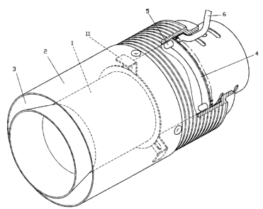
Representative Drawing
A single figure which represents the drawing illustrating the invention.
Administrative Status

For a clearer understanding of the status of the application/patent presented on this page, the site Disclaimer , as well as the definitions for Patent , Administrative Status , Maintenance Fee  and Payment History  should be consulted.

Administrative Status

Title Date
Forecasted Issue Date 2005-03-08
(22) Filed 2001-12-21
Examination Requested 2001-12-21
(41) Open to Public Inspection 2003-06-21
(45) Issued 2005-03-08
Deemed Expired 2006-12-21

Abandonment History

Abandonment Date Reason Reinstatement Date
2003-12-22 FAILURE TO PAY APPLICATION MAINTENANCE FEE 2003-12-31

Payment History

Fee Type Anniversary Year Due Date Amount Paid Paid Date
Request for Examination $200.00 2001-12-21
Application Fee $150.00 2001-12-21
Reinstatement: Failure to Pay Application Maintenance Fees $200.00 2003-12-31
Maintenance Fee - Application - New Act 2 2003-12-22 $50.00 2003-12-31
Final Fee $150.00 2004-10-13
Maintenance Fee - Application - New Act 3 2004-12-21 $50.00 2004-12-10
Owners on Record

Note: Records showing the ownership history in alphabetical order.

Current Owners on Record
CHEN, KUO-TAI
Past Owners on Record
None
Past Owners that do not appear in the "Owners on Record" listing will appear in other documentation within the application.
Documents

To view selected files, please enter reCAPTCHA code :


To view images, click a link in the Document Description column. To download the documents, select one or more checkboxes in the first column and then click the "Download Selected in PDF format (Zip Archive)" or the "Download Selected as Single PDF" button.

List of published and non-published patent-specific documents on the CPD .

If you have any difficulty accessing content, you can call the Client Service Centre at 1-866-997-1936 or send them an e-mail at CIPO Client Service Centre.


Document
Description 
Date
(yyyy-mm-dd) 
Number of pages   Size of Image (KB) 
Representative Drawing 2002-03-22 1 16
Cover Page 2003-05-30 1 40
Abstract 2001-12-21 1 15
Description 2001-12-21 4 84
Claims 2001-12-21 1 31
Drawings 2001-12-21 4 84
Cover Page 2005-02-03 1 43
Assignment 2001-12-21 2 75
Fees 2003-12-31 2 46
Correspondence 2004-10-13 1 33