Language selection

Search

Patent 2366280 Summary

Third-party information liability

Some of the information on this Web page has been provided by external sources. The Government of Canada is not responsible for the accuracy, reliability or currency of the information supplied by external sources. Users wishing to rely upon this information should consult directly with the source of the information. Content provided by external sources is not subject to official languages, privacy and accessibility requirements.

Claims and Abstract availability

Any discrepancies in the text and image of the Claims and Abstract are due to differing posting times. Text of the Claims and Abstract are posted:

  • At the time the application is open to public inspection;
  • At the time of issue of the patent (grant).
(12) Patent: (11) CA 2366280
(54) English Title: METHOD OF PRODUCING CHAINSAW CHAIN ALLOWING TO INCREASE THE EFFECTIVENESS OF THE WOODCUTTER IN MODIFYING THE CUTTER LINKS AND SOME SAFETY LINKS
(54) French Title: METHODE DE FABRICATION D'UNE CHAINE DE SCIE A CHAINE QUI PERMET D'AMELIORER L'EFFICACITE DE LA SCIE GRACE A LA MODIFICATION DES MAILLONS-GOUGES ET DE CERTAINS MAILLONS DE SECURITE
Status: Deemed expired
Bibliographic Data
(51) International Patent Classification (IPC):
  • B23D 65/00 (2006.01)
  • B27B 17/00 (2006.01)
  • B27B 33/14 (2006.01)
(72) Inventors :
  • DUQUET, GERMAIN (Canada)
(73) Owners :
  • DUQUET, GERMAIN (Canada)
(71) Applicants :
  • DUQUET, GERMAIN (Canada)
(74) Agent: NA
(74) Associate agent: NA
(45) Issued: 2005-12-27
(22) Filed Date: 2001-12-28
(41) Open to Public Inspection: 2003-06-28
Examination requested: 2003-01-13
Availability of licence: N/A
(25) Language of filing: English

Patent Cooperation Treaty (PCT): No

(30) Application Priority Data: None

Abstracts

English Abstract


A safety saw chain for chain saw and more particularly to the configuration
of drive links and cutter links so as to get a high cutting power, to decrease
the vibration, kickback, and the friction of the saw chain on the guide bar.


Claims

Note: Claims are shown in the official language in which they were submitted.


CLAIM(S):

The embodiments of the invention for which an exclusive property or
privilege as claimed, are defined as follows:

1. A saw chain for chain saw comprising cutter links and drive links
interconnected together by connector links and rivet, wherein each cutter
link includes:
a rocker portion formed with an upper surface provided with two transverse
grooves enabling to free the saw-dust of the saw chain,
a longitudinal furrow reducing the side movement of the cutter link by it
keeping in a longitudinal direction for facilitating a wood-cutting more
deep,
a thinning side surface to decrease the force of impact on the rocker portion
having its angle lightly inclined inwardly of the cutter link for decreasing
the side movements of the cutter link and the retreat effect, and
a side cutting edge defining an oblique angle for decreasing the vertical and
longitudinal vibration of the saw chain, and the retreat effect caused by the
friction of the saw chain in a kerf cut.

2. The saw chain as defined in claim 1, wherein, each drive link is
formed with an upper surface lightly rounded along its length for getting

7


a better evacuation of the saw-dust and effectiveness of the wood-cutting.

8

Description

Note: Descriptions are shown in the official language in which they were submitted.


CA 02366280 2005-05-26
Method of producing ehaita,saw chain alaowing to increase the effectiveness
of the woodcutter in modifying the cutter links and some safety links
BACKGROUND OF' THE INVENTION
Field of the invention:
The present invention relates to a safety saw chain for chain. saw and
more particularly to the configuration of drive links and cutter links so as
to
get a high cutting power, to decrease the vibration, kickback, and the
friction of the saw chain on the guide bar.
Description of the related art:
A search of prior art xecords has unveiled the following patents:
1. CA 1,195,21.1 issued in 1985 to Landwehr;
2, CA 627238 issued in 1961 to August;
3. CA 651448 issued in 1962 to August;
4. US 4,088,047 issued in 1978 to Ratz and al.;
5. US 4,567,$03 issued in 1986 to Andexson;
6. US 4,756,221 issued in 1988 to Nitschrnaratt az~d al.; and
7. US 4,414,876 issued in 1983 to Loigerot.
The patent to Rata is probably the most relevant. As can be seen, the
patent to Ratz shows a method of producing cutting teeth for a chain saw
1


CA 02366280 2005-05-26
each of which has a base body and a tooth roof, and in which the base body
is cranked along a substantially shazp edge relative to tooth roof.
The gist of the invention is therefore to provide a saw chain with a simple
configuration so as to get a high cutting power, to decrease the vibration,
kickback, and the friction of the saw chain on the guide bar.
Summary of the invention:
The present invention describes a safety saw chain for chain saw including
cutter links and drive links interconnected together by connector links and
rivet. Each cutter link includes a cutting tooth portion formed with a top
plate portion, a side plate portion and a front portion defining a side furrow
enabling the cutter link to keep its angle ofpenettation because of the sharp
edges of cutting tooth portion facilitating to go through the wood.
The cutter top plate portion is bent over at an angle relative to side plate
portion. The x~ar region of cutting tooth portion is lightly curved inwardly
of the cutter link.
The depth gauge link is formed with the body portion, cutter portion and
rocker portion. The rocker portion includes an upper surface provided
with two transverse grooves enabling to free the saw-dust of the saw chain,
and a longitudinal furrow reducing the side movement of the cutter link by
2


CA 02366280 2005-05-26
it keeping xn a longitudinal direction for facilitating a wood-cutting more
deep,
The thickness of rockex do the side surface decreases the force of impact on
the rocket portion, and its angle lightly inclined inwardly of the cutter link
decreases the side movements of the cutter link and the retreat elect, by
example the cutting of branches close to the tm.~z~k.
The side cutting edge of rocker is defined by an oblique angle decreasing
the vertical and longitudinal vibration of the saw chain, and the retreat
elect
caused by the frictxoz~ of the saw chain in a kerf cut.
Each drive link having an upper surface lightly rounded along its length, is
configured so as to get a bettex evacuation of the saw-dust and effectiveo,ess
of the wood-cutting.
Advantages of the invention:
- Maintenance less ;
- Mare safe;
- Increase the chain, chainsaw and guide bar durability;
- Increase the sharpening durability;
- Increase the woodcutter;
- Diminution of the gasolxoe and oil consumption;
3


CA 02366280 2005-05-26
- Diminution of the vibration and kickback;
- Diminution of physique effort;
- Diminutaoz~ of chainsaw derailment; and
- Diminution of the rejection of saw-dust twig in the visor.
Brief description of the several views of the d~awnnft(s):
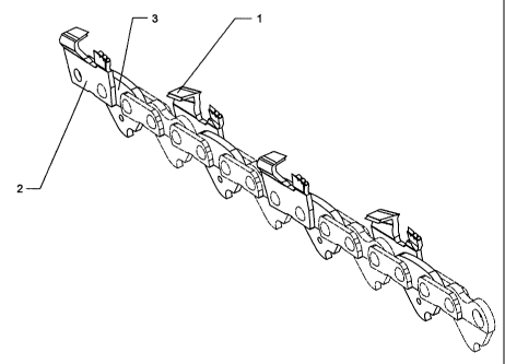
Figure 1 shows a left side perspective view of a saw chain having drive
licks arid cutter links in accordance with the present invention.
Figure 2 shows a right side perspective view thereof.
Figure ~ shows ate exploded view thereof,
Figure 4 shows a left side perspective view of a cutter link.
Figure 5 shows a right side perspective view thereof.
Figure 6 shows a front view thereof
Figure 7 shows a perspective view of a drive link.
Detailed description of the inventionm
Referring to the drawings, and more particularly to figs. 1 to 7, a safety saw
chain for chain saw including cutter links (2) and drive links (3)
interconnected together by contzector links and rivet shown in phantom
lines.
Each cutter link (2) includes a cutting tooth poz~txon (1) formed with a top
4


CA 02366280 2005-05-26
plate portion, a side plate portion (8) and a front portion defining a side
furrow (9) enabling the cutter link to keep its angle of penetration because
of the sharp edges of cutting tooth portion facilitating to go through the
wood.
The cutter top plate portion is bent over at an angle relative to side plate
portion (8). The rear region of cutting tooth portion is lightly curved
inwaxdly of the cutter link (~).
The depth gauge link is formed with the body portion, cutter portion and
rocker portion. The rocker portion includes an upper surface provided
with two transverse grooves (4) enabling to free the saw-dust of the saw
chain, and a longitudinal furrow (~) reducing the side movement of the
cutter link by it keeping in a longitudinal direction for facilitating a
wood-cutting more deep_
The thickness of rocker on the side face (6) decreases the force of impact
on the rocker portion, and its angle lightly inclined inwardly of the cutter
liz~l~ decreases the side movements of the cutter link and the retreat e~Fect,
by e~a~rnple the cutting of bran.ehes close to the trunk.
'hhe side cutting edge (7) of rocker is defined by an oblique angle
decreasing the vertical and longitudinal vibration of the saw chain, and the


CA 02366280 2005-05-26
retreat et~ect caused by the friction of the saw chain in a kerf cut.
Each drive link (3) having an upper surface lightly xounded along its length,
is configured so as to get a better evacuation of the saw-dust and
el~ectivex~ess of the wood-cutting.
Although only a single embodiment of the present invention has been
described and illustrated, the present invention is not limited to the
features
of this embodiment, but includes all variations and modif cations wxtltin the
scope of claims.
Legend
1: Cutting tooth
2: Cutter link
3: give link
4: Garooves of the rocker
: Longitudinal furrow of the rocket
6: Thinning side face of the rockex
7: Side cutting edge of the rocker
g: Side plate portion of the cutting tooth
9: Side furrow of the cutting tooth
10: Upper surface of the drive link
6

Representative Drawing
A single figure which represents the drawing illustrating the invention.
Administrative Status

For a clearer understanding of the status of the application/patent presented on this page, the site Disclaimer , as well as the definitions for Patent , Administrative Status , Maintenance Fee  and Payment History  should be consulted.

Administrative Status

Title Date
Forecasted Issue Date 2005-12-27
(22) Filed 2001-12-28
Examination Requested 2003-01-13
(41) Open to Public Inspection 2003-06-28
(45) Issued 2005-12-27
Deemed Expired 2010-12-29

Abandonment History

Abandonment Date Reason Reinstatement Date
2003-12-29 FAILURE TO PAY APPLICATION MAINTENANCE FEE 2004-09-16

Payment History

Fee Type Anniversary Year Due Date Amount Paid Paid Date
Application Fee $150.00 2001-12-28
Request for Examination $200.00 2003-01-13
Reinstatement: Failure to Pay Application Maintenance Fees $200.00 2004-09-16
Maintenance Fee - Application - New Act 2 2003-12-29 $50.00 2004-09-16
Maintenance Fee - Application - New Act 3 2004-12-28 $50.00 2004-12-06
Final Fee $150.00 2005-10-19
Maintenance Fee - Application - New Act 4 2005-12-28 $50.00 2005-10-19
Maintenance Fee - Patent - New Act 5 2006-12-28 $300.00 2007-11-23
Maintenance Fee - Patent - New Act 6 2007-12-28 $100.00 2007-11-23
Maintenance Fee - Patent - New Act 7 2008-12-29 $100.00 2008-12-22
Owners on Record

Note: Records showing the ownership history in alphabetical order.

Current Owners on Record
DUQUET, GERMAIN
Past Owners on Record
None
Past Owners that do not appear in the "Owners on Record" listing will appear in other documentation within the application.
Documents

To view selected files, please enter reCAPTCHA code :


To view images, click a link in the Document Description column. To download the documents, select one or more checkboxes in the first column and then click the "Download Selected in PDF format (Zip Archive)" or the "Download Selected as Single PDF" button.

List of published and non-published patent-specific documents on the CPD .

If you have any difficulty accessing content, you can call the Client Service Centre at 1-866-997-1936 or send them an e-mail at CIPO Client Service Centre.


Document
Description 
Date
(yyyy-mm-dd) 
Number of pages   Size of Image (KB) 
Representative Drawing 2002-06-17 1 10
Cover Page 2003-06-03 1 33
Abstract 2001-12-28 1 9
Description 2001-12-28 3 151
Claims 2001-12-28 1 50
Drawings 2001-12-28 7 106
Abstract 2004-06-04 1 8
Description 2004-06-04 6 157
Drawings 2004-06-04 7 98
Claims 2004-06-04 1 33
Abstract 2005-05-26 1 9
Description 2005-05-26 6 161
Claims 2005-05-26 2 32
Representative Drawing 2005-12-01 1 11
Cover Page 2005-12-01 1 35
Correspondence 2002-01-30 1 12
Assignment 2001-12-28 2 112
Prosecution-Amendment 2003-01-13 1 27
Prosecution-Amendment 2003-12-09 2 84
Fees 2004-03-26 5 204
Correspondence 2005-10-19 1 85
Fees 2004-09-16 2 65
Fees 2005-10-19 1 61
Correspondence 2003-12-22 4 224
Correspondence 2004-05-05 1 21
Prosecution-Amendment 2004-06-04 14 298
Prosecution-Amendment 2004-12-01 2 73
Fees 2004-12-06 1 65
Prosecution-Amendment 2005-05-26 10 235
Fees 2007-01-10 1 63
Fees 2007-11-23 1 63
Fees 2008-12-22 3 400