Note: Descriptions are shown in the official language in which they were submitted.
CA 02366360 2001-09-20
WO 00/57044 PCT/US00/07743
TITLE OF THE INVENTION
Inverse Peristaltic Engine
INVENTORS: THOMAS, C. Russell, a US citizen of 7433 Birch Bend, Covington, LA
70435
CROSS-REFERENCE TO RELATED APPLICATIONS
Priority is claimed from US Provisional Patent Application Serial Nos.
l0 60/125,798, filed 23 March 1999; 60/134,457, filed 17 May 1999; 60/141,166,
filed 25
June 1999 and 60/147,584 filed 06 August 1999, all hereby incorporated herein
by
reference.
In the US, this is a continuation in part of US Patent Application Serial No.
09/150,315, filed 09 September 1998, hereby incorporated herein by reference.
STATEMENT REGARDING FEDERALLY SPONSORED RESEARCH OR
DEVELOPMENT
Not applicable
REFERENCE TO A "MICROFICHE APPENDIX"
Not applicable
2o BACKGROUND OF THE INVENTION
1. Field of the Invention
The present invention relates to a novel concept of an internal combustion
engine
utilizing inverse peristaltic action to provide a significant amount of torque
as a plurality
of interconnected, mobile combustion chamber travel within a fixed principal
chamber or
along a contoured peristaltic track.
2. General Background of the Invention
In the field of engine technology, there is a significant amount of art that
has
slowly evolved over the years from the first steam engines to the latest
rotary engines.
The design of engines, whether they are conventional, rotary or other types,
has almost
always included a stationary chamber, either cylindrical, round, oblong or the
like, inside
of which the movement of a definable member such as a piston or rotor serves
to drive
the engine. The present invention has departed from traditional engine
arrangements, by
replacing stationary chambers with a number of traveling cylinders that drive
the engine
as they travel within a fixed principal chamber or along a contoured
peristaltic track.
CA 02366360 2001-09-20
WO 00/57044 PCT/US00/07743
Additionally, the present invention has replaced the complicated and
restrictive system of
valves, found in nearly all engines, with a superior port system.
BRIEF SUMMARY OF THE INVENTION
The present invention introduces a new concept to the art of power driven
engines.
What is provided is an Inverse Peristaltic Engine system having a fixed
principal
chamber, substantially circular in cross-section, housing a series of
traveling combustion
chambers. The inner and outer interior walls of the principal chamber are
contoured so
that the width of the principal chamber varies with respect to position. The
combustion
chambers consist of a cylinder housing two opposing pistons. The connecting
rod on
1o each of the pistons has been modified to include two pairs of wheels which
contact the
contoured surfaces of the principal chamber's inner walls. As the cylinders
travel through
the principal chamber, the pistons are forced to move toward one another and
apart from
one another as the space between the walls of the principal chamber varies
during their
travel. Further provided is a plurality of ports in the ceiling and floor of
the principal
chamber and port interfaces in the top and bottom sides of the cylinders,
which together
provide for the intake and exhausting of fuel. Additionally, several drive
spokes are
attached to the ring of cylinders so that it may rotate the driveshaft at the
center of the
engine as the cylinders travel in a circular path through the principal
chamber.
The cylinders described above may also be arranged parallel to the driveshaft
and
2o may contain opposing or single pistons. In these types of configurations
the pistons ride
along one or two contoured peristaltic tracks that enable them to pass through
their
various cycles.
Additional features of the system allow the various embodiments of the
invention,
which can function as a Diesel or Otto-cycle internal combustion engine, to be
modified
to function as a steam engine, a pneumatic engine, a hydraulic engine, a
positive
displacement blower, a reciprocating pump, a one-piece integrated centrifugal
pump/engine unit, or a one-piece integrated generator/engine unit. Other
features provide
a mode of lubrication, a mode of cooling, and a manner for sealing the port
interfaces
from the surrounding atmosphere and the various ports from any lubricating
fluids that
may be present within the principal chamber.
Therefore, it is a principal object of the present invention to provide an
Inverse
Peristaltic Engine that produces a significant amount of torque and
incorporates
significant flexibility for responding to the demands of various types of
systems;
2
CA 02366360 2001-09-20
WO 00/57044 PCT/US00/07743
It is a further object of the present invention to provide an Inverse
Peristaltic
Engine that continues to pass through its four cycles (induction, compression,
combustion, and exhaust), as a series of cylinders travel within a fixed
principal chamber
or along a contoured peristaltic track(s);
It is a further object of the present invention to provide an engine whose
total
displacement can be increased or decreased by adding more or less cylinders,
or
increasing or decreasing the displacement of the individual cylinders through
a longer or
shorter stroke or by using larger or smaller cylinders within the system; and
It is a further object of the present invention to provide an engine wherein
the
to contoured inner and outer walls of the principal chamber or the surface
profile of the
peristaltic tracks) may be modified to vary the engine's torque, RPMs and the
individual
expansion or compression rate, stroke length, time duration and compression
ratio of each
of its four cycles by changing the angle of incline and decline before and
after or before
or after the restricted neck portions of the principal chamber and/or by
changing the width
of the principal chamber in the intake and compression areas and/or the
combustion and
exhaust areas (or by altering the surface of the peristaltic track in a
respective manner),
and to provide an engine in which the overall compression ratio may be
continuously
varied during its operation by raising and lowering the peristaltic track.
BRIEF DESCRIPTION OF THE DRAWINGS
2o For a further understanding of the nature of the present invention, the
detailed
description of the invention should be read in conjunction with the following
drawings,
wherein like reference numerals denote like elements, and wherein:
Figure 1 illustrates an overall view of the preferred embodiment of the engine
with the top section removed;
Figure 2 illustrates a cross-section view of the block portion of the engine
forming
the principal chamber, the secondary chamber and the crankcase cavity;
Figure 3 illustrates a partial view of the end portion of the block with the
top and
bottom sections bolted and sealed together to form the principal chamber,
which is shown
housing a traveling cylinder and its two pistons;
Figure 4 illustrates a top partial view of the principal chamber with all
other
components of the engine removed, exposing the intake ports, the fuel
injectors, the and
exhaust ports;
Figure 5 illustrates a cross-section view of the traveling cylinder assembly
housed
3
CA 02366360 2001-09-20
WO 00/57044 PCT/US00/07743
within the principal chamber, depicting the relationship between the
individual pistons
and the contoured surfaces of the principal chamber's inner walls;
Figure 6 illustrates an isolated traveling cylinder as it passes through the
cycles of
induction, compression, combustion and exhaust;
Figure 7 illustrates an isolated view of the interconnected traveling
cylinders with
their interface seals, port seals, scrapers, and seal lubricating oil rollers;
Figure 8 illustrates an end cross-section view of the principal chamber
wherein
there is depicted a pair of fuel injectors within the top and bottom walls of
the principal
chamber;
1o Figure 9 illustrates two self lubricating metal plates 28 recessed into the
block of
the engine to eliminate the need for oil rollers;
Figure 10 illustrates the various oil galleries that carry high-pressure oil
from the
drive shaft to the ring of traveling cylinders;
Figure 11 illustrates the oil galleries and the sliding oil grooves that
lubricate the
pistons and their wheels;
Figure 12 illustrates how intake flow and swirling can be maximized by
offsetting
the ports and port interfaces to create a vortex within the cylinder during
the intake and
combustion cycles;
Figure 13 illustrates a method that may be used to further increase the
2o compression ratio of the engine;
Figure 14 illustrates a way to prevent the pistons from attempting to twist on
their
axes;
Figure 15 illustrates an additional but less favorable method of the above;
Figure 16 illustrates a second embodiment of the present invention that
eliminates
the need for drive spokes through the utilization of a pair of large conic
gears engaged to
the ring of traveling cylinders;
Figure 17 illustrates a third embodiment of the engine that decreases friction
and
wear within the cylinders by eliminating the horizontal force exerted on the
cylinders'
interior walls;
Figure 18 illustrates a hinged oil tube that bridges the gap between the
protrusions
on the ring of cylinders and the connecting rods to deliver high-pressure oil
directly to the
oil galleries within the connecting rods which lubricate the wheels;
Figure 19 illustrates a fifth embodiment of the engine that also eliminates
friction
4
CA 02366360 2001-09-20
WO 00/57044 PCT/US00/07743
and wear within the cylinders;
Figure 20 illustrates a sixth embodiment of the engine in which the ring of
cylinders remains fixed while the principal chamber rotates;
Figure 21 illustrates a cross-section view of a portion of the fixed ring of
cylinders
wherein there is depicted an intake valve, a fuel injector and an exhaust
valve;
Figure 22 illustrates an end view of a number of air passages cut through the
ring
of traveling cylinders;
Figure 23 illustrates a brushless, alternating current, integrated
generator/engine
unit in which the armature remains stationary and the only moving parts are
the internal
workings of the engine;
Figures 24A-24D illustrate four recommended armature and magnet arrangements
to be used in the generator/engine unit;
Figure 25 illustrates a sixth embodiment of the engine in which the cylinders
are
oriented parallel to the driveshaft;
Figure 26 illustrates a parallel cylinder version of the engine that has been
constructed at an ideal scale to hold one four-stroke peristaltic pattern
repeat;
Figure 27 illustrates an enlarged plenum area in the throat of the intake and
exhaust ports;
Figure 28 illustrates an embodiment in which scoops extend over the drilled
2o portions of the ring of cylinders to circulate air through the cooling
system;
Figure 29 illustrates the generator/engine unit, first introduced in Figure
22, as
applied to the parallel cylinder configuration;
Figure 30 illustrates an additional embodiment of the engine in which the
traditional opposing piston configuration has been reduced to one piston per
cylinder in
an attempt to both simplify and further reduce the size of the engine;
Figures 31 and 32 illustrate a cooling system to be used in the single piston
per
cylinder version of the engine;
Figure 33 illustrates a third generator/engine unit as applied to the single
piston
per cylinder version of the engine;
3o Figure 34 illustrates the most preferable of three cooling systems adapted
for the
single piston per cylinder generator/engine unit;
Figure 35 illustrates the second most preferable cooling system for the single
piston per cylinder version of the generator/engine unit;
5
CA 02366360 2001-09-20
WO 00/57044 PCT/US00/07743
Figure 36 illustrates the third cooling system for the single piston per
cylinder
version of the generator/engine;
Figure 37 illustrates an additional embodiment of the engine in which the
engine
employs a port distributor disk to allow the cylinders to remain stationary;
Figures 38A and 38B together illustrate a top and bottom view of the port
distributor disk;
Figures 39A-39D illustrate the changing positions of the port distributor disk
as
the two cylinders in view pass through four cycles;
Figures 40A and 40B illustrate top and bottom views of a port distributor disk
that
1o consist of three concentric sections;
Figure 41 illustrates an embodiment of the engine in which the connecting rods
are fitted with conic wheels to reduce cornering wear;
Figure 42 illustrates a single piston per cylinder version of the engine
utilizing an
open engine cooling system;
Figures 43 and 44A-44C illustrate an open engine cooling system that
eliminates
the need for an exterior fan;
Figure 45 illustrates a single piston per cylinder generator/engine unit
utilizing an
open engine cooling system that cools both the engine and generator sections
of unit;
Figure 46 illustrates a generator/engine unit that uses fins to facilitate the
flow of
2o air through the cooling system;
Figures 47 and 48A-48B illustrate the original perpendicular cylinder version
of
the engine using an open engine cooling system;
Figure 49 illustrates an annular collector channel that captures and reburns
any
blow-by gasses that may manage to escape the interface or port area seals;
Figures 50 and 51 illustrate an embodiment of the engine that has been
modified
to function as an integrated centrifugal pump/engine unit;
Figure 52 illustrates a generator/engine unit that has retained its driveshaft
so that
it may simultaneously serve as a stationary engine and drive other equipment
as it
generates electricity;
Figure 53 illustrates a single piston per cylinder version of the engine with
a
modified bearing 64 arrangement that may be advantageous for certain
applications;
Figure 54 illustrates a modified version of the oil-cooled embodiment of the
engine, previously depicted in Figures 31 and 32, that includes a centrifugal
filler tube
6
CA 02366360 2001-09-20
WO 00/57044 PCT/US00/07743
and an air displacer tube to ensure that the reservoir areas remain filled
with oil;
Figure 55 illustrates a single piston per cylinder version of the engine in
which the
height of the peristaltic track is controlled by hydraulic lifters, allowing
the overall
compression ratio of the engine to be continuously varied;
Figure 56 illustrates a second continuously variable compression ratio
embodiment of the engine in which the height of the peristaltic track is
controlled by a
number of worm drives linked, synchronized, and driven by a chain;
Figure 57 illustrates a third type of variable compression ratio device which
uses
an annular screw drive mechanism to vary the height of the peristaltic track
61;
to Figure 58 illustrates a fourth continuously variable compression ratio
embodiment
of the engine in which the lifting device consists of two cam rings;
Figure 59 illustrates a hydraulically controlled continuously variable
compression
ratio device that may be ideal for extreme operating conditions or to simply
obviate the
need for a modified peristaltic track;
Figure 60 illustrates an opposing piston version of the engine with
continuously
variable compression ratio abilities;
Figure 61 illustrates a fixed cylinder embodiment of the engine that has been
modified to incorporate a continuously variable compression ratio device;
Figure 62 illustrates an additional fixed cylinder embodiment of the engine
which
2o employs a simplified version of the variable compression ratio device
illustrated in the
previous figure;
Figure 63 illustrates an embodiment of the engine in which spark plugs travel
with
the cylinders;
Figure 64 illustrates a porous ceramic plate recessed into the head of the
engine
which can be used in place of the oil rollers or wicks depicted earlier in
this application;
Figure 65 illustrates an embodiment of the engine utilizing reinforced, semi-
porous metal-matrix interface and port area seals;
Figures 66A-66B illustrate an embodiment that includes stationary ceramic
blades
to create swirl during the intake cycle, an embodiment that includes a
honeycomb-type
3o regenerator to reuse heat from the exhaust, and a special type of spring
used to keep the
interface and port area seals pressed against the head of the engine;
Figure 67 illustrates a single piston per cylinder version of the engine with
a
modified bearing arrangement that allows the driveshaft to bear the entirety
of the
7
CA 02366360 2001-09-20
WO 00/57044 PCT/US00/07743
engine's rotating mass and suspend the ring of cylinders so that only the
interface seals
contact the block of the engine;
Figure 68 illustrates an embodiment of the engine that includes a spherical
sealing
surface inside the head of the engine;
Figures 69A and 69B illustrate the outer port area seal and the crankcase
seal;
Figure 70 illustrates an embodiment of the engine that utilizes a port
distributor
globe to aspirate the engine;
Figure 71 illustrates an embodiment of the engine in which the seals are
readily
accessible;
1o Figures 72A-72C illustrate two different types of brush and contact ring
ignition
systems;
Figure 73 illustrates a valve-aspirated version of the engine;
Figure 74 illustrates a valve-aspirated version of the engine utilizing
hydraulic
lifters to obtain continuously variable compression ratios;
Figure 75 illustrates an embodiment of the engine that reduces the length of
the
peristaltic plate/stationary cylinder embodiments of the engine that employ
continuously
variable compression ratio abilities;
Figure 76 illustrates an additional embodiment that that reduces the length of
the
peristaltic plate/stationary cylinder embodiments of the engine that employ
continuously
2o variable compression ratio abilities;
Figure 77 illustrates a two-cycle Diesel version of the engine that includes
scavenging pistons;
Figure 78 illustrates another two-cycle version of the engine that uses
conventional scavenging methods;
Figure 79 illustrates an opposed cylinder configuration that was derived from
the
two-cycle version of the engine depicted in Figure 77;
Figure 80 illustrates an embodiment of the engine that combines the time-
tested
sealing ability of poppet valves with the superior aspiration of a port
distributor globe;
and
3o Figures 81A-81D illustrate an isolated traveling cylinder on a peristaltic
track at
different consecutive periods in time to illustrate the versatility of the
peristaltic track and
to further clarify the peristaltic process.
DETAILED DESCRIPTION OF THE PREFERRED EMBODIMENTS OF THE
s
CA 02366360 2001-09-20
WO 00/57044 PCT/US00/07743
INVENTION
Figures 1-81D, illustrate the preferred embodiment of the present invention.
In
general, the figures will refer to an inverse peristaltic engine which
includes a plurality of
interconnected cylinders containing pistons which are engaged to a peristaltic
track or
plate. There would be included valves or ports for admitting and expelling
fluids from
the cylinders during operation, and a means for igniting the contents of the
cylinders to
power the engine. The valves are actuated by a rotating disk or wheel, while
the ports are
sealed against a spherical head area of the engine. The spherical head might
include
secondary seals and channels to control emissions. The overall compression
ratio of the
engine may be continuously varied, and the combustion of the engine is
controlled by
brush and contact ignition system. These and other features will be clearly
illustrated in
the figures and discussed below.
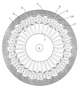
Figure 1, where the system is viewed with the top section of the engine
removed,
comprises the principal chamber 1 housed within the engine block 2. The engine
block 2
is seen as a continuous circular housing having an outer wall 3 and an inner
wall 4, both
substantially circular in cross section. The principal chamber 1 extends
uninterrupted
throughout the entire circular housing and consists of a specific pattern of
expanded and
restricted portions that repeats itself throughout the entire length of the
principal chamber
1. Housed within principal chamber 1 is a ring of interconnected traveling
cylinders 5.
The ring of traveling cylinders transmits rotary motion to the driveshaft 6
through a
plurality of drive spokes 7. Also illustrated in Figure 1 is a secondary
chamber 8 which
accommodates the outer wheels 9 of the pistons 10 contained within the
traveling
cylinders 5.
As illustrated in cross-section in Figure 2, the principal chamber l and the
secondary chamber 8 are formed from a circular top section 11 bolted onto a
circular
lower section 12 with the central hub portion of the sections 13 securing the
driveshaft 6
and the distal ends of the sections meeting at a common point 14. The two
sections 11, 12
further define a crankcase cavity 15 which houses the drive spokes 7. A
continuous slit
16 is seen cut into the inner wall of the principal chamber. The continuous
slit 16 is
required to accommodate the width of the drive spokes 7, so they may penetrate
the
principal chamber 1, and the connecting rods 17 (see Figure 1) that attach the
wheels 9 to
the pistons 10, so they may penetrate the crankcase cavity. A secondary
continuous slit
18 is cut into the outer wall of the principal chamber 1. This slit allows the
outer
9
CA 02366360 2001-09-20
WO 00/57044 PCT/US00/07743
connecting rods 17 (see Figure 1 ) to penetrate the secondary chamber 8 to
attach to their
respective wheels 9.
In Figure 3 there is illustrated in isolated view the end portion of the upper
section
11 firmly secured to the end portion of the lower section 12 by a number of
bolts 19. In
this particular arrangement, it should be noted that rather than having a flat
connection 14,
there is provided a series of interlocking teeth 20, which allow the upper and
lower
sections 11, 12 to be more easily aligned and to engage more securely to one
another.
Although not visible in this figure, there are also teeth, perpendicular to
the teeth shown,
that radiate from the center of the engine. Once again, there is seen clearly
the principal
to chamber 1 with the continuous slit 16 in its inner wall and the secondary
continuous slit
18 in its outer wall. Also seen is the secondary chamber 8 that accommodates
the outer
wheels 9 of the connecting rods 17. Seen in greater detail than in the
previous figures is a
pair of opposing pistons 10 housed within a traveling cylinder 5. Each of the
pistons has
a connecting rod 17, each of which holds two pairs of wheels 9. The outer
pairs of
wheels are responsible for separating the pistons 10 during the induction
cycle and the
occasional misfire while the inner pairs of wheels move the pistons together
during the
compression and exhaust cycles. Also seen in Figure 3 are two ports 21 one cut
through
the ceiling and another cut through the floor of the principal chamber. During
the
induction cycle, the two ports 21 line up with the port interfaces 22 which
are cut through
2o the top and bottom sides of the cylinder 5, to allow fresh air to be
admitted into the
cylinder.
In Figure 4 a portion of the principal chamber 1 is viewed with all of the
moving
components of the engine removed. As stated earlier, the contoured walls of
the principal
chamber 1 form a pattern of expanded and restricted areas that is repeated
throughout the
entire length of the principal chamber 1. Returning to Figure 4, a plurality
of ports 21, 24
and fuel injectors 23 are seen in the floor of the principal chamber 1. First,
there is seen
an intake port 21, soon followed by a fuel injector 23, and finally an exhaust
port 24.
This pattern of port 21 fuel injector 23 port 24 is repeated throughout the
entire length of
the principal chamber 1. Although not visible in this illustration, intake
ports 21, fuel
injectors 23 and exhaust ports 24 are also found in the ceiling of the
principal chamber 1
in the same positions as shown on the floor, (see Figures 3 and 8).
Figure 5 illustrates a cross-section view of a series of traveling cylinders 5
moving
through the expanded and restricted areas of the principal chamber 1. Also
illustrated are
CA 02366360 2001-09-20
WO 00/57044 PCT/US00/07743
the partial features of two inlet ports 21, a fuel injector 23, and two
exhaust ports 24 as
they relate to the various cylinders 5 within the system.
For a full understanding of the main operational concept of the Inverse
Peristaltic
Engine, reference is given to Figures 6A through 6J where a single isolated
traveling
cylinder is illustrated as it passes through the cycles of induction,
compression,
combustion and exhaust. Although they would not normally be visible in this
particular
type of cross-section view, the port interfaces have been included in order to
illustrate
their positions in relation to the various ports and fuel injectors. While
these figures
depict only a single traveling cylinder, it should be understood that each
cylinder within
the system is constantly undergoing these same processes pursuant to its own
timetable.
In Figure 6A, an isolated traveling cylinder 5 is depicted within one of the
narrow
necks of the principal chamber 1. At the cylinder's present position, the
pistons 10 have
come together fully, and the port interface 22 is just over front end of an
intake port 21.
In 6B, the cylinder 5 has left the narrow neck of the principal chamber 1 and
is
completely over the intake port 21. As the pistons 10 separate, they form a
vacuum
within the cylinder 5, which draws in fresh air through the intake port 21. In
6C, the
cylinder 5 has entered a wide neck in the principal chamber 1 and the pistons
10 have
fully separated and completely filled the cylinder 5 with fresh air. (Notice
that the inner
and outer walls of the wide neck of the principal chamber 1 are of sufficient
length so that
the port interface 22 may fully clear the intake port 21 before the cylinder 5
begins its
compression cycle.) In 6D, the cylinder 5 is entering a narrow neck of the
principal
chamber 1, forcing the pistons 10 together and hence compressing the air. In
6E, the
cylinder 5 has completely entered the narrow neck of the principal chamber l
and fully
compressed the air. At this point the port interface 22 is lined up with the
second fuel
injector 23. The fuel injector 23 will now inject a fine mist of diesel fuel
which will
ignite upon contact with the hot, compressed air, thus commencing the
combustion cycle.
(The first fuel injector 23 is only used when the engine is run at high RPMs
and there is
less time to inject fuel into the cylinders 5. Under these circumstances, the
first fuel
injector 23 switches on to work in unison with the second injector 23 in order
to provide
the additional injection time needed to deliver the proper amount of fuel.) In
6F, the
expanding gases push the pistons 10 apart, forcing the cylinder 5 to roll into
a wide neck
of the principal chamber 1. In 6G, the cylinder 5 has traveled into the wide
neck of the
principal chamber 1, thus ending the combustion cycle. (Notice that the
exhaust port 24
CA 02366360 2001-09-20
WO 00/57044 PCT/US00/07743
has been placed where it will not interfere with sealing during the combustion
process.)
In 6H, the port interface 22 is over an exhaust port 24 and the pistons are
being forced
together as the cylinder travels into a narrow neck of the principal chamber
1. As the
pistons 10 approach one another, they create a high pressure within the
cylinder 5, which
expels the exhaust fumes left over from the combustion cycle. In 6I, the
cylinder 5 has
fully exhausted and is now in the narrow neck of the principal chamber 1.
(Notice that
the exhaust port 24 and intake port 21 are appropriately distanced to allow
the optimal
level of port overlap suited for the demands placed on the system.) In 6J, the
cylinder 5 is
over a second intake port 21. Once again, the cylinder 5 will refuel as it
enters another
1 o wide neck of the principal chamber l and begins to repeat the cycles.
Reference is now given to Figure 7 where a series of traveling cylinders 5 is
illustrated moving through the expanded and restricted areas of the principal
chamber 1
with the drive spokes 7 passing through the continuous slit 16 in the
principal chamber's
inner wall. Surrounding the port interfaces 22 is a pair of concentric, square
interface
seals 25. The interface seals 25 seal the port interfaces 22 from the
surrounding
atmosphere during the engine's compression and combustion cycles. The square
shape of
the interface seals allows each of the seals' four sides to wear evenly and
causes the seals
to wear an even trench into the ceiling and floor of the principal chamber 1.
These
elements combined ensure that the interface seals 25 maintain good, level
contact with the
2o ceiling and floor of the principal chamber 1 over a long period of time.
The square shape
of the interface seals 25 also allows the engine to have the ability to
function equally
while rotating clockwise or counterclockwise. Surrounding the interface seals
25 are the
oil seals 26. The oil seals 26 prevent any lubricating fluids that may be
present within the
principal chamber 1 from seeping into the intake and exhaust ports 21,24 by
keeping the
area on the ceiling and floor of the principal chamber that surrounds the
ports 21,24 free
from oil. Because the interface seals 25, which need lubrication to promote
good sealing
and to prevent premature wear, fall within this area, either an oil roller 27
or a high
density cloth wick is placed before each pair of interface seals to provide
the needed
lubrication. A thick coating of oil in this area would defeat the purpose of
the oil seals
26, so the oil rollers 27 function on the same concept as that of a ball point
pen, rolling a
thin coating of oil over the contacting surfaces on the ceiling and floor of
principal
chamber 1 without dripping oil into the ports 21,24. If wicks are used in
place of rollers,
they will be kept slightly damp so that they too may only apply a thin coating
of oil. Also
12
CA 02366360 2001-09-20
WO 00/57044 PCT/US00/07743
found in the area between the oil seals 26 are four scrapers 28. The scrapers
28 even out
the wear area just off the inner and outer tips of the smaller interface seals
25. At this
point the wear areas of the smaller and larger interface seals 25 do not
overlap, so
additional wear is necessary to maintain a single level wear trench.
Additionally, the
angle and placement of the oil seals 26 are such that their wear areas on the
surface of the
principal chamber 1 will be of equal depth and will be contiguous to the wear
areas of the
interface seals 25, again maintaining a single level wear trench. It also
should be noted
that the length of the oil rollers 27 matches the width of the wear trench, so
that over time,
the rollers 27 will remain in good contact with the wear prone areas.
to To further illustrate the position of the fuel injectors 23, reference is
given to
Figure 8 where there is seen an end view of the upper and lower sections 11,
12 forming
the principal chamber 1 with the continuous slit 16 in its inner wall and the
secondary
continuous slit 18 in its outer wall. Also seen is the secondary chamber 8
that
accommodates the outer wheels 9 of the various connecting rods 17. In this
particular
view, there are two fuel injectors 23, one in the upper section 11 and the
other in the
lower section 12. It should be noted that the fuel injectors 23 are flat-faced
so that they
do not extend into the principal chamber 1. The various seals 25,26 can also
be seen here
pressed against the ceiling and floor of the principal chamber 1 by small
springs
concealed beneath them. The seals 25,26 and the scrapers 28 are similar in
construction
2o to piston rings in that they fit into recessed grooves cut into the top and
bottom of the ring
of traveling cylinders 5.
Figure 9 illustrates two metal plates 28 recessed into the block of the
engine. The
two plates 28 consist of a metal infused with dry lubricants to allow the oil
rollers 27 or
wicks, previously depicted in Figure 7, to be eliminated. By threading the
holes in the
plates that the ends of the fuel injectors 23 pass through, it is possible to
use the fuel
injectors 23 to secure the plates 28 to the block.
Figure 10 is an X-ray view of the oil galleries 30 that carry high-pressure
oil to the
various moving components of the engine. The oil galleries 30 originate in the
driveshaft
6 and travel through the drive spokes 7 to connect with the four main
galleries 31 in the
3o ring of cylinders 5. From here the galleries 30 branch off to bring
lubrication to where it
is needed within the engine.
Figures 11 A and 11 B illustrate the pistons 10 with a sliding groove 32 that
connects the oil galleries 30 within the pistons 10 and connecting rods 17 to
the main
13
CA 02366360 2001-09-20
WO 00/57044 PCT/US00/07743
galleries 31 within the ring of cylinders. As can be seen through a comparison
of Figure
11A and Figure 11B, the length of the groove 32 allows this connection to be
maintained
regardless of the pistons' 10 position the within the cylinders 5 to provide
continuous
lubrication for the pistons 10 and wheels 9.
Figure 12 illustrates how intake flow and swirling can be maximized by
offsetting
the ports 21,24 and port interfaces 22 to create a vortex within the cylinders
5 during the
intake and combustion cycles. During the intake cycle, the vortex formed
within the
cylinders 5 minimizes turbulence, therefore reducing intake resistance and
allowing a
larger volume of air to be admitted into the cylinders 5 during the allotted
intake time. In
to the combustion cycle, the swirling effect of the vortex produced during the
early stages of
combustion promotes good mixing of the fuel and air and circulates the flame
to ensure a
clean and complete burn.
In Figure 13 a ridge 33 protrudes from the ceiling and floor of the principal
chamber 1 to slide within a trench 34 cut into the top and bottom of the ring
of cylinders
5. This configuration minimizes the depth of the port interfaces 22 without
reducing the
thickness of the walls of the cylinders 5, thus allowing for a higher
compression ratio
without sacrificing the integrity of the ring of cylinders 5.
Figures 14 and 15 illustrate methods of preventing the various pistons 10 from
attempting to rotate on their axes. In figure 14, the primary and secondary
continuous
2o slits 16,18 have been narrowed and the connecting rods 17 have been fitted
with a flat
area 35. The flat areas 35 slide securely within the continuous slits 16,18,
preventing the
pistons 10 from attempting to rotate. In figure 15 a pair of fins 36 has been
included on
each of the pistons 10. These fms 36 slide within a pair of grooves 37 cut
into the inner
walls of the cylinders 5, again preventing the pistons 10 from attempting to
rotate.
Rotation of the pistons is highly unlikely to pose a problem in the Inverse
Peristaltic Engine for two reasons: the first is that there is no measurable
force that
motivates them to do so and the second is that the only times that rotation of
the pistons is
physically possible is when the wheels on the connecting rods pass through
areas of the
principal chamber where the inner and outer walls have no slope. These areas
of no slope
occur only at the peaks and valleys of the peristaltic pattern and span such a
minute
distance that, in most cases, the wheels on the connecting rods will be too
large to contact
them exclusively. Bearing this in mind, it should be reasonable to assume that
in a
normal peristaltic configuration no course of action will be necessary to
prevent the
14
CA 02366360 2001-09-20
WO 00/57044 PCT/US00/07743
pistons from rotating.
Figure 16 illustrates a second embodiment of the present invention that
eliminates
the need for drive spokes 7 through the utilization of a pair of large conic
gears 38
engaged to a toothed surface 39 on the ring of traveling cylinders 5. In
exchange for
torque, this configuration significantly increases both the RPM output of the
engine and
the structural integrity of the principal chamber 1.
Figure 17 illustrates a third embodiment of the engine that nearly eliminates
all
friction and wear within the cylinders 5 by eliminating the horizontal force
exerted on the
to cylinders' S interior walls. In this embodiment, the ring of cylinders 5
includes
protrusions 40 that penetrate the inner and outer continuous slits 16,18 to
receive the
horizontal force directly from the connecting rods 17. Each of the protrusions
40 holds
two wheels 41 which grip the sides of the connecting rods 17 and roll back and
fourth as
the connecting rods 17 reciprocate with the pistons. In addition to
eliminating wear
within the cylinders 5, this embodiment also allows shorter pistons 10 to be
used within
the engine, thus significantly reducing the engine's reciprocating mass.
Although not
illustrated in Figure 17, the attachment between the pistons 10 and connecting
rods 17
may be hinged to ensure that any imprecision where the wheels 41 of the
protrusions 40
grip the connecting rods 17 does not translate into a minor horizontal force
still being
2o transferred to the walls of the cylinders 5.
When short pistons 10 are used in the third embodiment of the engine, it
becomes
difficult to supply oil to the wheels 9 on the connecting rods 18 using the
original method
of lubrication (see Figures 11 A and 11 B). Figure 18 illustrates a hinged oil
tube 42 that
bridges the gap between the protrusions 40 on the ring of cylinders 5 and the
connecting
rods to deliver high-pressure oil directly to the oil galleries 30 within the
connecting rods
17 which lubricate the wheels 9. The oil tubes 42 receive their oil supply
from oil
galleries that branch off from the main galleries 31 that run within the ring
of cylinders S
(see Figures 10, 1 lA and 11B). While this method of lubrication is quite
unconventional,
the length of the oil tubes 42 is such that they need pivot only slightly as
they reciprocate
3o with the connecting rods 17, thus reducing any wear in their joints to an
absolute
minimum and ensuring exceptional reliability. If deemed more desirable, it is
also
possible to use a flexible hose in place of the hinged tube shown 42.
Figure 19 illustrates a fourth embodiment of the engine which also decreases
CA 02366360 2001-09-20
WO 00/57044 PCT/US00/07743
friction and wear within the cylinders 5. In this embodiment, the horizontal
force is
received by a pair of bars 43 attached to the connecting rods 17. The bars 43
connect the
connecting rods 17 to a plate 44 at the end of the drive spoke 7. The
connections 45
between the connecting rods 17 and the bars 43 and the bars 43 and the plate
44 are
hinged in order to compensate for the vertical travel of the pistons 10. Due
to the fact that
the cylinders 5 are no longer linked together, much of the system's original
stability has
been lost. To compensate for this lack of stability, a pair of tracks 46 has
been included
in the ceiling and floor of the principal 1 chamber and a pair of extensions
47 has been
included on the top and bottom of the cylinder 5 and the top and bottom of the
plate 44 at
1 o the end of the drive spoke 7. The extensions 47 slide within the tracks 46
as the linkage
travels through the principal chamber 1 to keep the cylinder 5 properly
aligned and give
additional support to the drive spoke 7.
Figure 20 illustrates a fifth embodiment of the engine. The fifth embodiment
operates under the same general theory as the previous embodiments; however,
in this
configuration the ring of cylinders 5 remains fixed while the principal
chamber 1 rotates.
To allow the principal chamber 1 to rotate, a primary block 48 has been
designed to
encompass and support the preexisting block 2, which, being the frame of the
principal
chamber 1, must now have the ability to rotate. In addition, the drive spokes
have been
removed from the ring of cylinders 5 and attached to the block 2, and, because
the
2o cylinders 5 are no longer traveling, the ports 21,24 have been replaced
with a more
conventional valve setup. The valves 49,50 are actuated by a contoured wall
51, similar
to the contoured walls of the principal chamber 1, that extends from the
traveling block 2
of the engine. This valve setup also includes a rocker 52 and a modified
pushrod 53 fitted
with a wheel 54. As the wheel 54 rolls over the peaks and valleys of the
contoured wall
51, the pushrod 53 tips the rocker 52, which in turn actuates the valve 49.
Although
efficient and durable, this method of controlling the various valves 49,50
could easily be
substituted with a valve setup similar to that used in radial aircraft
engines.
To further enunciate the properties of the preceding embodiment, Figure 21
illustrates a cross-section view of a portion of the fixed ring of cylinders 5
wherein there
3o is depicted an intake valve 49, a fuel injector 23 and an exhaust valve 50.
Because this
engine utilizes opposing pistons 10, the valves 49,50 and fuel injectors 23
are placed on
the side of the cylinders 5.
Figure 22 depicts the primary section of the Inverse Peristaltic Engine's
cooling
16
CA 02366360 2001-09-20
WO 00/57044 PCT/US00/07743
system. Illustrated is an end view of a number of air passages 55 cut through
the ring of
traveling cylinders 5. In this embodiment several holes are drilled into the
outer wall of
the secondary chamber 8 and the crankcase cavity 15 is vented by a high power
fan.
When the fan is activated, it forms a vacuum within the crankcase 15 which
draws cool
air through the holes in the secondary chamber 8 and into the outer portion of
the
principal chamber 1. From here the air travels through the air passages 55 and
in the
process removes excess heat from the ring of cylinders 5. The hot air then
enters the
crankcase cavity 15 where it is blown out by the fan and routed through an
intercooler
before reentering the system. For fewer moving parts, it may be possible to
eliminate the
1 o fan apparatus entirely by modifying the rotating internal workings of the
engine to
function as a centrifugal blower. In this embodiment, air would enter at the
crankcase
and be drawn outward through the cooling system by centrifugal force.
In Figure 23, the embodiment of the Inverse Peristaltic Engine seen in Figure
16
has been further modified to function as a brushless, alternating current,
integrated
generator/engine unit in which the armature 56 remains stationary and the only
moving
parts are the internal workings of the engine. As with the embodiment in
Figure 16, the
crankcase cavity 15 and its contents have been removed; however, in Figure 23,
the
secondary chamber 8 has been enlarged to house the generator portion of the
unit. In the
generator portion of the unit, a number of magnets 57 can be seen suspended
between the
2o armatures 56 by extensions 58 attached to the ring of cylinders 5. (The
magnets have
been extended outward from the ring in order to attain higher linear
velocities.) In
addition to the enlarged secondary chamber 8, a non-conducting gasket 59 has
been
placed between the outer ends of the top and bottom sections 11,12 of the
engine to
prevent the possible formation of an electric current within the block.
According to the
layout presented in Figure 22, a unit containing sixty magnets 57 and sixty
armature pairs
56 (the armature shown in Figure 23 is one pair) would produce an alternating
current at a
frequency of sixty hertz with the engine running at one-hundred and twenty
RPMs. As
will soon be illustrated in Figures 24A-24D, the generator/engine unit can be
modified to
produce a direct current by reconfiguring the polarity of the magnets 57 and
rewiring the
3o armature 56. In addition, it may be possible to configure the magnets 57
and the block of
the engine so that the armature 56 may be placed externally. The
generator/engine unit
may also make use of a more conventional arrangement in which the magnets 57
remain
fixed to the block of the engine while the armature 56 rotates; however, this
arrangement
17
CA 02366360 2001-09-20
WO 00/57044 PCT/US00/07743
will require brushes to transmit power from the armature 56.
Figures 24A-24D illustrate four recommended armature 56 and magnet 57
arrangements to be used in the generator/engine unit.
Figure 24A illustrates the alternating current arrangement used in Figure 22.
In
this arrangement the polarity of the magnets 57 alternates from one magnet to
another.
Figure 24B illustrates a direct current arrangement in which all of the
magnets 57 have
the same polarity. Figure 24C illustrates a simplified alternating current
arrangement
while Figure 24D illustrates a simplified direct current arrangement.
Figure 25 illustrates a sixth embodiment of the engine. In this embodiment the
cylinders 5 are oriented parallel to the driveshaft 6 instead of perpendicular
to the
driveshaft as in the original embodiments of the engine. Seen in new
positions, shapes
and sizes are the ring of cylinders 5, the crankcase cavity 15, driveshaft 6
and drive
spokes 7, the two secondary chambers 8, the fuel injectors 23, ports 21,24 and
port
interfaces 22, with an exhaust manifold 60 referenced for the first time. In
this cylinder
configuration the diameter of the engine no longer affects the slope of the
peristaltic
walls, thus allowing the size of the engine to be drastically reduced. To
allow the engine
to be easily assembled, the connecting rod assembly 17 on each of the pistons
10 has been
adapted to carry only one pair of wheels 9 and the peristaltic walls,
hereinafter referred to
as the peristaltic track 61, have been modified accordingly.
2o To further emphasize the size reduction capabilities of the parallel
cylinder
configuration, the engine in Figure 26 has been constructed at an ideal scale
to hold one
four-stroke peristaltic pattern repeat. This engine, as well as those depicted
in the
following figures, will function best with four to seven cylinders 5,
depending on the
diameter of the engine.
The Engine in Figure 26 can be further reduced in size by configuring it to
function as a two cycle engine; however, this is somewhat undesirable because
a two-
cycle pattern robs the peristaltic configuration of much of its defining
flexibility that
allows the expansion or compression rate, stroke length, time duration and
compression
ratio of each the engine's four cycles to be fully adjustable and to vary from
one cycle to
3o another (See Efficiency). A two-cycle pattern could, however, be configured
with dwell
time to provide the engine with superior scavenging capabilities.
Seen in partial view in the preceding figure and clearly in the cross-section
view
in Figure 27, is an enlarged plenum area 62 in the throat of the intake and
exhaust ports
18
CA 02366360 2001-09-20
WO 00/57044 PCT/US00/07743
21,24. If the ports 21,24 were cut completely through the block for the entire
span of the
intake and exhaust strokes in an engine having only one four-stroke
peristaltic pattern
repeat, the integrity of the block would be severely compromised. The plenum
areas 62
allow the ports 21,24 to be cut only partially through the block for the
majority of the
span of the intake and exhaust strokes to preserve the strength of the block.
Also seen in
Figure 26 is a multitude of small holes 55 drilled through the ring of
cylinders 5. The
holes 55, which could also be substituted for slits, are derived from the
embodiment
depicted in Figure 22 and function as the primary section of the engine's
cooling system.
In the embodiment in Figure 26, cool air is first drawn into one of the
engines two
1o secondary chambers 8. From here the air proceeds to travel through the
holes 55 in the
ring of cylinders 5 where it removes excess heat from the cylinders 5 before
entering the
second secondary chamber 8 as hot air. The hot air is then drawn out of the
second
secondary chamber 8 by a high power fan and, as was done in Figure 22, routed
through
an intercooler before it reenters the system.
To eliminate the need for a fan assembly, the embodiment illustrated in Figure
28
includes air scoops 63 that extend over the drilled portions 55 of the ring of
cylinders 5.
As the ring of cylinders 5 rotates, the scoops 63 at the top portion of the
ring form a
positive pressure above the holes 55 while the scoops at the bottom of the
ring form a
negative pressure below the holes. This pressure difference forces air in the
top
2o secondary chamber 8 to pass through the holes 55 and to continue to
circulate through the
system.
Figure 29 illustrates the generator/engine unit, first introduced in Figure
23, as
applied to the parallel cylinder configuration.
Figure 30 illustrates an additional embodiment of the engine in which the
traditional opposing piston configuration has been reduced to one piston per
cylinder in
an attempt to both simplify and further reduce the size of the engine. In this
configuration
the ports 21,24 have been moved to the top of the engine where they interface
directly
with the open top ends of the cylinders 5. Because this engine does not have
opposing
pistons 10, an upward force is now exerted on the ring of cylinders 5. To
counteract any
3o negative effects of this force, a number of bearings 64 has been placed
between the ring
of cylinders 5 and the top inside wall of the engine to reduce friction
between the
contacting surfaces.
Because of the new port placement in the single piston per cylinder version of
the
19
CA 02366360 2001-09-20
WO 00/57044 PCT/US00/07743
engine, it was necessary to devise a new type of cooling system. Figures 31
and 32
illustrate the various features of this system, which utilizes oil as a
cooling fluid. In
Figure 32 the ring of cylinders 5 is seen isolated from the engine. Except for
two disc
sections, all of the portions of the ring that lie between the cylinders 5
have been
removed, leaving an open area surrounding the cylinders which, when placed
within the
block of the engine, serves as a reservoir 65 for the cooling oil. On the top
disk section of
the ring, four port interfaces 22 are seen positioned above their respective
cylinders 5. At
the center of the disk section there is seen a fifth hole 66, the purpose of
which, as will
soon be discussed in detail, is to introduce cooling oil to the reservoir area
65 between the
l0 cylinders 5. Now turning to Figure 31, there is seen a cross section of the
engine
illustrating three oil passages 67 cut through the block: one cut through the
top of the
block to allow oil to enter the reservoir and two cut through the side of the
block to allow
oil to exit. When the engine is activated, the cylinders 5 act as a vane and
cause the oil
that surrounds them to rotate with the ring of cylinders 5. As the oil's
rotational velocity
increases, centrifugal force creates a pressure difference between the inner
and outer
portions of the oil's rotating mass. This pressure difference draws cool oil
through the
hole 66 in the upper disk section of the ring of cylinders 5 and into the
reservoir 65.
Upon entering the reservoir 65, the oil flows outward, removing heat from the
cylinders 5
before eventually exiting as hot oil through the two passages 67 in the side
of the block.
2o The hot oil then passes through a radiator 68 where it is cooled before
reentering the
system. Although oil provides a more thorough heat exchange, this system may
also be
adapted to use air as a cooling fluid.
Figure 33 illustrates a third generator/engine unit as applied to the single
piston
per cylinder configuration of the engine.
Figure 34 illustrates the most preferable of three cooling systems adapted for
the
single piston per cylinder generator/engine unit. In Figure 34, the ring of
cylinders 5
includes reservoir areas 65 between each of its cylinders, which, as in
Figures 31 and 32,
are supplied with a continuous flow of cool oil. In addition, the block of the
engine has
been modified to include two annular groves 69 that form a continuous
interface with the
reservoir openings 70 to allow cooling oil to enter and exit each reservoir
65. As the
engine/generator unit begins to rotate, centrifugal force creates a pressure
difference
between the inner and outer reservoir openings 70. This pressure difference
draws cool
oil from the inner annular grove 69 into the top portion of the reservoirs 65.
Upon
CA 02366360 2001-09-20
WO 00/57044 PCT/US00/07743
entrance, the oil commences to flow down through the reservoirs 65, removing
heat from
the cylinders 5 before exiting into the outer annular 69 grove as hot oil.
From the outer
annular grove, the hot oil then passes through one of two galleries 71 and one
of two
radiators 68 before eventually returning to the reservoirs 65 as cool oil.
Figure 35 illustrates the second most preferable cooling system for the single
piston per cylinder version of the generator/engine unit. This cooling system
operates
under the same concept as the previous air-cooled systems; however, in this
system air
must enter from the side of the ring of cylinders 5 so as not to interfere
with the port areas
at the top of the engine. As in the previous air-cooled systems, cool air is
drawn through
to holes or slits 55 in the areas between the cylinders to remove excess heat
from the engine
(refer to Figures 21 and 26 and their respective text). Figure 35 also
illustrates, for the
first time in this application, the fan 72 and the intercooler 73.
The third cooling system for the single piston per cylinder version of the
generator/engine unit is illustrated in Figure 36. Similar to the system
introduced in
Figure 34, this cooling system also uses oil as a cooling fluid, however, it
does not make
use of centrifugal force. Instead it uses a high volume oil pump (not shown)
to circulate
oil through the system. Although the requirement for an oil pump is not
desirable, this
system will be advantageous under extreme operating conditions because oil
exiting the
reservoirs 65 is directed to provide supplementary lubrication to the
peristaltic track 61.
2o Figure 37 illustrates an additional embodiment of the engine in which the
cylinders 5 remain stationary. In some applications where the engine is
required to make
sudden extreme changes in running speed, it will be desirable to have a low
flyweight. In
the embodiment in Figure 37 the peristaltic track 61 has been replaced with a
peristaltic
plate 74 which rotates with the driveshaft 6 while the cylinders 5 remain
stationary. This
configuration eliminates the ring of cylinders 5 which was responsible for the
majority of
the previous engines' rotational inertia. Although the engine now utilizes
stationary
combustion chambers, the simplicity, reliability and superior aspiration of a
port system
were able to be salvaged through the use of a port distributor disk 75. The
port distributor
disk 75 is attached directly to the top of the driveshaft 6 and has slits or
port bridges 76
that connect the intake and exhaust ports 21, 24 to the cylinders 5 during the
appropriate
cycles. In order to properly time the intake and exhaust cycles, the port
bridges 76 travel
directly above the intake and exhaust stroke portions of the peristaltic plate
74. In Figure
37 the port bridge 76 is seen connecting the engine's right cylinder 5 to its
respective
21
CA 02366360 2001-09-20
WO 00/57044 PCT/US00/07743
exhaust port 24 while the left cylinder 5 remains blocked off. Without a
traveling ring of
cylinders 5, the cylinders 5 can no longer share common ports 21,24, so in
this
embodiment each cylinder 5 has its own intake and exhaust ports 21,24. Figures
38A and
38B together illustrate a top and bottom view of the port distributor disk 75.
38A is a top
view of the disk 75, illustrating the portions of the intake 77 and exhaust
bridges 76 that
interface with the ports 21,24, while 38B is a bottom view of the disk 75,
illustrating the
portions of the intake 77 and exhaust 76 bridges that interface with the
cylinders 5.
Figures 39A-39D illustrate the changing positions of the port distributor disk
75 as
to the two cylinders 5 in view pass through four cycles. Each new figure
represents one
quarter turn of the driveshaft 6.
Reference is now given to Figure 39A. At this moment the port distributor disk
75 has connected the left cylinder 5 to its respective exhaust port 24,
allowing it to
exhaust while the right cylinder 5 remains blocked off during its compression
cycle.
Advancing one-quarter turn to Figure 39B, the port distributor disk 75 has now
connected
the left cylinder 5 to its respective intake port 21 during its intake cycle
while the right
cylinder 5 remains sealed during its combustion cycle. Advancing an additional
quarter
turn to Figure 39C, the left cylinder 5 is seen blocked off during its
compression cycle
while the right cylinder 5 is seen connected to its exhaust port 24 during its
exhaust cycle.
2o Finally, after having advanced a total of three-quarter turns, Figure 39D
illustrates the left
cylinder 5 sealed off during its combustion cycle while the right cylinder 5
is seen
connected to its respective intake port 21 during its intake cycle.
One of the advantages of the port distributor disk 75 is that it can be
modified to
allow variable port timing. Figures 40A and 40B illustrate top and bottom
views of a port
distributor disk 75 that consist of three concentric sections. By using
control devices
similar to those found in the variable valve timing systems of conventional
engines, the
three sections of the port distributor disk 75 can be slightly rotated in
relation to one
another to vary the intake and exhaust timing according to the RPMs of the
engine.
Even without variable port timing, the aspiration of the Inverse Peristaltic
Engine
3o is far superior to valve fed systems. However, with the engine's myriad
possible
applications, this feature may be deemed valuable under certain operating
conditions.
Although the embodiments illustrated in figures 37-39-D use a port distributor
disk 75 to control intake and exhaust, an engine using the peristaltic plate
74
22
CA 02366360 2001-09-20
WO 00/57044 PCT/US00/07743
configuration that was illustrated in these figures would also function
extremely well
using a conventional valve setup.
Figure 41 illustrates an additional embodiment of the engine in which the
connecting rods 17 are fitted with conic wheels 9 to reduce cornering wear. In
the all of
the vertical cylinder configurations of the engine, particularly those with
small radii, the
outer edges of the wheels 9 are forced to cover more distance than the inner
edges that are
closer to the center of the engine. Over time, this effect may eventually
cause
unnecessary wear to the wheels 9 and the peristaltic track 61. By allowing the
wheels 9
to be conic according to the radius of the engine and by modifying the surface
of the
peristaltic track 61 to fit their new shape, this wear can be eliminated.
Figures 42-48B illustrate different types of open engine cooling systems. Open
engine cooling systems, which are the simplest and most efficient cooling
systems for use
in the Inverse Peristaltic Engine, do not draw cooling air through the
crankcase, so they
can remain directly open to the atmosphere without discharging oil vapors.
Although
Figures 42-48B only illustrate the systems as applied to the single piston per
cylinder
version of the engine, the single piston per cylinder version of the
generator/engine unit,
and the original perpendicular cylinder version of the engine, the open engine
family of
cooling systems may be effectively adapted to all versions of the engine and
generator/engine units.
2o The open engine cooling system illustrated in Figure 42 was derived from
the oil-
cooled system depicted in Figures 31 and 32. Except for two disc sections, all
of the
portions of the ring of cylinders 5 that lie between the cylinders 5 have been
removed,
leaving an open area 78 surrounding the cylinders 5 (see Figure 32). In
addition, two
large passages 79 have been cut through opposite sides of the block. Within
one of the
passages 79 resides a fan 80. When the fan 80 is activated it continuously
draws cool air
through the opposing passage 79 and into the open area 78 surrounding the
cylinders 5.
As the cool air flows around the cylinders 5, it removes excess heat from the
engine
before exiting as hot air through the passage 79 containing the fan 80.
Figures 43 and 44A-44C illustrate an open engine cooling system that
eliminates
3o the need for an exterior fan 80. In Figures 44A and 44B the ring of
cylinders 5 is seen
removed from the engine. On the top disk section of the ring, four port
interfaces 22 are
seen positioned above their respective cylinders 5. At the center of the disk
section there
is seen a fifth hole 81 which allows cool air to enter the open area 78
surrounding the
23
CA 02366360 2001-09-20
WO 00/57044 PCT/US00/07743
cylinders 5. Also seen is a number of fins 82 attached to the outer portions
of and
suspended between the four cylinders 5. These fins 82 may be arranged in the
standard
centrifugal pattern illustrated in Figures 44A and 44B or in the squirrel-cage
pattern
illustrated in Figure 44C. Now turning to Figure 43, there is seen a cross-
section view of
the engine revealing two passages 83,84 cut through the block: one passage 83
cut
through the top of the block to allow cool air to enter the system and one
passage 84 cut
through the side of the block to allow hot air to exit. Seen again are the
fins 82 that are
attached to the ring of cylinders. When the engine is activated the fins 82
act as a vane
and cause the air that surrounds them to rotate with the ring of cylinders. As
the air's
rotational velocity increases, centrifugal force creates a pressure difference
between the
inner and outer portions of the air's rotating mass. This pressure difference
draws cool air
through the hole 81 in the upper disk section of the ring of cylinders 5 and
into the open
area 78 surrounding the cylinders. Upon entering the open area 78, the cool
air flows
outward, removing heat from the cylinders 5 before exiting as hot air through
the passage
84 in the side of the block. Also illustrated in Figure 43 is a baffle plate
85 positioned
above the engine. The baffle plate 85 aids in the removal of excess heat from
the head
area of the engine by directing the incoming air flow over the top portion of
the block.
Figures 45 and 46 illustrate a single piston per cylinder version
generator/engine
unit utilizing an open engine cooling system that cools both the engine and
generator
2o portions of unit. The ring of cylinders S in this embodiment of the
generator/engine unit
is similar in construction to that of the engine discussed in the preceding
paragraph in that
all of the areas of the ring of cylinders 5 that lie between the cylinders 5
have been
removed, again, leaving an open area 78 surrounding the cylinders 5. However,
the ring
of cylinders 5 in this generator/engine unit does not have a driveshaft 6, so
a hole 81 has
also been cut through the center of the bottom disk section of the ring to
allow additional
cooling air to be admitted to the system. Generator/engine units using open
engine
cooling systems may use fans 80 as illustrated in Figure 45 or fins 82 as
illustrated in
Figure 46 to actuate the flow of air through the system. In both cases four
passages
83,86,87 have been cut through the block: one passage 83 cut through the top
section of
the engine portion of the unit and one passage 86 cut through the bottom
section of the
engine portion of the unit to allow cool air to enter the system, and two
passages 87 (this
number may be increased if necessary) cut through opposing lower sections of
the
generator portion of the unit to allow hot air to exit the system. The exit
passages 87 are
24
CA 02366360 2001-09-20
WO 00/57044 PCT/US00/07743
placed at the outer ends of the generator/engine unit so that the armature 56
in the
generator portion may be cooled in addition to the cylinders 5 in the engine
portion. This
generator/engine unit also includes a baffle plate 85 to assist in cooling the
head area of
the engine portion of the unit.
Figures 47 and 48A-48B illustrate an open engine cooling system being used in
the original perpendicular cylinder version of the engine. As with the
previous open
engine cooling systems, all of the portions of the ring of cylinders 5 that
lie between the
cylinders 5 have been removed to leave an open area 78 surrounding the
cylinders 5. In
Figure 47, several vents 88 are seen cut through the outer portion of the top
section of the
1o block. These vents 88, which are also cut through the bottom section of the
block, allow
air to pass through the cooling system. Now turning to Figures 48A and 48B
there is seen
a top and side view of a section of the ring of cylinders 5. All of the
portions of the ring
of cylinders 5 that lie between the cylinders 5 have been removed except for
an inner ring
section, a port interface 22 section and an outer ring section. Between each
of the
cylinders 5 there is seen a pair of fins 82. As the ring of cylinders 5
travels from left to
right, the fins 82 at the top of the ring form a positive pressure above the
open areas 78
surrounding the cylinders 5 while the fins 82 at the bottom ring form a
negative pressure
below the open areas 78 surrounding the cylinders 5. The difference in
pressure causes
cool outside air to flow in through the vents 88 in the top portion of the
block (see Figure
47), down through the open areas 78 surrounding the cylinders 5, and out
through the
vents 88 in the lower portion of the block. As the cool air continuously flows
over the
cylinders 5, it removes excess heat from the engine.
Figure 49 illustrates an annular collector channel 89, cut into the head area
of the
block of the engine, which captures and re-burns any blow-by gasses that may
manage to
escape the interface or port area seals (port area seals apply mainly to
turbocharged
engines). When and if blow-by gasses enter the collector channel 89, they are
immediately drawn back into the engine through a smaller channel 90 that
connects the
collector channel 89 to the intake area of the head. This allows the gases to
be properly
processed by the engine and vented through the exhaust system.
Normally aspirated Inverse Peristaltic Engines should not require a collector
channel, nor should Turbo-Diesel Inverse Peristaltic Engines. (In Turbo-Diesel
engines,
any leakage will only be compressed air, which is not harmful to the
environment.) The
collector channel will be most useful in turbocharged natural gas engines or
any other
CA 02366360 2001-09-20
WO 00/57044 PCT/US00/07743
turbocharged engines where high manifold pressures may cause small amounts air-
fuel
mixture to breach the port area seals.
In Figures 50 and 51 the engine has been modified to function as an integrated
centrifugal pump/engine unit. Integrated centrifugal pump units were derived
from and
function on the same principle as the open engine cooling system presented in
Figures 43
and 44A-44C. The only difference is that the units now pump fluids instead of
circulating
air. To allow the pump/engine units to handle fluids, flanges 91 were extended
from the
top and bottom sections of the ring of cylinders 5 to provide additional room
for seals. In
addition, two annular collector channels 92 were cut into the block near the
flange 91
to areas to capture and drain any pumping fluids that manage to breach the
seals. By
draining leakage from this area, the channels 92 prevent the pumping fluids
from
eventually seeping into the head and crankcase 15 areas of the engine. The
pump/engine
unit illustrated in Figure 50, which intakes pumping fluid through its top
section, has
retained its driveshaft 6, allowing it to function simultaneously as a
stationary engine and
drive other equipment as it is pumping fluids.
In Figure 51, the pump/engine unit illustrated has been fitted with a modified
driveshaft 6 that functions as a directly submersible intake and eliminates
the need for a
sealed intake area.
Centrifugal pump/engine units do not need cooling systems because the fluid
that
2o they are pumping serves as the engine's coolant. When large volumes are
being pumped,
the fluid will be only minimally heated by the engine. However, when it is
desirable for
the pumping fluid to be heated, lower volumes may be pumped and/or two or more
engines may be placed in series to eliminate the need to heat the fluid
elsewhere.
Figure 52 illustrates a generator/engine unit that has retained its driveshaft
6 so
that it may simultaneously serve as a stationary engine and drive other
equipment as it
generates electricity.
Figure 53 illustrates a single piston per cylinder version of the engine with
a
modified bearing 64 arrangement that may be advantageous for certain
applications.
Figure 54 illustrates a modified version of the oil-cooled embodiment of the
3o engine, previously depicted in Figures 31 and 32, that includes a
centrifugal filler tube 93
and an air displacer tube 94 which together ensure that the reservoir area 65
remains filled
with oil. In this embodiment, galleries 30 have been drilled through the
driveshaft 6 to
connect the filler tube 93 to the oil-filled crankcase cavity 15 and a passage
95 has been
26
CA 02366360 2001-09-20
WO 00/57044 PCT/US00/07743
cut though the block to connect the air displacer tube 94 to the crankcase
cavity 15. As
the engine rotates, centrifugal force causes the filler tube 93 to draw oil
from the
crankcase 15 until the reservoir areas 65 are filled. To allow the reservoirs
areas to 65
fill, the air displacer tube 94 provides a means for air that is displaced by
the incoming oil
to pass from the cooling system to the crankcase cavity 15. While less
desirable, it is also
possible to use a low-pressure oil pump in place of the galleries 30 and the
oil filler tube
93 to maintain the proper oil level within the reservoir area 65.
Figure 55 illustrates a single piston per cylinder version of the engine in
which a
to number of hydraulic lifters 95 raise and lower the peristaltic track 61 to
continuously vary
the overall compression ratio of the engine. In this embodiment, the
peristaltic track 61
has been manufactured with a number of radiating extensions 96 which slide
within a
number of tracks 97 cut into the inner wall of the block. The extensions 96
and the tracks
97 allow the peristaltic track 61 to be raised and lowered vertically by the
hydraulic lifters
95, but prevent the peristaltic track 61 from being rotated out of position by
the pistons
10. The hydraulic lifters 95 receive their commands from an electronic control
unit (not
shown) that takes into account a number of variables that may include the
engine's
workload, RPMs, temperature, manifold pressure, intake volume and exhaust gas
composition in order to maximize the engine's efficiency and emission quality
at any
given moment.
Figure 56 illustrates a second variable compression ratio embodiment of the
engine. In this embodiment, the height of the peristaltic track 61 is
controlled by a
number of worm drives 98 linked, synchronized, and driven by a chain 99. Power
is
provided to the chain 99 by one or more bi-directional electric motors 100 or
by a bi-
directional PTO (not shown), either of which, as with the lifters 95 in the
previous
embodiment, would be controlled by an electronic control unit. Seen also in
this
embodiment are the radiating extensions 96 and the tracks 97 cut into the
inner walls of
the block which work together to prevent horizontal rotation of the
peristaltic track 61
while still permitting its vertical travel.
3o A third type of variable compression ratio device is illustrated in Figure
57. In
this embodiment an annular screw drive mechanism is used to vary the height of
the
peristaltic track 61. The annular screw drive consists of a hollow, open-
ended, cylinder-
shaped male portion 101, inside of which the peristaltic track 61 is bolted,
and a smaller
27
CA 02366360 2001-09-20
WO 00/57044 PCT/US00/07743
ring-shaped female portion 102. The block of the engine is constructed in such
a way that
the female ring portion 102 of the screw is able to rotate horizontally about
the engine's
axis, while the male cylinder portion 101 includes extensions 96, which slide
within
tracks 97 cut into the inner walls of the block, to allow it and the
peristaltic track 61 to be
raised and lowered vertically, but prevent them from being rotated
horizontally. The
bottom of the male cylinder portion 101 includes protruding male screw threads
that fit
inside the female screw threads cut into the female ring portion 102. By
rotating the
female portion 102 in one direction or the other, the male portion 101 and the
peristaltic
track 61 can be raised or lowered accordingly. Although not illustrated in
this figure, a
to portion of the female ring section 102 is toothed so that it may be engaged
by a
hydraulically driven rack or a bi-directional, electric motor or PTO driven
worm drive, or
be directly geared to a PTO or electric motor. As with the two' preceding
embodiments,
whatever power input device is selected will be best controlled by an
electronic control
unit.
Figure 58 illustrates a fourth continuously variable compression ratio
embodiment
of the engine in which the lifting device consists of two cam rings 103,104.
The upper
cam ring 103 supports the peristaltic track 61 and includes extensions 96 that
slide within
tracks 97 cut into the inner wall of the block to prevent horizontal rotation,
while the
lower cam ring 104 is constructed so that it may be rotated on the engine's
axis. When
2o the lower cam ring 104 is rotated, it lifts the upper cam ring 103 and the
peristaltic track
61 and hence varies the engine's compression ratio. As with the preceding
figure, a
portion of the lower ring 104 is toothed so that it may be engaged by a
hydraulically
controlled rack or by an electric motor or PTO driven worm drive.
Figure 59 illustrates a hydraulically controlled continuously variable
compression
ratio device that may be ideal for extreme operating conditions or simply to
obviate the
need for a modified peristaltic track 61. In this embodiment of the engine the
peristaltic
track 61 is bolted within an open-ended, hollow cylinder 105. As with the
previous
embodiments, the cylinder 105 includes radiating extensions 96 which slide
within tracks
97 cut into inner walls of the block to allow the cylinder 105 and peristaltic
track 61 to be
3o raised and lowered vertically, but prevent them from being rotated
horizontally. The
cylinder 105 is raised and lowered by a number of hydraulic lifters 95, as in
Figure 55.
Figure 60 illustrates an opposing piston version of the engine with
continuously
variable compression ratio abilities. In this embodiment, the upper
peristaltic track 61 has
28
CA 02366360 2001-09-20
WO 00/57044 PCT/US00/07743
been bolted within an open ended, rotatable cylinder 106 so that it may be
rotated on the
engine's axis. A portion of the rotatable cylinder 106 has been toothed so it
may be
engaged by a hydraulically driven rack or a bi-directional electric motor or
PTO driven
worm drive. As the cylinder 106 and peristaltic track 61 are rotated, the
timing of the
upper group of pistons 10 changes in relation to the lower group of pistons 10
so that the
two groups no longer arrive at their Top Dead Center positions at the same
moment, thus
varying the engine's compression ratio. Although this method of providing
variable
compression ratio abilities to the opposing piston versions of the engine is
ideal, the
opposing piston versions of the engine may also vary the height of one or both
of their
1o peristaltic tracks 61 through the same means as one of the five preceding
embodiments.
Figure 61 illustrates a fixed cylinder embodiment of the engine (see Figures
37-
39D) that has been modified to incorporate a continuously variable compression
ratio
device. In this embodiment the driveshaft 6 includes a number of extensions 96
which
slide within a number of tracks 97 cut into the peristaltic plate 74 to allow
the height of
peristaltic plate 74 to be varied while it remains engaged to the driveshaft
6. The height
of the peristaltic plate 74 is regulated by a thrust bearing arrangement 107
that is coupled
to a number of worm drives 98. The power needed to raise and lower the plate
can be
provided to the system by a bi-directional electric motor 100 or a bi-
directional PTO,
either of which can be linked to the worm drives 98 by chain 99. It is also
possible to
2o substitute the worm drives 98 in this embodiment with hydraulic lifters 95
(see Figures 55
and 59).
Figure 62 illustrates an additional fixed cylinder embodiment of the engine
which
employs a simplified version of the variable compression ratio device
illustrated in the
previous figure. In this engine, the contacting surfaces 108 of the thrust
bearing 107 and
the hub portion 109 of the lower section of the block have been threaded so
that the thrust
bearing 107 and hub 109 may function as the nut and bolt sections of a worm
drive. As
the thrust bearing 107 is rotated one direction or the other, the peristaltic
plate 74 and the
compression ratio of the engine is raised or lowered. Although not illustrated
in this
figure, the outer edge of the thrust bearing 107 is toothed so that it may be
engaged by a
rack and be rotated hydraulically or be engaged by a worm drive and be rotated
electrically by a bi-directional motor. As with all of the previous
continuously variable
compression ratio devices, the power input device for this variable
compression ratio
system would be best controlled by an electronic control unit.
29
CA 02366360 2001-09-20
WO 00/57044 PCT/US00/07743
Figure 63 illustrates an embodiment of the engine in which spark plugs 110
travel
with the cylinders 5. Also seen in this figure are a condenser coil 111 and an
electrode
112 residing within a track 113. As the spark plugs 110 travel with the
cylinders 5, they
act as their own distributor and are individually fired as they pass the
electrode 112. The
ignition timing of the engine can be retarded or advanced by varying the
position of the
electrode 112 within its track 113 or by eliminating the track and widening
the electrode
to the length of the former track 113 and signaling the coil 111 to fire at
earlier or later
times and for longer or shorter intervals.
Figure 64 illustrates a porous ceramic plate 114 recessed into the head of the
1o engine which can be used in place of the oil rollers or wicks 27 depicted
earlier in this
application (see Figure 7). The porous ceramic plate 114 is connected to an
oil reservoir
or the engine's lubrication system and remains saturated with oil to provide
constant, even
lubrication to the interface and port area seals 25,26. In addition to porous
ceramic, the
plate 114 may consist of a porous metal matrix or porous carbon material, or
the plate
may consist of a non-porous dry lubricant infused metal as was previously
illustrated in
Figure 9.
Figure 65 illustrates an embodiment of the engine utilizing reinforced, semi-
porous metal-matrix interface and port area seals 25,26. The metal-matrix
seals are
connected to a low-pressure oil supply so they may absorb small amounts of oil
to use for
2o self lubrication. Although not clearly illustrated in this figure, the
inner surfaces of the
seals are non-porous so that pressure from the combustion process will not
hinder the
seals' ability to absorb oil. In addition to metal-matrix, the interface seals
may also be
composed of fiber reinforced porous carbon or fiber reinforced porous ceramic,
or may
consist of a non-porous metal infused with dry lubricants.
Figures 66A and 66B illustrate an embodiment of the engine that includes
stationary ceramic blades 115 within its port interfaces 22 to create swirl
during the intake
cycle. The ceramic blades 115 are held in place by a retainer ring 116 which
is bolted to
the top of the cylinder 5. Due to the fact that metal and ceramic expand at
different rates
when exposed to heat, an expansion gasket 117 has been placed between the
retainer ring
116 and the ceramic blades 115 to prevent the ceramic insert 115 from being
fractured.
Also seen in Figures 66A are the interface and port area seals 25,26. The
interface seals
25 have been recessed into the retainer ring 116 so they may more closely
surround the
port interface. In place of the ceramic insert 115, a metal honeycomb-type
regenerator
CA 02366360 2001-09-20
WO 00/57044 PCT/US00/07743
118 as illustrated in Figure 66C may be employed to reuse heat from the
exhaust and aid
in the vaporization of injected fuel. In this type of regenerator 118, the
honeycomb
pattern can be angled to also create swirl during the intake cycle.
Figure 66D illustrates a cross-section view of a recessed interface seal 25.
The
interface seal 25 is held firmly to the head of the engine by a unique type of
spring 119
consisting of a flat strip of spring steel that has been hardened into a
crimped position.
The crimp spring 119 resists being flattened and tries to return to its
crimped position and
therefore provides a force to hold the seals to the head of the engine.
Figure 67 illustrates a single piston per cylinder version of the engine with
a
I o modified bearing arrangement that allows the driveshaft 6 to bear the
entirety of the
engine's rotating mass and suspend the ring of cylinders 5 so that only the
interface seals
25 contact the block of the engine. (There is a slight clearance between the
ring of
cylinders and the block of the engine; however, the resolution of this figure
is too low for
it to be properly illustrated.)
In Figure 68, the portlhead area of the engine has a spherical sealing surface
to
allow the port interfaces 22 to be moved closer to the center of the engine
without
compromising the engine's aspiration. By moving the port interfaces 22 closer
to the
center of rotation, the port interface seals' 25 average linear velocity can
be halved,
greatly improving the engine's sealing abilities, lowering friction and
promoting
longevity. In addition, the convex spherical shape of the head also provides a
superior
sealing surface by helping to maintain the shape of the contact areas of the
seals while
they are at speed. Also illustrated in this figure is a regular inner port
area seal 26, a
special outer port area seal 120, a special crankcase seal 121, a conventional
driveshaft
seal 122, and finally, a supporting ridge 123 that has been cast within the
intake 21 and
exhaust ports 24 to give additional support the center edges of the interface
seals 25 as
they pass over the intake 21 and exhaust ports 24.
Figures 69A and 69B illustrate a closer view of the outer port area seal 120
and
the crankcase seal 121. The outer port area seal 120, illustrated in Figure
69A, consist of
an upper female section 124, which is recessed into the head of the engine,
and a lower
3o male section 125 which travels with the ring of cylinders 5. The male
section 125
includes a semi-flexible protruding portion consisting of canvas, felt,
leather, or other
cloth-like material wrapped over or bonded to a semi-flexible steel spine. The
protruding
male ring section 125 fits inside of the female ring section 125 in such a way
that it does
31
CA 02366360 2001-09-20
WO 00/57044 PCT/US00/07743
not exert significant pressure on any of the female section's 124 interior
surfaces unless a
pressure difference between the port area and the atmosphere causes it to do
so. The
crankcase seal 121, illustrated in Figure 69B, which consists of a durable
rubber or
rubberized plastic compound molded in a "V" shape, travels with the lower disk
section
of the ring of cylinders 5 and seals against the provided surface on the block
of the
engine. The "V" shape of the crankcase seal 121 functions on a similar concept
as the
flexible male section 125 of the outer port area seal 120 and causes the
crankcase seal's
121 sealing capabilities to increase as the crankcase 15 pressure and/or the
RPMs of the
engine rise.
1 o Figure 70 illustrates a peristaltic track/stationary cylinder version of
the engine in
which the port distributor disk 75 (see Figures 37-40B and Figures 61 and 62)
has been
compacted into a port distributor globe 126. The port distributor globe 126 is
the
stationary cylinder version's adaptation of spherical technology. The
spherical shape of
the port distributor globe 126 provides advantages that are virtually the same
as those
provided by the embodiment in Figure 68 by lowering the velocity of the areas
of the
globe 126 that contact the port interface seals 25 and providing a superior
sealing surface.
In order to allow all of the engine's seals to be readily accessible by simply
sliding
the bottom portion of the engine away from the head (an Inverse Peristaltic
Engine may
be mounted on slide rails when installed in a vehicle so that it does not need
to be
2o removed from the engine compartment to be restored), the crankcase seal 121
illustrated
in Figure 71 has been relocated to the top of the lower disk section of the
ring of cylinders
5 and has been provided with a flat ring 127 to seal against. In addition, an
annular
collector channel 128 has been cut into the block near the edge of the disk
section of the
ring of cylinders 5 so that it may collect and drain most of the oil slung by
the lower disk
section into the crankcase 15 or oil pan to improve the performance of the
crankcase seal
121. Also illustrated in figure 71 is a number of traveling spark plugs 110
which may be
fired using the method described in Figure 63, or by using a brush and contact
ring
method which will be explained in the following figures.
Figures 72A-72C illustrate two different types of brush and contact ring
ignition
3o systems. In brush and contact ring ignition systems, brushes 129 extend
from the ring of
cylinders 5 to make continuous contact with a contact ring 130. The contact
ring 130
which is attached to the head of the engine (see also Figure 71 ), directly or
indirectly
receives electrical power from the engine's battery or alternator. By
remaining in contact
32
CA 02366360 2001-09-20
WO 00/57044 PCT/US00/07743
with the contact ring 130, each of the brushes 129 transfers electrical power
via a wire,
which passes through a hole drilled through the upper disc/cone section of the
ring of
cylinders 5, to four individual ignition coils that reside in the open spaces
between the
cylinders 5. Each ignition coil then converts this electrical power into high
voltage
electricity to fire its respective spark plug 110. Figure 72A illustrates a
top view of a ring
of cylinders 5 that has been removed from the engine that was previously
depicted in
Figure 71. Clearly seen are four spark plugs 110, four brushes 129, four
traveling
electrodes 131, a stationary electrode 132 and a stationary coil 133. In the
first type of
brush 129 and contact ring 130 ignition system, the brushes 129 contact an
uninterrupted-
contact contact ring 130, illustrated in Figure 72B, that receives electricity
directly from
the battery or alternator. As each of the traveling electrodes 131 pass within
close
proximity to the stationary electrode 132, a high voltage signal spark jumps
from the
stationary electrode 132 to the traveling electrode 131. This electricity is
then used to trip
a respective relay which transfers power from its respective brush 129 to its
respective
traveling ignition coil, which then fires its respective spark plug 110 to
begin the
combustion process within a respective cylinder 5. To advance or retard the
engine's
ignition timing and to prolong or shorten its ignition period, the engine's
electronic
control unit may supply power to the stationary coil 133 at earlier or later
times and for
longer or shorter time intervals. Although individual ignition coils will
provide the best
2o performance, the first type of brush 129 and contact ring 130 ignition
system may also be
adapted to use only one central traveling ignition coil instead of individual
coils for each
spark plug 110 by providing the central ignition coil with a direct contact to
one or more
brushes 129 and by placing relays between each spark plug 110 and the central
ignition
coil. These relays would each be tripped by signal power carried in by their
respective
traveling electrodes 131. The second type of brush 129 and contact ring 130
ignition
system allows the traveling electrodes 131, relays, stationary electrode 132,
and stationary
coil 133 to be eliminated by employing a discontinuous-contact contact ring
130, which is
illustrated in Figure 72C. The surface of the discontinuous-contact contact
ring consists
of a large neutral zone 134 that is insulated from a smaller hot zone 135.
Each of the
3o brushes 129 are directly connected to their respective ignition coil to
which they can only
transfer power to when they pass within the hot zone 135 of the discontinuous-
contact
contact ring 130. The discontinuous-contact contact ring 130 is connected to
the battery
by a relay, to allow the engine's electronic control unit to advance or retard
the engine's
33
CA 02366360 2001-09-20
WO 00/57044 PCT/US00/07743
ignition timing and to prolong or shorten its ignition period by supplying
power to the
contact ring's 130 hot zone 135 at earlier or later times and for longer or
shorter time
intervals. (If for some reason in the brush and contact ring type ignition
systems the ring
of cylinders is not able to properly ground the spark plugs through the
driveshaft
bearings, a grounding brush may be pressed somewhere against the driveshaft.)
Figure 73 illustrates a valve-aspirated version of the peristaltic
plate/stationary
cylinder embodiments of the engine that were previously discussed in Figures
37-40B,
61, 62 and 71. In order to actuate the various valves 136, a cam disk 137 has
been
attached to the top of the driveshaft 6. The cam disk 137 should be
significantly cheaper
to produce than a conventional camshaft because it allows the manufacturer to
simply
stamp the desired cam profile onto the disk 137.
Figure 74 illustrates a valve-aspirated 136 version of the engine utilizing
hydraulic
lifters 95 to obtain continuously variable compression ratios (see Figures 61
and 62).
In order to reduce the length of the peristaltic plate/stationary cylinder
embodiments of the engine that employ continuously variable compression ratio
abilities,
the outer edge of the thrust bearing 107 illustrated in Figure 75 has been
threaded and
placed within an annular screw drive 138 which may be rotated one direction or
the other
to continuously vary the engine's compression ratio (see Figure 57). In order
to prevent
the thrust bearing 107 from attempting to rotate, the inner portion of the
thrust bearing
and the hub portion 109 of the block may include splines 139, as illustrated
in this figure,
or the thrust bearing 107 may include one or more cylindrical extensions which
slide
within a comparable number of cylindrical bores drilled into the bottom
section of the
block.
Figure 76 illustrates another screw configuration that reduces the length of
the
peristaltic plate/stationary cylinder embodiments of the engine that employ
continuously
variable compression ratio abilities. In this configuration, which was
directly adapted
from the configuration illustrated in Figure 62, the inner portion of the
thrust bearing 107
and the lower hub portion 109 of the block have been threaded so that the
compression
ratio of the engine can be continuously varied by rotating the thrust bearing
107 one
direction or the other.
Figure 77 illustrates a two-cycle Diesel version of the engine. In this
version of
the engine a scavenging piston 140 has been attached to the lower side of each
connecting
rod 17. The scavenging pistons 140 reside within cylinders that are opposed to
the
34
CA 02366360 2001-09-20
WO 00/57044 PCT/US00/07743
engine's main cylinders 5 and are responsible for the intake and compression
of the air
that is introduced to the main cylinders 5 during the exhaust/intake cycle via
scavenging
ports 141. (The scavenging piston's intake and compression cycles are managed
by reed
or spring type check valves which are not illustrated in this figure.) By
making the bore
of the scavenging cylinders larger than that of the main cylinders 5, the
engine can be
supercharged by advancing the closing of the exhaust valves 136. In addition
to
eliminating the need for a scavenging pump, the opposed-cylinder/two piston
per
connecting rod design of this engine also imparts additional stability to the
engine by
eliminating the prying force exerted on the connecting rods 17, pistons 10 and
cylinders
l0 5. If the scavenging ports 141 are eliminated, and intake valves are added
to the upper
portion of this engine so that it may operate as a four-stroke engine, the
former
scavenging piston 140 and check valve system may be modified to function as an
integrated gas compressor.
Figure 78 illustrates another two-cycle version of the engine that uses
conventional scavenging methods.
Figure 79 illustrates an opposed cylinder configuration that was derived from
the
two-cycle version of the engine that was previously depicted in Figure 77. In
short, this
version is simply two engines sharing the same connecting rods 17, peristaltic
plate 74
and driveshaft 6. While this configuration, which can also easily be adapted
to the
2o traveling cylinder versions of the engine, does place some restrictions on
the flexibility of
the peristaltic plate 74, it may prove valuable were there is a need for a
narrow, high
powered engine. As with the two-cycle opposed-cylinder version discussed
earlier, this
opposed-cylinder arrangement also imparts additional stability to the engine
by
eliminating the prying force exerted on the connecting rods 17, pistons 10 and
cylinders
2s 5.
Figure 80 combines the time-tested sealing ability of poppet valves 136 with
the
superior aspiration of a port distributor globe 126. In this engine each
cylinder has one
large poppet valve which is actuated by a cam disk 137 that extends from the
port
distributor globe. The poppet valve 136 is only responsible for sealing during
the
3o compression and combustion cycles. The intake and exhaust cycles are
modulated by the
port distributor globe 126. Poppet valves 136 can also easily be used in
unison with the
port distributor disk 75 that was illustrated previously in Figures 37-408, 61
and 62.
Finally, in Figures 81A-81D an isolated traveling cylinder 5 is depicted on a
peristaltic
CA 02366360 2001-09-20
WO 00/57044 PCT/US00/07743
track 61 at different consecutive periods in time to illustrate the
versatility of the
peristaltic track 61 and to further clarify the peristaltic process. In Figure
81 A the
traveling cylinder 5 is depicted during its intake cycle and is currently
drawing air/fuel
mixture in to the cylinder 5 through the intake port 21. In Figure 81 B the
traveling
cylinder 5 is depicted during its compression cycle. In Figure 81 C, the spark
plug 110
has fired and combustion is currently underway within the cylinder 5. In this
particular
peristaltic track 61 pattern, the stroke length of the combustion cycle is
approximately
twenty percent longer than that of the intake and compression cycles, allowing
prolonged/extended expansion, and therefore greatly improving the engine's
overall
1o efficiency and power output. In Figure 81D, the cylinder 5 is depicted
during its exhaust
cycle and is presently expelling its exhaust gasses through the exhaust port
24. Upon
completion of the exhaust cycle, the cylinder 5 will begin to pass through
each of the four
cycles again.
ADDITIONAL COMMENTS
Although electronic control units (computers) will provide the best results,
all of the
continuously variable compression ratio devices described in this patent
application may
also be controlled mechanically.
The splines or "radiating extensions 96 and tracks 97" used within all of the
continuously variable compression ratio embodiments of the engine, may be
slightly
2o twisted, angled or corkscrewed so that the port or valve timing of the
engine may be
varied with the compression ratio.
The generator/engine units in this application may also include continuously
variable compression ratio abilities by employing the same devices used in the
continuously variable compression ratio embodiments of the engine.
Some of the engines in this patent application were depicted with two fuel
injectors at each repeat in the peristaltic pattern. This number may be
increased or
decreased depending on the injection time needed at the engine's ideal
operating speeds.
To extend the life of the block of the engine and the ring of cylinders and to
expedite and improve the quality of overhauls, a replaceable hardened steel
liner may be
3o bolted onto the peristaltic track and any other wear prone areas of the
engine to eliminate
the need to regrind the surfaces of the engine's contacting moving parts.
The same Inverse Peristaltic Engine can be fueled by gasoline, Diesel,
recovered
lubricating oil, propane, crude oil, natural gas, methanol, ethanol, Bio-
Diesel, landfill gas
36
CA 02366360 2001-09-20
WO 00/57044 PCT/US00/07743
(methane), hydrogen or any other oily, liquid or gaseous fuel.
The Inverse Peristaltic Engine can be geared to the desired operating speed
within
the engine by modifying the slope of the contoured surfaces of the peristaltic
track, thus
eliminating the need for an external transmission.
EFFICIENCY AND FLEXIBILITY
The Inverse Peristaltic Engine has no true Top Dead Center or Bottom Dead
Center. Transitions from dead points to areas of maximum mechanical advantage
are
almost instantaneous. This allows the engine to waste very little thermal
energy because
it can convert the majority of its thermal energy into mechanical energy at a
time of
maximum cylinder pressure.
The unique configuration of the Inverse Peristaltic Engine also allows the
expansion or compression rate, stroke length, time duration, and compression
ratio of
each of its four cycles to be fully adjustable and to vary from one cycle to
another. In
addition, the overall compression ratio of the engine can be continuously
adjusted as the
engine is operating to maximize its efficiency at any given workload or RPMs.
Combined, these elements and those in the paragraph above make it possible to
capitalize
on almost all current knowledge regarding engine efficiency.
ASPIRATION
The port system used within the Inverse Peristaltic Engine will provide a
level of
2o aspiration which is far superior to that of any valve aspirated engine. In
most cases, a
naturally aspirated Inverse Peristaltic Engine should intake more air than a
supercharged
conventional engine. In addition to providing a high horsepower per liter
ratio, the port
system will also reduce pumping losses as well as losses to engine vacuum due
to delayed
intake timing or simply the peak profile of a camshaft (compression is not a
true loss).
PROLONGED EXPANSION
In a typical crankshaft engine, especially those that are turbocharged, a
significant
level of pressure remains in the cylinder at Bottom Dead Center only to be
wasted in the
exhaust. However, in the Inverse Peristaltic Engine, the length of the
combustion stroke
can be made longer than the intake and compression strokes in order to make
full use of
3o this residual energy. In addition to initial power gains, the lower
pressure left in the
cylinders will allow the engine to use less energy to expel its exhaust. The
lower pressure
during the exhaust cycle will also allow more exhaust to be expelled, thus
allowing more
air to be accepted during the intake cycle, further increasing the performance
of the
37
CA 02366360 2001-09-20
WO 00/57044 PCT/US00/07743
engine.
HORSEPOWER DENSITY
The Inverse Peristaltic Engine's extremely high efficiency combined with its
superior aspiration should allow the engine to reach enormously high power
densities. A
naturally aspirated Inverse Peristaltic Engine should breath as well as a
supercharged
conventional engine.
TIMMING
The Inverse Peristaltic Engine is timed by adjusting either the number of four-
stroke peristaltic pattern repeats or the number of cylinders, or both, until
the multiples of
to the number of peristaltic pattern repeats divided by 360 degrees do not
equal any of the
multiples of the number of cylinders divided by 360 degrees until the
multiples reach 360.
MECHANICAL ADVANTAGE COEFFICIENT (TORQUE) AND RPMs
In a crankshaft engine, the crankshaft must travel two rotations to complete
four
strokes; therefore, if the stroke lengths of both engines are equal (in
versions of Inverse
Peristaltic Engine that contain opposing pistons, the stroke of each piston
must be added
together to yield the net stroke), the RPMs of the crankshaft engine divided
by twice the
number of the Inverse Peristaltic Engine 's four stroke peristaltic pattern
repeats equals
the RPMs of the Inverse Peristaltic Engine. This may be transposed to indicate
the
mechanical advantage coefficient of the Inverse Peristaltic Engine. Again, if
the stroke
lengths of each engine are the same and if the slope of the Inverse
Peristaltic Engine's
contoured peristaltic walls is the same for each of its four cycles, the
number of times
more torque that an Inverse Peristaltic Engine has than a crankshaft engine
equals twice
the number of four stroke peristaltic pattern repeats. The opposing piston
version engine
depicted in Figure 1 has twelve pattern repeats, so the mechanical advantage
that its
pistons have over its driveshaft is twenty-four times that of an equivalent
crankshaft
engine, and its RPMs are twenty-four times slower. For the most part, the net
slope of the
Inverse Peristaltic Engine's peristaltic track is irrelevant. If stroke length
and number
pattern repeats are held stationary, varying the net slope of the peristaltic
track only
affects the radius of the engine. While increasing the slope increases
mechanical
advantage at the track, it causes an equivalent reduction in the engine's
lever arm, which
prevents the engine's torque from being changed. This is explained by the
following
equation:
38
CA 02366360 2001-09-20
WO 00/57044 PCT/US00/07743
SYMI30L KEY
Power slope P - Power stroke
Intake slope ~ - Intake stroke
C Compression slope c - Compression
- stroke
E Exhaust slope a - Exhaust stroke
-
to
R Radius of track ~ - Sum of X,Y,Z....
-
Radius of crankshaft S - Stroke ( 2
r = s )
l5
(2~R)_((I/taneofi)+(c/taneofC)+ (e/taneofE).
20 or
P/taneofP
25 I radius
C'rankchaft
Peristaltic Track
(One pattern repeat)
R-(~(i/taneofi),(c/taneofC),(P/taneofP),(e/tanBofE))/(2x~)
Since tan a falls in the denominator, an increase in a causes a equal and
opposite decrease
in R.
39
SUBSTITUTE SHEET (RULE 26)
CA 02366360 2001-09-20
WO 00/57044 PCT/US00/07743
A more simplified proof can be arrived at by keeping the length of track
length of each of
the four cycles equal:
.adius / 2
15
(~rank~haft
radius
Peristaltic Track
(One pattern repeat)
( 2r l tan 8 ) ( Pattern Repeats ) _ ( T~ R ) l 2
Which simplifies to:
((4r)x(Repeats))/((tane)x(~))
Again, tan 8 falls in the denominator, so any increase in a causes an equal
and
opposite decrease in R. While increasing a increases mechanical advantage at
the track,
the reduction in R, or the engine's lever arm, prevents the engine's torque
from being
changed.
3o For the versions of the Inverse Peristaltic Engine containing opposing
pistons, the
previous equations match the cycle speeds of each engine, but not the piston
speeds. In
cylinders with opposing pistons, each piston travels only one-half of the
total stroke and
therefore only one-half of the cycle speed; so, for an Inverse Peristaltic
Engine using
opposing pistons, the RPMs of the crankshaft engine must only be divided by
one times
the number of four stroke peristaltic pattern repeats for the RPMs of an
Inverse
Peristaltic Engine whose piston speeds match that of the crankshaft engine.
This
equation, which will double the RPMs of the previous equations, should help
predict the
maximum tolerated RPMs of the opposing piston versions of the Inverse
Peristaltic
Engine. However, because the cycle speeds are not equal, this equation cannot
be used to
4o derive a mechanical advantage coefficient.
From the equations above, it is clear that changing the number of peristaltic
CA 02366360 2001-09-20
WO 00/57044 PCT/US00/07743
pattern repeats will vary the RPMs and torque output of the Inverse
Peristaltic Engine.
However, these parameters can also be adjusted by modifying the slope of the
peristaltic
track that the cylinders pass over during the combustion cycle. In order to
realize a
change in mechanical advantage, modifications made to the combustion area must
be
made by changing its slope in relation to the slope of at least one of the
areas passed over
during the three other cycles. In this case, the following equation must be
used to
determine the engine's mechanical advantage coefficient in relation to a
conventional
engine with equal stroke:
to (( tan a of power slope) x ( radius of track )) / (( stroke / ~ x radius of
crankshaft )
x ( radius of crankshaft ))
Which simplifies to:
(( tan 8 of power slope) x ( radius of track )) / (( 2 x radius of crankshaft)
/ ~))
The radius of the track being determined by:
[ (( intake stroke / tan 8 intake slope ) + ( compression stroke / tan 8 of
compression
slope) + ( power stroke / tan a of power slope) + ( exhaust stroke / tan a of
exhaust
2o slope)) x ( pattern repeats ) ] / ( 2 x ~ )
If as a result of this modification the walls that the cylinders pass over
during the
compression cycle differ in slope from the walls that the cylinders pass over
during the
combustion cycle, an engine constructed in this manner running clockwise will
demonstrate RPMs and torque outputs that are inversely proportional to those
experienced when the same engine is run counterclockwise; therefore the
manufacturer
only needs to build one type of engine to fulfill the needs of two different
applications.
While providing a true mechanical advantage coefficient, the equations that
have
been listed in the paragraphs above are only useful to provide an estimate of
the torque
outputs of the Inverse Peristaltic Engine when compared to that of
conventional types.
The complete torque equation (neglecting friction and other associated losses)
for one full
rotation of a four stroke Inverse Peristaltic Engine, regardless of its number
of peristaltic
41
CA 02366360 2001-09-20
WO 00/57044 PCT/US00/07743
repeats, is:
[(Average force input at piston) x (tan g of power slope) x ( # of cylinders)
x (radius of track)] / 4
If the slope and/or stroke of the track is different for different cycles, the
equation is:
[(Average force input at piston) x (tan 8 of power slope) x ( # of cylinders)
x (radius
of track)] x [( power stroke / tan a of power slope) / (( intake stroke / tan
g intake
slope) + ( compression stroke / tan a of compression slope) + ( power stroke /
tan a of
1o power slope) + ( exhaust stroke / tan g of exhaust slope))]
EMISSIONS
The Inverse Peristaltic Engine is compatible with all preexisting emission
technologies; however, its unique configuration gives it countless advantages
over
conventional engines. The Inverse Peristaltic Engine's near instantaneous
transition from
Top Dead Center reduces stall time during the combustion cycle and allows the
engine to
rapidly convert its thermal energy into mechanical energy. This rapid energy
conversion
reduces the length of time that the combustion cycle remains at peak
temperature and thus
greatly reduces the formation of NOx emissions. The peristaltic configuration
of the
Inverse Peristaltic Engine also allows the expansion or compression rate,
stroke length,
2o time duration, and compression ratio of each of its four cycles to be fully
adjustable and
to vary from one cycle to the next. Additionally, the overall compression
ratio of the
engine can be continuously adjusted as the engine is operating to produce
clean emissions
at any given workload or RPMs. These features make it possible to capitalize
on almost
all current knowledge regarding engine emissions.
Without question, the peristaltic configuration of the Inverse Peristaltic
Engine
will be capable of yielding the highest relative torque output ever produced
by an internal
combustion engine. However, the defining traits of the Inverse Peristaltic
Engine are its
unique method of power conversion and its unprecedented flexibility of design.
The
engine's method of power conversion allows it to achieve stratospheric
efficiencies while
its incredible flexibility of design grants the manufacturer complete,
uncompromising
control of the engine's torque, emission levels, RPMs, and the individual
behavior and
nature of each of its four cycles. It is my hope as the inventor that this
patent will pioneer
a new frontier in the world of engine technology that will lead to cleaner and
more
42
CA 02366360 2001-09-20
WO 00/57044 PCT/US00/07743
efficient methods of harnessing the energy that makes the world go round.
The foregoing embodiments are presented by way of example only; the scope of
the present invention s to be limited only by the following claims.
43