Note: Descriptions are shown in the official language in which they were submitted.
r
CA 02366715 2005-02-24
TOOL AND METHOD FOR PRECISION GRINDING OF A CONICAL FACE
GEAR THAT MESHES WITH A CONICAL INVOLUTE PINION
TECHNICAL FIELD
The present invention relates generally to the manufacture of conical
face gears and more particularly to a method and apparatus for continuous
generation grinding of conical face gears using a worm-shaped grinding wheel
and a dressing tool for use on the worm-shaped wheel.
BACKGROUND OF THE INVENTION
BACKGROUND ART
Conical face gearing is a fairly recent innovation and consists of a
conical involute gear, which serves as the pinion member, and a mating face
gear that meshes with the conical involute pinion and satisfies true conjugate
action. Conical face gearing offers gear train designers an alternative to
spiral bevel gears in large shaft-angle, large reduction ratio angular power
transmission applications. Conical face gearing possesses numerous
unique features which provide solutions to special applications, such as the
adjustment of backlash between a conical involute pinion and a conical face
gear without affecting the tooth contact pattern and the conjugate action
between the pinion and the conical face gear.
Despite their apparent advantages, conical face gears are not in
widespread use, primarily because manufacturing methods for this type of
gearing, especially production suitable methods, have heretofore not been
developed. Several of the known processes for generating face gears are
not readily suitable for the production manufacture of conical face gears.
One such process is disclosed in U.S. Patent No. 5,494,475 entitled "Tool
for Producing Crown Wheels and Method for Producing Such a Tool". One
disadvantage of this process concerns the geometry of the threaded tool that
is employed to form the crown wheel; the '475 patent defines the threaded
tool in a manner such that it has a true involute profile in the normal planar
section of the thread. As such, crown wheels formed in this manner are
-1-
CA 02366715 2005-02-24
inaccurate due to toe-heel effects that are well known in the industry and are
thus unsuitable for demanding applications (e.g., aerospace applications).
Another disadvantage of the '475 patent concerns the concept of
using a series of racks, each of which having a pressure angle from about 5
degrees to about 45 degrees and representing a thin cylindrical layer of the
crown wheel. It is well known in the art that standard industrial gears
typically have a whole tooth height equal to about 2.25 divided by the
diametrical pitch. As such, gear generating tools are required to have a
whole tooth height equal to about 2.5 divided by the diametrical pitch to
provide the generated gear with sufficient operational clearance to permit
meshing engagement with another gear. A rack having a pressure angle of
about 40 degrees, however, can have a maximum height of only about 1.872
divided by the diametrical pitch. Accordingly, there are situations in which
the rack cannot be used as a generating tool to form a gear or a gear cutting
tool that conforms to industry standard tooth heights.
A final concern with the '475 patent concerns the manner in which a
dressing tool is moved in a two-dimensional manner tangentially across the
width of the threaded tool. Feeding the dressing tool in this manner will
result
in interference between the dressing tool and the adjacent tooth when the
pressure angle is greater than about 35 degrees. This dressing method is
unsuitable for the production of conical face gears having a relatively high
degree of accuracy since the cone angle (and possibly a skew angle) in the
pinion must be dealt with in three-dimensional space.
Another gear forming method that is specifically designed for conical
face gearing is disclosed in commonly assigned U.S. Patent No. 5,941,124
entitled "Face Gearing With Conical Involute Pinion". This method utilizes a
formed wheel that emulates the action of one tooth of the pinion that is in
meshing engagement with the conical face gear. The single-tooth action and
the need to make multiple machining passes in forming a single tooth in the
conical face gear renders this process extremely slow such that it is not well
suited for volume production.
-2-
CA 02366715 2005-02-24
Accordingly, there is a need in the art for a tool and a method for
forming a conical face gear which permits highly accurate gears to be
produced at a relatively high rate of production.
SUMMARY OF THE INVENTION
In one preferred form, the present invention provides a method for
dressing a grinding worm that is to be used in forming a conical face gear
that meshingly engages a conical involute pinion. The method employs a
theoretical conical involute pinion as a reference to orient a dressing tool
relative to the grinding worm at an initial position and to control the
movement of the dressing tool relative to the grinding worm. A plurality of
straight generators that define a reference tooth on the theoretical conical
involute pinion and the concept of true conjugate action between the
theoretical conical involute pinion and the grinding worm are employed to
define a plurality of dressing tool paths that are employed to position and
move the dressing tool to form one or more threads in the grinding worm.
In another preferred form, a method for forming a conical face gear
that meshingly engages a conical involute pinion is provided. The method
employs a theoretical conical involute pinion as a reference for positioning
the grinding worm. True conjugate action between the conical face gear and
the theoretical conical involute pinion and true conjugate action between the
theoretical conical involute pinion and the grinding worm is employed to
determine an initial position of a grinding worm relative to the conical face
gear and to establish a feed direction for translating the grinding worm
across the conical face gear.
A precision grinding apparatus for dressing a grinding worm and
forming a conical face gear is also provided.
In accordance with one aspect of the invention, there is provided a
method for forming a conical face gear that meshingly engages a conical
involute pinion. The method involves providing a grinding worm, providing a
theoretical involute pinion, generating a vector d from a rotational axis Zp
of
the theoretical conical involute pinion to a rotational axis Zg of the conical
-3-
CA 02366715 2005-02-24
face gear, the vector d being perpendicular to the rotational axis Zp and the
rotational axis Zg, generating a plane A that is perpendicular to the vector d
and passes through the rotational axis Zp, generating a line CC that is
perpendicular to the rotational axis Zp and lies on the plane A, generating a
vector t to a reference tooth on the theoretical conical involute pinion,
superimposing the theoretical involute pinion and the vector t to the conical
face gear such that the vector t intersects the line CC at a point Fo,
generating a vector F that commences from the point Fo and is parallel to
the vector i , the vector F establishing a feed direction of the grinding
worm,
determining a reference pitch diameter of the grinding worm, generating a
vector l , the vector l lying in the plane A and extending from the point Fo,
the vector being perpendicular to the vector F and having a length with an
absolute value equaling one-half of the reference pitch diameter,
determining a lead angle of the grinding worm, determining a helix angle by
which to skew the rotational axis Zw from the vector F , the helix angle being
equal to the difference between 90° and the helix angle and positioning
the
grinding worm at an initial position such that a rotational axis Zw of the
grinding worm is spaced apart from the point Fo by vector l and the
rotational axis Zw is skewed from the feed direction by an amount related to
the skew angle, the vector F defining the feed direction of the grinding
worm, wherein the initial position of the grinding worm and the feed direction
are based on true conjugate action between the conical face gear and the
theoretical involute pinion and true conjugate action between the theoretical
conical involute pinion and the grinding worm.
The method may include synchronously rotating the grinding worm
and the conical face gear and feeding the grinding worm in a feed direction
defined by the vector F .
The conical face gear may have a first quantity Ng of face gear teeth
and may be rotated with a rotational velocity of wg. The grinding worm may
have a second quantity Nw of grinding worm threads and may be rotated
with a rotational velocity of ~W. The rotational velocities wg and caw may be
related by the equation:
-4-
CA 02366715 2005-02-24
_~a __ NW
The grinding worm may be defined by a single spiral gap.
A magnitude by which the grinding worm is moved in the feed
direction may be controlled to form a plurality of face gear teeth to a
predetermined degree of accuracy.
In accordance with another aspect of the invention, there is provided
a precision grinding apparatus comprising a conical face gear adapted to
meshingly engage a conical involute pinion. The conical face gear has a
face gear rotational axis. The apparatus further includes a grinding worm
having at least one grinding worm thread and the grinding worm is
positioned relative to the conical face gear with reference to a theoretical
conical involute pinion. The theoretical conical involute pinion is employed
to
determine an initial position of the grinding worm and a feed direction of the
grinding worm that are based on true conjugate action between the conical
face gear and the theoretical involute pinion and true conjugate action
between the theoretical conical involute pinion and the grinding worm. The
grinding worm translates along a vector F as the grinding worm machines a
tooth of the conical face gear, the vector F extending from a point Fo located
at a mid-point of a face width of the conical face gear and being generally
coincident with a vector i that is attached to the tooth and defined by a skew
angle ~ and the half-cone angle 8.
The dressing tool may have a flat surface, the conical face gear and
theoretical conical involute pinion being employed to locate the dressing tool
to the grinding worm such that the flat surface is in tangent contact with a
flank of a reference tooth on the theoretical conical involute pinion, the
dressing tool being employed to iteratively form the at least one grinding
worm thread.
-5-
I
CA 02366715 2005-02-24
BRIEF DESCRIPTION OF THE DRAWINGS
Additional advantages and features of the present invention will
become apparent from the subsequent description and the appended
claims, taken in conjunction with the accompanying drawings, wherein:
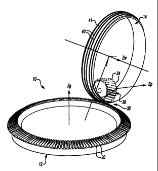
Figure 1 A is a perspective view of a precision grinding apparatus
having a conical face gear and a grinding worm, the precision grinding
apparatus being shown with a theoretical conical involute pinion that has
been superimposed onto the conical face gear and the grinding worm;
Figure 1 B is a top view of the precision grinding apparatus of Figure
1A;
Figure 2A is a side elevation view of the precision grinding apparatus
of Figure 1A, with a dressing tool being shown superimposed to the conical
face gear, the grinding worm and the theoretical conical involute pinion;
Figure 2B is an enlarged view of a portion of Figure 2A;
Figure 2C is an enlarged portion of Figure 2B illustrating the
positioning of the dressing tool against the flank of a reference tooth of the
theoretical conical involute pinion;
Figure 3 is a perspective view of the theoretical conical involute
pinion;
Figure 4 is a perspective view of the dressing tool;
Figure 5A is a perspective view of the precision grinding apparatus of
Figure 1 A, illustrating several geometric references that are employed in the
dressing of the grinding worm and grinding of the conical face gear;
Figure 5B is a bottom view of the grinding worm illustrated in Figure
1 A, illustrating several geometric references that are employed in the
dressing of the grinding worm and grinding of the conical face gear;
Figure 6 is a perspective view of a multi-axis CNC grinding machine
for carrying out the methods of the present invention.
-6-
CA 02366715 2005-02-24
DETAILED DESCRIPTION OF THE PREFERRED EMBODIMENT
With reference to Figures 1 A, 1 B, 2A and 2B of the drawings, a
precision grinding apparatus constructed and operated in accordance with
the teachings of the present invention is generally indicated by reference
numeral 10. Precision grinding apparatus 10 is shown to include a conical
face gear 12, a grinding worm 14 and a dressing tool 16. The conical face
gear 12 includes a plurality of teeth 20 that are adapted to meshingly engage
a plurality of teeth 24 of a conical involute pinion 30. The pinion 30 and the
conical face gear 12 constitute a conical face gear drive 32 in which the
pinion 30 rotates about a pinion axis Zp and the conical face gear 12 rotates
about a face gear axis Z9. The conical involute pinion 30 is employed in the
methodologies disclosed herein as a theoretical reference and as such, is
referred to as being a "theoretical conical involute pinion" since it is not
physically present. The theoretical conical involute pinion 30 is employed in
the dressing and grinding processes disclosed herein as a reference for
positioning the grinding worm 14 relative to the conical face gear 12 and for
positioning the dressing tool 16 relative to the grinding worm 14.
The conical face gear 12 is preferably pre-formed and hardened in a
heat-treatment operation, such as carburizing or nitriding, and includes
excess stock that will be removed in a finishing operation performed by the
precision grinding apparatus 10. As those skilled in the art will understand,
excess stock is necessary to permit the distortions that occur during the heat
treatment of the conical face gear 12 to be satisfactorily attenuated or
eliminated.
In the presently preferred embodiment, the grinding worm 14 is
formed from an abrasive-medium type material, such as aluminum oxide, a
dressable CBN-type or other types of material that are conventionally used
in the manufacture of other types of gears. The grinding worm 14 rotates
about a grinding worm z-axis ZW with a grinding worm angular velocity wW. In
synchronization with the rotation of grinding worm 14, the conical face gear
12 rotates about the conical face gear axis Z9 with a face gear angular
velocity of c~.
_7_
CA 021366715 2005-02-24
In the particular example provided, a plurality of grinding worm teeth
40 that are formed by a single spiral thread 41 contact the conical face gear
12 when the conical face gear 12 and the grinding worm 14 are
synchronously rotating, with each of the grinding worm teeth 40 passing
between a pair of the face gear teeth 20. A single, spiral gap 42 that results
from the single thread 41 runs along the outer perimeter of the grinding
worm 14 between the grinding worm teeth 40. The spiral gap 42 serves to
process the grinding worm 14 over the various face gear teeth 20.
Specifically, as the conical face gear 12 and grinding worm 14
synchronously rotate with rotational velocities of c~ and wW, respectively, a
given face gear tooth 20 enters the spiral gap 42 and travels within the
spiral
gap 42 for several rotations of the grinding worm 14, until the given face
gear
tooth 20 exits the spiral gap 42. The spiral gap 42 begins at one end of the
grinding worm 14 and ends at the opposite end of the grinding worm 14.
Those skilled in the art will understand that the plurality of grinding worm
teeth 40 may alternately be formed by a plurality of threads or spiral gaps 42
that are formed into the grinding worm 14.
In the presently preferred embodiment, the grinding worm 14 not only
rotates about axis Zw synchronously with the rotation of the conical face gear
12, but also moves radially over the conical face gear 12, with the motion
being
termed "feed motion". The feed motion preferably causes the grinding worm to
move radially from the outer end of the face gear teeth 20 to the inner end of
the face gear teeth 20 to thereby ensure that the whole face width of the face
gear teeth 20 is precisely ground by the grinding worm 14. In the presently
preferred embodiment, the grinding worm moves in the radial direction at a
predetermined feed rate (i.e., feed amount per revolution of the conical face
gear 12) that is designed to satisfy the accuracy requirements for the
finished
face gear teeth 20. The direction of the feed motion is determined by the
orientation of the teeth 24 of the conical involute pinion 30. Those skilled
in the
art will understand that the feed motion may be reversed (i.e., from the inner
end to the outer end of the face gear teeth 20) as may deemed more
appropriate in certain situations.
_g_
CA 021366715 2005-02-24
In Figure 3, the features of the conical involute pinion 30 are illustrated
in detail. The orientation of the teeth 24 of the pinion 30 is determined by
two
design parameters: the skew angle ~ and the half-cone angle 8. For
reference purposes, a vector designated by i is attached to and aligned with a
reference tooth 33, with the vector i emanating from the mid-height location
34
of the reference tooth 33. The tooth flanks 35 of the conical involute pinion
30
are surfaces of an involute helicoid generated from a base cylinder. A series
of
straight generators 28 are located on the involute helicoid tooth surfaces,
covering the whole of the tooth flanks 35. Along any given generator 28, the
tooth surface normal vector np is tangent to the base cylinder 36 (a
theoretical
design parameter) from which the involute helicoid is generated.
In Figure 4, the preferred shape of the dressing tool 16 is illustrated to
include a flat front surface 60 that is employed to form and maintain the
thread
profile of the grinding worm 14. With additional reference to Figures 2A and
2B, the positioning of the dressing tool 16 relative to the grinding worm
teeth
40 is shown, along with the theoretical conical involute pinion 30 and the
mating conical face gear 12 which serve as references for the initial
positioning
of the grinding worm 14 and the dressing tool 16. Those skilled in the art
will
understand that during the dressing operation, the theoretical conical
involute
pinion 30 and the conical face gear 12 are not physically present (i.e., not
in
meshing engagement with the grinding worm 14). Once the dressing tool 16 is
placed in its initial position relative to the grinding worm 14, the grinding
worm
14 is rotated about axis ZW while the dressing tool 16 is moved in a linear
manner along a direction normal to the flat surface 60.
The dressing operation is performed in several operational passes, with
each pass consisting of the steps of: determining an initial position of the
dressing tool 16 and the grinding worm 14; positioning the dressing tool 16
and
the grinding worm 14 at the initial position; synchronously moving the
dressing
tool 16 in a linear manner and rotating the grinding worm 14 so that the
dressing tool 16 contacts the entire depth of the grinding worm thread 40; and
withdrawing the dressing tool 16 from the grinding worm tooth 40. The next
pass will employ a new initial position for the dressing tool 16 and a new
_g_
CA 021366715 2005-02-24
direction of linear motion, but the new direction of linear motion is always
normal to the flat surface 60, and the ratio of the angular velocity of the
grinding worm 14 and the linear velocity of the dressing tool 16 remains
constant throughout the dressing operation. Multiple dressing passes are
necessary to form and/or dress the entire grinding worm tooth 40. In the
particular example provided, the dressing operation is performed first on one
side of the grinding worm 14 to generate a first side of the grinding worm
tooth
40 and thereafter on a second side of the grinding worm 14 to generate the
second side of the grinding worm tooth 40.
In Figure 5A, the installation of the grinding worm 14 is illustrated in side
elevation. For purposes of discussion, several auxiliary geometric features
that
serve as references in specifying the position and/or motion of the grinding
worm 14 and the dressing tool 16 are also shown.
A vector, designated by reference letter d, identifies the shortest
distance between the rotational axis Zp of the pinion 30 and the rotational
axis
Z9 of the conical face gear 12. A first plane, generally indicated by
reference
letter A, passes through the rotational axis Zp of the pinion 30 and is
perpendicular to vector d. A line, designated as CC, is located on plane A
and is perpendicular to the pinion axis Zp. The pinion 30 is initially
positioned such that the vector t that is attached to the reference tooth 33
and illustrated in Figure 3 intersects line CC at point Fo, located at the mid-
point of the face width of the conical face gear 12. From point Fo a vector,
designated as vector F , is generated in a manner such that it is aligned with
the current orientation of vector t . Generated in this manner, vector F is
fixed in space and serves as a reference for installing or positioning the
grinding worm 14 to the conical face gear 12 and as the feed direction for
the feed motion of the grinding worm 14 across the face width of the face
gear teeth 20.
The installation of the grinding worm 14 is determined by a vector l
that is contained in plane A, emanating from point Fo in a direction
perpendicular to vector F . The length of vector l is determined by the
reference pitch diameter (DW) of the grinding worm 14, with the reference
-10-
CA 021366715 2005-02-24
pitch diameter being the diameter of the circle that is offset from the outer
diameter of the grinding worm 14 by the amount of addendum of the thread
on the grinding worm, according to equation (1 ):
~ l~ _ (DWG 2) (1)
With additional reference to Figure 5B, the axis of rotation Zw of the
grinding worm 14 is installed at the end of vector l such that it is
perpendicular to vector l and the angle between the axis of rotation Zw of
the grinding worm 14 and vector F is yew. The angle ~w is related to the lead
angle ~, w of the grinding worm 14 by equation (2):
yrw= 90°- ~,w
(2)
Those skilled in the art will understand that in installing the grinding worm
14,
the angle y~W should be measured in proper orientation according to the
hand-type (i.e., left or right hand) of the grinding worm 14. The lead angle
~,
w is determined by equation (3):
~.w - sm ' ~ D P ~ (3)
w d
where Nw is the number of threads 41 on the grinding worm 14, Dw is the
reference pitch diameter of the grinding worm 14 and Pd is the diametrical
pitch
of the conical face gear set (i.e., the conical face gear 12 and the pinion
30).
With the grinding worm installation given above, the generation of the
conical face gear 12 is carried out with two motions of the grinding worm 14
relative to the conical face gear 12. The first motion is synchronous rotation
of
both the grinding worm 14 and the conical face gear 12 about their respective
axes of rotation Zw and Z9. The angular velocities of the grinding worm 14 and
the conical face gear 12 are related as provided in equation (4):
Nw (4)
~w Ng
where c~ is the angular velocity of the conical face gear 12, wW is the
angular
velocity of the grinding worm and N9 is the number of teeth 20 on the conical
face gear 12. As the conical face gear 12 and grinding worm 14 rotate
_11_
CA 02366715 2005-02-24
synchronously, the motion in which the grinding worm 14 is fed across the face
width of the face gear teeth 20 proceeds along the feed direction (as defined
by vector F ), preferably starting from the outer end of the conical face gear
12
and moving towards the inner end of the face gear teeth 20. As noted above,
this motion may also be reversed if deemed appropriate under certain
conditions. The magnitude of the feed motion, or the amount of movement
along the vector F per revolution of the conical face gear 12, is determined
by
a predetermined set of accuracy requirements for the face gear teeth 20 that
are being ground. Those skilled in the art will readily understand how to
control the magnitude of the feed motion so as to satisfy set of accuracy
requirements and as such, this need not be discussed in more detail.
The profile of the grinding worm teeth 40 is formed and maintained by
the dressing tool 16, with the flat surface 60 being made of an appropriate
material such as diamond grit that is implanted in a bounding base material.
Referring back to Figures 2A and 2B, the dressing tool 16 is illustrated as
being located in the spiral gap 42, with the dressing tool 16 and the grinding
worm 14 being oriented in a first initial position relative to the conical
face gear
12. The initial reference position of the grinding worm 14 is determined by
using pinion 30 as a reference as described above. The position of the flat
surface 60 of the dressing tool 16 and the synchronous motion of the dressing
tool 16 and grinding worm 14 are detailed by the following procedure, wherein
the conical face gear 12 is used as a stationary, theoretical reference and is
not physically present (i.e., not contacting the grinding worm 14) during the
dressing operation:
a) Referring to Figure 3, the vector i is aligned with the orientation
of the reference tooth 33 and attached thereto at the mid-height of the
reference tooth 33 as discussed above.
b) Referring to Figures 5A and 5B, superimposing the theoretical
conical involute pinion 30 to the conical face gear 12 and the grinding worm
14
in the manner discussed above and thereafter establishing point Fo and vector
F.
-12-
CA 02366715 2005-02-24
c) Referring to Figures 2A, 2B and 3, locating a straight generator
28a on one of the flanks 35a of the reference tooth 33 and placing the flat
surface 60 of the dressing tool 16 in tangent contact with the flank 35a of
the
reference tooth 33 along the straight generator 28a such that the normal ~ of
the flat surface 60 is aligned with the normal np of the reference tooth 33 at
the
given generator 28a.
d) Referring to Figures 1 B and 2A through 2C, rolling the theoretical
conical involute pinion 30 over the conical face gear 12, which is assumed to
be fixed at this stage, such that the pinion teeth 24 maintain tangent contact
the face gear teeth 20 and the theoretical conical involute pinion 30 and the
conical face gear 12 obey true conjugate action. This rotation causes the
rotational axis Zp of the theoretical conical involute pinion 30 to rotate
about the
rotational axis Z9 of the conical face gear 12, with the amount of rotation
being
equal to an angle Ocpz9 that is obtained from the mathematical condition
detailed in the vectorial scalar product equation (5):
n~F=0. (5)
As those skilled in the art will understand, the solution of the angle OcpZ9
is a
simple mathematical problem since the rotational axis Z9 of the conical face
gear 12, the (nominal) rotational axis Zp of the theoretical conical involute
pinion 30, the feed direction vector l~ and the surface normal np of the given
generator 28 on the reference tooth 33 are all well defined as discussed
above. Those skilled in the art will understand that the angle OcpZ9 is
greatly
exaggerated in Figure 1 B for the purposes of illustration only and that in
practice, the angle ~cpZ9 is typically relatively small.
e) Simultaneously with the rotation of the pinion rotational axis Zp about
the rotational axis Z9 of the conical face gear 12, the theoretical conical
involute
pinion 30 rotates through an angle ocp~ about the pinion rotational axis ZP,
with
the magnitude of the angle OcpZp being defined by the relationship defined by
equation (6):
O~PzP -_ Ng -_ O.s
O~pZg N p OSpZg rb cos t/ib
-13-
CA 02366715 2005-02-24
where Np is the number of teeth on the theoretical conical involute pinion 30
and N9 is the number of teeth on the conical face gear 12. The remaining
variables (i.e., Os, rb and yrt,) will be discussed in detail in step f),
below.
f) Simultaneous with steps d) and e), above, the dressing tool 16 is
moved three-dimensionally such that the flat surface 60 maintains tangent
contact with the surface of the flank 35a of the reference tooth 33 by
performing the same angular movement (OcpZ9) about the rotational axis Z9 of
the conical face gear 12 and translates by a distance 0s along its own normal
n with Os being determined through equation (6). Referring back to the
relationship defined by equation (6), rb is the radius of the base cylinder of
the
pinion 30 and y~ is the base helix angle as shown in Figure 3.
g) After the adjustments to the positions of the theoretical conical
involute pinion 30 and the dressing tool 16 have been made, the grinding worm
14 and the dressing tool 16 are synchronously moved, such that the grinding
worm 14 rotates about its rotational axis Zw and the dressing tool 16
translates
in the direction of the normal n of the flat surface 60, with the velocity vd
of the
dressing tool 16 being related to the angular velocity ww of the grinding worm
14 by equation (7):
Vd = NW Yb COS 1~/bCOr, . 7
P
The procedure defined by steps a) through g) determines a single path
of the dressing tool 16 in forming a single surface of the grinding worm teeth
40. The procedure places the dressing tool at a predetermined initial position
and controls the simultaneous movement of the dressing tool 16 and the
grinding worm 14.
In practical implementation, it is preferred that the dressing tool 16 start
at a point on the determined tool path that is not in contact with the
grinding
worm 14, move in the manner defined above so as to contact the grinding
worm 14 and travel through the entire length of the spiral gap 42 and
thereafter
be withdrawn from the grinding worm 14. Thereafter, the procedure defined by
steps a) through g) is repeated many times, with each iteration of the
procedure using a different one of the straight generators 28 on the reference
-14-
i
CA 02366715 2005-02-24
tooth 33, until a first side of the grinding worm teeth 40 is formed. The
procedure is then repeated to form the second side of the grinding worm teeth
40. In the particular example provided, approximately forty different straight
generators 28 were employed on each side of the reference tooth 33 to define
the paths of the dressing tool 16 in forming the grinding worm teeth 40. Those
skilled in the art will readily understand, however, that the number of
straight
generators 28 that are employed to define the paths of the dressing tool 16
can
be selected to provide a desired level of accuracy; more straight generators
28
may be employed if a higher degree of accuracy is desired, while fewer
straight generators may be employed if a lesser degree of accuracy is
required. Those skilled in the art will also understand that the amount of
time
to fully dress the grinding worm 14 will vary depending on the number of
straight generators 28 that are being employed to define the paths of the
dressing tool 16.
With reference to Figure 6, a multi-axis CNC (computer numerical
control) grinding machine 100 for performing the dressing and grinding
methods of the present invention is illustrated. The grinding worm 14 is
mounted on a tool spindle 102 and rotates in the direction of arrow C. The
tool
spindle 102 is mounted to a translating table 104, permitting the rotary axis
of
the tool spindle 102 to be moved in a desired manner along three linear axes,
X, Y and Z, which in the particular example illustrated are oriented in an
orthogonal relationship. The conical face gear 12 is mounted on a rotary table
108 and rotates in the direction of arrow A. The dressing tool 16 is mounted
to
a swing table 112 and is rotatable as shown by arrow B. The location of the
tool spindle 102 relative to the rotary table 108 and the dressing tool 16 (in
the
X, Y and Z directions) is controlled by translating table 104.
Relative positions and movements between the grinding worm 14, the
dressing tool 16 and the conical face gear 12 are calculated in the manner
discussed above, providing a series of coordinates and paths that are
employed to generate a NC (numerical control) program to control the
movements of the tool spindle 102, the translating table 104, the rotary table
108 and the swing table 112. Execution of the NC program will then dress the
-15-
CA 021366715 2005-02-24
grinding worm 14 and grind the conical face gear 12 in the manner described
above. Accordingly, with the dressing and grinding methods of the present
invention, the process of converting into machine coordinates and generating
NC programs may be accomplished with commercially available CAM
(computer-aided-manufacturing) software packages and NC post-processors
customized for the design configuration of the grinding and dressing machine
that is used.
While the invention has been described in the specification and
illustrated in the drawings with reference to a preferred embodiment, it will
be
understood by those skilled in the art that various changes may be made and
equivalents may be substituted for elements thereof without departing from the
scope of the invention as defined in the claims. In addition, many
modifications
may be made to adapt a particular situation or material to the teachings of
the
invention without departing from the essential scope thereof. Therefore, it is
intended that the invention not be limited to the particular embodiment
illustrated by the drawings and described in the specification as the best
mode
presently contemplated for carrying out this invention, but that the invention
will
include any embodiments falling within the foregoing description and the
appended claims.
-16-