Language selection

Search

Patent 2366773 Summary

Third-party information liability

Some of the information on this Web page has been provided by external sources. The Government of Canada is not responsible for the accuracy, reliability or currency of the information supplied by external sources. Users wishing to rely upon this information should consult directly with the source of the information. Content provided by external sources is not subject to official languages, privacy and accessibility requirements.

Claims and Abstract availability

Any discrepancies in the text and image of the Claims and Abstract are due to differing posting times. Text of the Claims and Abstract are posted:

  • At the time the application is open to public inspection;
  • At the time of issue of the patent (grant).
(12) Patent: (11) CA 2366773
(54) English Title: ADJUSTABLE SPINAL TETHER
(54) French Title: ELEMENT DE FIXATION VERTEBRALE REGLABLE
Status: Deemed expired
Bibliographic Data
(51) International Patent Classification (IPC):
  • A61B 17/70 (2006.01)
(72) Inventors :
  • DREWRY, TROY D. (United States of America)
  • SHERMAN, MICHAEL C. (United States of America)
  • BRUMFIELD, DAVID (United States of America)
(73) Owners :
  • WARSAW ORTHOPEDIC, INC. (United States of America)
(71) Applicants :
  • SDGI HOLDINGS, INC. (United States of America)
(74) Agent: SMART & BIGGAR
(74) Associate agent:
(45) Issued: 2008-02-12
(86) PCT Filing Date: 2000-03-22
(87) Open to Public Inspection: 2000-11-02
Examination requested: 2005-03-18
Availability of licence: N/A
(25) Language of filing: English

Patent Cooperation Treaty (PCT): Yes
(86) PCT Filing Number: PCT/US2000/007664
(87) International Publication Number: WO2000/064363
(85) National Entry: 2001-10-04

(30) Application Priority Data:
Application No. Country/Territory Date
60/130,910 United States of America 1999-04-23
09/421,976 United States of America 1999-10-20

Abstracts

English Abstract


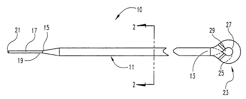
An improved apparatus is provided to allow for an adjustable length tether
(10) for use in the spine and other parts
of the body. The tether (10) comprises an artificial strand (11) with an
eyelet (23) formed in one end (13), the other end (15) being
looped through the eyelet (23). The other end (15) is then secured with
respect to the eyelet (23) by a crimp (50), the excess length
being cut off after the length of the tether (10) has been given an
appropriate tension. Alternatively, the eyelet end (13) may be formed
around a grommet (123). The crimp (50) may be separate from the grommet (123)
or a part of the grommet (123). The mechanism
by which the length is adjusted in some cases will take advantage of the shape
memory properties of alloys such as nickel-titanium.


French Abstract

L'invention concerne un appareil amélioré permettant l'utilisation d'un élément de fixation (10) de longueur réglable dans la colonne vertébrale et d'autres parties du corps. Ledit élément de fixation (10) est constitué d'un fil artificiel (11) dans une extrémité duquel un oeillet (23) est formé, l'autre extrémité (15) passant dans l'oeillet (23) en formant une boucle. L'autre extrémité (15) est ensuite fixée par rapport à l'oeillet (23), au moyen d'un accouplement de serrage (50), la longueur excédentaire étant coupée une fois qu'une tension appropriée a été appliquée sur la longueur de la fixation (10). Autrement, l'extrémité (13) à oeillet peut être formée autour d'un oeillet de fixation (123). L'accouplement de serrage (50) peut être séparé de l'oeillet de fixation (123) ou d'une partie de celui-ci (123). Le mécanisme utilisé pour le réglage de la longueur exploite, dans certains cas, les propriétés de mémoire de forme d'alliages, tels que le nickel-titane.

Claims

Note: Claims are shown in the official language in which they were submitted.


24

CLAIMS:


1. ~An adjustable spinal tether, comprising:
a polymer strand (11, 11b, 11c, 111, 111b, 111c) having a first end
portion (13, 13b, 13c, 113, 113b, 113c) and a second end portion (15, 115),
said first end portion (13, 13b, 13c, 113, 113b, 113c) defining an aperture
(29, 29b, 29c, 133, 233, 333, 433), said second end portion (15, 115)
extending through said aperture (29, 29b, 29c, 133, 233, 333, 433) to form
a loop having an adjustable length; and
a crimp (50, 70, 70a, 135, 170) having a passage (55, 75, 175)
defined therethrough, said crimp (50, 70, 70a, 135, 170) being
transitionable from a first state to a second state, said first state
providing said passage (55, 75, 175) with a size that permits said
second end portion (15, 115) to pass through said passage (55, 75, 175),
said second state providing said passage with a size that prevents said
second end portion (15, 115) from passing through said passage (55, 75,
175), a portion (51, 71, 136, 171) of said crimp (50, 70, 70a, 135, 170)
having a cross section that prevents said crimp (50, 70, 70a, 135, 170)
from passing through said aperture (29, 29b, 29c, 133, 233, 333, 433).

2. The adjustable spinal tether of claim 1, wherein said crimp
(50, 70, 70a, 135, 170) is displaceable along said second end portion (15,
115) of said strand (11, 11b, 11c, 111, 111b, 111c) relative to said aperture
(29, 29b, 29c, 133, 233, 333, 433) when in said first state, said crimp (50,
70, 70a, 135, 170) being positioned adjacent said aperture (29, 29b, 29c,
133, 233, 333, 433) and transitioned to said second state to fix said length
of said loop.


3. ~The adjustable spinal tether of claim 1, wherein said polymer
strand (11, 11b, 11c, 111, 111b, 111c) includes an inner core (32) and an
outer sheath (31).


25

4. The adjustable spinal tether of claim 3, wherein each of said
inner core (32) and said outer sheath (31) are formed of a braided polymer.
5. The adjustable spinal tether of claim 3, wherein said inner
core (32) is formed of polyester.

6. The adjustable spinal tether of claim 3, wherein said inner
core (32) is formed of polyethylene.

7. The adjustable spinal tether of claim 3, wherein said inner
core (32) is braided.

8. The adjustable spinal tether of claim 3, wherein said outer
sheath (31) is formed of polyester.

9. The adjustable spinal tether of claim 3, wherein said outer
sheath (31) is formed of polyethylene.

10. The adjustable spinal tether of claim 3, wherein said outer
sheath (31) is braided.

11. The adjustable spinal tether of claim 1, wherein said polymer
strand (11, 11b, 11c, 111, 111b, 111c) is a monofilament polymer strand
(11, 11b, 11c, 111, 111b, 111c).

12. The adjustable spinal tether of claim 1, wherein said polymer
strand (11, 11 b, 11 c, 111, 111b, 111c) is a multifilament polymer strand
(11, 11b, 11c, 111, 111b, 111c).


26

13. The adjustable spinal tether of claim 1, wherein said
adjustable spinal tether further comprises a leader (17, 117) attached to
said second end portion (15, 115).

14. The adjustable spinal tether of claim 13, wherein said leader
(17, 117) is formed of titanium.

15. The adjustable spinal tether of claim 13, wherein said leader
(17, 117) is at least partially formed of a shape memory material.

16. The adjustable spinal tether of claim 13, wherein said leader
(17, 117) is formed of a polymer, said leader (17, 117) being formed
integral with said second end portion (15, 115) of said polymer strand (11,
11b, 11c, 111, 111b, 111c).

17. The adjustable spinal tether of claim 1, wherein said second
end portion (15, 115) of said polymer strand (11, 11b, 11c, 111, 111b,
111c) extends through said aperture (29, 29b, 29c, 133, 233, 333, 433)
only once.

18. The adjustable spinal tether of claim 1, wherein said first end
portion (13, 13b, 13c, 113, 113b, 113c) of said polymer strand (11, 11b,
11c, 111, 111b, 111c) is secured in wrapped condition to form an eyelet
(23, 23b, 23c), said eyelet (23, 23b, 23c) defining said aperture (29, 29b,
29c).

19. The adjustable spinal tether of claim 18, wherein said first end
portion (13, 13b, 13c, 113, 113b, 113c) includes a first part and a second
part; and


27

further comprising means for attaching said first part to said second
part to form said eyelet (23, 23b, 23c).

20. The adjustable spinal tether of claim 18, wherein said first end
portion (13c, 113c) includes a first part and a second part; and
wherein said first part is attached to said second part by an adhesive
to form said eyelet (23c).

21. The adjustable spinal tether of claim 18, wherein said first end
portion (13b, 113) includes a first part and a second part; and
wherein said first part is attached to said second part by a thread
(34, 134) sewn around said first and second parts to form said eyelet (23b).
22. The adjustable spinal tether of claim 18, wherein said first end
portion (113b) includes a first part and a second part; and
wherein said first part is attached to said second part by swaging
said first and second parts together to form said eyelet (23, 23b, 23c).

23. The adjustable spinal tether of claim 18, wherein said first end
portion (13c, 113c) includes a first part and a second 'part; and
wherein said first part is attached to said second part by melting at
least a portion of each of said first and second parts and fusing the melted
portions together to form a solidified polymer.

24. The adjustable spinal tether of claim 1, wherein said crimp
(50) has external threading (52), said crimp (50) including a nut (65)
threadable along said external threading (52) to transition said crimp (50)
between said first and second states.


28

25. The adjustable spinal tether of claim 1, wherein at least a
portion of said crimp (70, 70a, 135, 170) is formed of a shape memory
material, said at least a portion of said crimp (70, 70a, 135, 170) being
reformable between a first configuration and a second configuration, said
first configuration corresponding to said first state to permit said second
end portion (15, 115) to pass through said passage (75, 175), said second
configuration corresponding to said second state to prevent said second
end portion (15, 115) from passing through said passage (75, 175).

26. The adjustable spinal tether of claim 25, wherein said crimp
(70, 70a, 170) includes a first branch (73, 73a, 173) and an opposite
second branch (74, 74a, 174), said first and second branches (73, 73a,
173, 74, 74a, 174) being disposed closer to one another in said second
configuration than in said first configuration, said first and second branches

(73, 73a, 173, 74, 74a, 174) being compressed about said second end
portion (15, 115) of said polymer strand (11, 11b, 11c, 111, 111b, 111c)
when reformed from said first configuration toward said second
configuration.

27. The adjustable spinal tether of, claim 25, wherein said at least
a portion of said crimp (50, 70, 70a, 135, 170) is reformable between said
first and second configurations without a corresponding change in
temperature.
28. The adjustable spinal tether of claim 25, wherein said at least
a portion of said crimp (70a) is a compression member (81) at least
partially formed of said shape memory material, said compression member
(81) co-acting with the remainder of said crimp (70a) to provide said first
and second configurations.


29

29. The adjustable spinal tether of claim 28, wherein said crimp
(70a) has an outer surface (78) defining a groove (80), said compression
member (81) being disposed within said groove (80).

30. The adjustable spinal tether of claim 1, wherein said passage
(55, 75, 175) is bounded by an interior surface (57, 77, 177), said interior
surface (57, 77, 177) defining a plurality of grooves to aid in preventing
said
second end portion (15, 115) from passing through said passage (55, 75,
-175) when said crimp (50, 70, 70a, 170) is transitioned from said first state

toward said second state.

31. The adjustable spinal tether of claim 1, wherein said passage
(55, 75, 175) in said crimp (50, 70, 70a, 135, 170) is tapered.

32. The adjustable spinal tether of claim 1, wherein said passage
(55, 75, 175) in said crimp (50, 70, 70a, 135, 170) is bounded by a side
wall, said side wall defining a slot (178) extending from one end (176) of
said crimp (50, 70, 70a, 135, 170) toward an opposite end (172) of said
crimp (50, 70, 70a, 135, 170).

33. The adjustable spinal tether of claim 32, wherein said slot
(178) has an undulating shape.

34. The adjustable spinal tether of claim 32, wherein said slot
(178) is S-shaped.

Description

Note: Descriptions are shown in the official language in which they were submitted.


CA 02366773 2006-11-06
51344-3

1
ADJUSTABLE SPtNAL TETHER
BACKGROUND OF THE INVENTION
Various types of spinal column disorders are known and include
scoliosis (abnormal curvature of the spine), kyphosis (backward curvature
of the spine), spondylolisthesis (forward displacement of a lumbar
vertebra), and other disorders such as ruptured or slipped discs, broken or
fractured vertebrae, and the like. Procedures to stabilize areas of the spine
for both fusing spinal vertebrae together and for other stabilization
purposes often require the use of a spinal tether. The existing spinal
tethers, of which we are aware on the market, come in straight lengths or
circular, "loop" geometries. These tethers typically rely on implants,
anchors, or knots to secure the tether to the spine. Additionally, such
implants are of fixed length requiring careful measurement of the distance
around the anatomy to which the tether is secured or between the anchor
points to which the tether is attached. Such precise measurement is
difficult prior to surgery and, when done during surgery, results in longer
operating times as measurements are taken and a spinal tether of the
appropriate length is manufactured.


VVO 00/64363 CA 02366773 2001-10-04 PCT/US00/07664
2

SUMMARY OF THE INVENTION

In one embodiment, the apparatus comprises an adjustable tether
having a polymer strand with a first end and a second end and a first end
portion and second end portion between the first end and the second end.
The polymer strand has an intermediate portion between the end portions.
The first end is secured in wrapped condition to form an eyelet in the first
end portion. The eyelet has a first side and a second side and an aperture
defined between the first side and the second side. The aperture has a
cross-section such that the second end may pass therethrough in the
direction from one of the sides to the other of the sides. The apparatus
further includes a crimp with a bore detined therethrough. The intermediate
portion of the tether extends through the bore. The crimp has a first portion
with a cross-section such that the first portion will not pass through the
aperture. The crimp has a first state and a second state, the first state
permitting the polymer strand to move within the bore, the second state
locking the intermediate portiori within the bore wherein the intermediate
portion is received in the bore only once.
In another embodiment, the apparatus comprises an adjustable
tether having a polymer strand with a first part and a second part, each of
the parts between a first end portion and a second end portion. The first
part is closer to the first end portion than the second part. The first end
portion is wrapped around and contacts the first part to form an eyelet with
a first side and a second side. The apparatus has attachment means for
holding the first end portion in contact with the first part. The eyelet has
an
aperture defined between the first side and the second side, the aperture
having a cross-section such that the second end may pass therethrough.
The second end portion passes through the aperture in the direction from
the first side to the second side to form a loop with a length and the
apparatus has means for fixing the length of the loop.


CA 02366773 2006-11-06
51344-3

3
In another embodiment, the apparatus comprises a grommet with a
top surface and a bottom surface and interior and exterior side surfaces
extending between the top surface and the bottom surface. The interior
side surface defines an aperture between the top surface and the bottom
surface. The apparatus also includes an artificial strand having a first end
portion and a second end portion. The first end portion is attached to the
grommet and the second end portion passes through the aperture in a
direction from the bottom surface to the top surface to form a loop. The
apparatus further includes a crimp with a bore defined therethrough, the
second end portion passing through the bore.' The crimp has a first portion
with a cross-section such that-the first portion of the crimp will not pass
through the aperture. The crimp has a first state and a second state. The
first state permits the artificial strand to move within the bore, the second
state locks a portion of the artificial strand within the bore.
In yet another embodiment the apparatus comprises a grommet with
a top surface and a bottom surface and interior and exterior side surfaces
extending between the top surface and the bottom surface. The interior
side surface defines an aperture between the top surface and the bottom
surface. The apparatus also includes an artificial strand with a first end
portion and a second end portion and means for attaching the first end
portion to the grommet. The second end portion passes through the
aperture in a direction from the bottom surface to the top surface to form a
loop.


CA 02366773 2006-11-06
51344-3

3a
Thus, in one aspect the invention provides an
adjustable spinal tether, comprising: a polymer strand
having a first end portion and a second end portion, said
first end portion defining an aperture, said second end

portion extending through said aperture to form a loop
having an adjustable length; and a crimp having a passage
defined therethrough, said crimp being transitionable from a
first state to a second state, said first state providing
said passage with a size that permits said second end

portion to pass through said passage, said second state
providing said passage with a size that prevents said second
end portion from passing through said passage, a portion of
said crimp having a cross section that prevents said crimp
from passing through said aperture.


WO 00/64363 CA 02366773 2001-10-04 PCT/US00/07664
4

BRIEF DESCRIPTION OF THE DRAWINGS
FIG. 1A is a side elevational view of the adjustable tether of an
embodiment of the adjustable tether of the present invention.
FIG. 1 B is a top view of the embodiment of FIG. 1 A.
FIG. 2 is a cross-sectional view of the strand of the embodiment of
FIG. 1 B along the lines 2-2.
FIG. 3 is an enlarged partial view of an embodiment of the
adjustable tether in which one end is wrapped around and sewn with a
thread.
FIG. 4 is a close up of one end portion of the adjustable tether which
is wrapped around and joined along a contact surface.
FIG. 5 is illustrative of the flexibility of one embodiment of the
artificial strand of the adjustable tether.
FIG. 6 is ari enlarged view of the interconnection between a leader
and an artificial strand.
FIGS. 7A-D are side, side, top, and perspective views respectively of
another embodiment of the adjustable tether.
FIG. 8 is an enlarged cross-sectional view of the crimp arid locknut
of the embodiment of FIG. 7.
FIG. 9A is a side elevational view of the crimp of FIG. 7.
FIG. 9B is another side elevational view of the adjustable tether of
FIG. 7.
FIG. 9C is a bottom plan view of the crimp of FIG. 7.
FIG. 9D is a cross-sectional view of the crimp of FIG. 7 along the
direction 9d in FIG. 9A.
FIG. 9E is a cross-sectional view of FIG. 9A along the direction 9d
when the crimp is in its deformable first state to more easily allow the
artificial strand to extend through the bore in the mechanical crimp.
FIGS. 10A and 10B are side views with sectional view drawn in
phantom lines of a shape memory crimp for use with an embodiment of the
adjustable tether.


WO 00/64363 CA 02366773 2001-10-04 PCT/USOO/07664

FIGS. 11A-C are side views with sectional view drawn in phantom
lines of another embodiment of the crimp using shape memory technology.
FIG. 12A is a side elevational view of an adjustable tether with a
grommet at one end having a socket receiving a ball portion of a crimp.
5 FIG. 12B is an enlarged cross-sectional view of the ball and socket
crimp-grommet of FIG. 12A.
FIG. 13A is a top plan view of the adjustable tether of the FIG. 12A.
FIG. 13B is an enlarged view of the grommet and crimp end of the
adjustable tether of FIG. 13A.
FIG. 14A is a top plan view of a self-locking grommet.
FIG. 14B is a side view of the self-locking grommet of FIG. 14A.
FIG. 14C is a cross-sectional view along the direction 14c of the self-
locking grommet of FIG 14A.
FIG. 15A is a top plan view of an embodiment of a crimping
grommet.
FIG. 15B is a side view of the embodiment of the crimping grommet
of FIG. 15A.
FIG. 15C is a cross-sectional view along the lines A-A of the
crimping grommet of FIG. 15A.
FIG. 15D is a perspective view of the crimping grommet of FIG. 15A.
FIG. 16A is a top plan view of another embodiment of a crimping
grommet.
FIG. 16B is a side view of another embodiment of the crimping
grommet of FIG. 16A.
FIG. 16C is a cross-sectional view along the direction A-A of the
crimping grommet of FIG. 16A.
FIG. 16D is a perspective view of the crimping grommet of FIG. 16A.
FIG. 17A is an enlarged partial view of the embodiment of the
artificial strand wrapped around a grommet and attached with threading.
FIG. 17B is an enlarged partial view of the artificial strand wrapped
around a grommet and held together with a sleeve.


WO 00/64363 CA 02366773 2001-10-04 PCTIUSOO/07664
6

FIG. 17C is an enlarged partial view of the artificial strand attached
to the grommet along a contact surface.
FIG. 18A is an illustration of a grommet which is a closed ring.
FIG. 18B is an illustration of a grommet of the present invention
which is an open ring.
FIG. 19 is an enlarged partial view of another embodiment of the
adjustable tether having a plug and ring design.
FIGS. 20A and 20B are top views of oval shaped cams interacting
with an artificial strand to tension the artificial strand.
FIGS. 21 A and 21 B are another embodiment of cam tensioners
having a shape other than oval.
FIG. 22A is a side view of another embodiment of a shape memory
tether crimp.
FIG. 22B is another side view of the embodiment of a shape
memory tether crimp of FIG. 22A.
FIG. 22C is a bottom plan view of the crimp of FIG. 22A.
FIG. 22D is an enlarged cross-sectional view of the crimp of FIG.
22A along the direction A-A of FIG. 22A.


WO 00/64363 CA 02366773 2001-10-04 PCTIUSOO/07664
7

DESCRIPTION OF THE PREFERRED EMBODIMENT

For the purposes of promoting an understanding of the principles of
the invention, reference will now be made to the embodiments illustrated in
the drawings and specific language will be used to describe the same. It
will nevertheless be understood that no limitation of the scope of the
invention is thereby intended, such alterations and further modifications in
the illustrated devices, and such further applications of the principles of
the
invention as illustrated therein being contemplated as would normally occur
to one skilled in the art to which the invention relates.
With reference to FIGS. 1 A and 1 B, an adjustable spinal tether 10
comprises a leader 17 attached to an artificial strand 11. Artificial strand
11
has a first end 13 and a second end 15. The totai length L of strand portion
of the tether is preferably about one meter. This length may be varied as
desired. Leader 17 has a first end 19 which is attached to the second end
15 of artificial strand 11. The second end of leader 17 has a tip 21. Tip 21
may be blunt or sharp as desired. The first end portion 13 of artificial
strand 11 is wrapped around and attached to artificial strand 11 to form an
eyelet 23 with a first side 25 and a second side 27 with an aperture 29
defined in the eyelet. The adjustable spinal tether 10 will also include a
crimp (not shown), various embodiments of which will be discussed further
below.
With reference to FIG. 2, the cross-section of one preferred
embodiment of the artificial strand 11 a is a coaxial design with an outer
sheath 31 and an inner core 32. The inner core 32 and outer sheath 31 are
both preferably made of a braided polymer such as polyester,
polypropylene, or polyethylene. The inner core 32 and outer sheath 31
may be made of different polymers. In one embodiment the inner core 32
and outer sheath 31 are both made of polyethylene. In another
embodiment the inner core 32 is braided for strength. In yet another
embodiment, the outer sheath 31 is braided for abrasion resistance. The


CA 02366773 2001-10-04
WO 00/64363 PCT/US00/07664
8
outer sheath is braided for abrasion resistance by weaving it in such a
manner that the outer sheath 31 is unloaded and has no tensile force
applied to it. In a preferred embodiment, the inner core 32 and outer
sheath 31 are both made of polyethylene with the inner core 32 being
braided for strength and the outer sheath 31 being braided for abrasion
resistance. It should be understood that other designs such as multi-
layered designs with a plurality of successive outer sheaths or a
monofilament or single fiber design are within the scope of the invention. It
should be further understood that artificial strand 11 may be manufactured
from a variety of materials, including, but not limited to, conventional
biocompatible implant alloys such as titanium, stainless steel, cobalt-
chrome alloys, or even shape memory alloys and materials such as nickel-
titanium.
With reference to FIG. 3, one embodiment of artificial strand 11 b has
a first end portion 13b which is wrapped back around on artificial strand
11 b to form an eyelet 23b with a first side 25b and a second side 27b
defining an aperture 29b in the eyelet. In this embodiment the first end
portion 13b is sewn by threading 34 to attach it to artificial strand 11 b.
With
reference to FIG. 4, in another embodiment artificial strand 11 c has a first
end portion 13c wrapped back around itself to form an eyelet 23c with an
aperture 29c having a first side 25c and a second side 27c. In the
embodiment in FIG. 4 the first end portion 13c contacts the artificial strand
11 c along a line or surface 35. The first end portion 13c may be attached
or coupled along contact portion 35 to the artificial strand 11 c in a variety
of
manners. For example, a crimp (not shown) encircling part or all of both
strand 11c and first end portion 13c may hold the loop/eyelet formation.
Alternatively, an adhesive could be applied on first end portion 13c and
strand 11 c at contact portion 35 to hold first end 13c in a loop
configuration
with eyelet 23c. In other possible embodiments first end portion 13c could
be swaged, press fit, or even welded against 11 c if strand 11 is a metal, to
secure it. In yet another embodiment the strand 11 c is a polymer as is first


WO 00/64363 CA 02366773 2001-10-04 PCT/US00/07664
9

end portion 13c, both of which may be ultrasonically or otherwise melted
along contact surface or line 35 and then allowed to resolidify while in
contact to fuse first end portion 1 3c to artificial strand 11 c.
In one embodiment the adjustable spinal tether is constructed of a
braided polymer with the previously described coaxial design in which the
inner core 32 and outer sheath 31 are both made of polyethylene and the
inner core 32 is braided for strength while the outer sheath 31 is braided for
abrasion resistance. In one preferred embodiment, the polyethylene and
braiding pattern selected are such that the adjustable tether 10 has a
minimum strength of 500 kg, a diameter less than 4 mm, low elongation, a
circular cross-section, and is able to bend around a radius equal to the
radius of the tether. For example, with reference to FIG. 5, artificial strand
11 has a circular cross-section 38 with a radius R1 and has a flexibility
sufficient to bend around a radius R2 where the radius R2 is equal to the
radius R1. It should be understood that artificial strand 11 may be
manufactured to have a variety of strength and elongation requirements
depending on the application. It should be further understood that artificial
strand 11 may be made of materials which have cross-sections other than
circular, including, but not limited to, oval or elliptical, square,
triangular,
polygonal and others as known to those of ordinary skill in the art.
With reference to FIG. 6, leader 17 may be attached to artificial
strand 11 in a variety of manners. In the embodiment shown in FIG. 6 the
interconnection 41 between leader 17 and artificial strand 11 is secured by
thread 43 sewing leader 17 onto artificial strand 11. In other embodiments
the leader 17 may be swaged, press fit, or even welded (in cases where
both the leader 17 and artificial strand 11 are metal) onto artificial strand
11. In one embodiment the leader 17 is made of soft, malleable
commercially pure titanium (ASTM F67-95). In another embodiment the
leader 17 is made out of a polymer. In one embodiment where leader 17 is
made out of a polymer and artificial strand 11 is made of a polymer, the
leader 17 may be integrally formed with artificial strand 11 by being


WO 00/64363 CA 02366773 2001-10-04 PCT/US00/07664

extruded with strand 11, leader 17 preferably having a smaller cross-
section for facilitating insertion through either various portions of the
anatomy and/or through the aperture 29 defined in eyelet 23 formed at first
end 13 of adjustable spinal tether 10.
5 FIGS. 7-9 show an embodiment of the adjustable spinal tether 10d
(with like elements labeled as previously) having a mechanical crimp 50
with a castellated locknut 65 (locknut 65 is available from the assignee of
the present application as Part No. 843-160). Artificial strand 11 has an
opening formed at first end 13 which may or may not include a grommet as
10 discussed further below. The second end of artificial strand 11 has a
leader 17 with a tip 21 which is threaded through the opening formed at the
first end of artificial strand 11. Additionally, leader 17 at the second end
of
artificial strand 11 is threaded through a bore 55 (FIG. 9C) defined by
interior surface 57 (FIG. 9D) of mechanical crimp 50.
Mechanical crimp 50 has a first portion 51 with a cross-section which
is preferably larger than the cross-section of opening or eyelet defined at
the first end of artificial strand 11. The cross-section of first portion 51
does
not have to be larger than that of the eyelet formed in strand 11 so long as
the shape of first portion 51 is such that it cannot pass through the aperture
defined in the eyelet. Crimp 50 preferably has a generally circular cross-
section. Interior surface 57 of crimp 50 preferably has grooves. It should
be understood that crimp 50 may have a variety of cross-sections. It
should be further understood that the cross-section of interior surface 57
defining bore 55 may vary along the longitudinal axis of bore 55. The outer
surface of crimp 50 has extemal threading 52 defined thereon. External
threading 52 is compatible with the internal threading 59 of locknut 65.
The mechanical crimp 50 has a first branch 53 and a second branch
54 which are in a deformable first state (see FIG. 9E) when mechanical
locknut 65 is not threaded upon external threading 52. When mechanical
crimp 50 is in the first state, leader 17 and artificial strand 11 may pass
through bore 55. In the second state mechanical crimp 50 has locknut 65


WO 00/64363 CA 02366773 2001-10-04 PCTIUSOO/07664
11

threaded on external threading 52 compressing first branch 53 and second
branch 54 together onto artificial strand 11 and thus minimizing or
preventing movement of artificial strand 11 with respect to mechanical
crimp 50. The cross-section and internal grooves or threading of interior
surface 57 defining bore 55 preferably narrows along the longitudinal axis
of crimp 50 as shown best in FIG. 8 to firmly grasp artificial strand 11.
First
portion 51 preferably has its largest cross-section in a direction
perpendicular to the longitudinal axis of bore 55 so that first portion 51 of
crimp 50 is prevented from passing through the opening defined on the first
end of artificial strand 11. It should be understood, however, that first
branch 53 and second branch 54 may have a variety of shapes some of
which will not fit within the aperture. First branch 53 and second branch 54
of crimp 50 are preferably shaped so as to be partially received within the
aperture of the eyelet (or grommet if present) defined on first end 13 of
artificial strand 11. With reference to FIG. 9A-9D further detail of
mechanical crimp 50 is shown. It should be understood (see FIG. 9C) that
in some embodiments glass beads 61 are preferably placed all over the
bottom 62 of crimp 50. It should be further understood that crimp 50
preferably has no sharp edges on its bottom 62.
With reference to FIGS. 10A and 10B, another embodiment for the
crimp of the adjustable spinal tether 10 is the shape memory alloy ("SMA")
crimp 70. SMA crimp 70 has a first portion 71 which preferably defines the
largest cross-section of crimp 70. It should be understood that either: (a)
the cross-section of first portion 71 is larger than the cross-section of the
aperture of the eyelet (or grommet if present as discussed further below) on
the first end 13 of artificial strand 11, or (b) the cross-section of first
portion
while smaller in total area has a shape such that it may not pass through
the aperture of the eyelet (or grommet). SMA crimp 70 has a first branch
73 and a second branch 74 interconnected by a top portion 76. SMA crimp
70 has an inner surface 77 which preferably has grooves therein. Inner
surface 77 defines a bore 75 extending from the top 76 to the bottom 72 of


WO 00/64363 CA 02366773 2001-10-04 PCTIUSOO/07664
12

SMA crimp 70. In one preferred embodiment the bore 75 narrows in width
when progressing from top 76 to bottom 72. It should be understood that, if
desired, the general shape and configuration of SMA crimp 70 may be
similar to that of mechanical crimp 50 as shown in FIGS. 9A-9D.
With reference to FIG. 10A the SMA crimp 70 is shown in its first or
martensitic state where it may be malleable or deformable. It should be
understood that SMA crimp 70 in FIG. 10A may be in an austenitic state
but at a temperature such that it may be deformed as shown under the
influence of stress causing the formation of stress induced martensite
which will reform to the initial memorized austenitic or second state upon
the release of the stress. In the second or austenitic state the SMA crimp
70 has the shape shown in FIG. 10B with first branch 73 and second
branch 74 closer together.
In either case, whether initially martensitic which is heated or stress
induced martensitic which reforms to austenitic upon the release of stress,
the second state of the crimp as shown in FIG. 10B has first branch 73 and
second branch 74 closer together in a direction transverse to the
longitudinal axis 75a of bore 75 extending between top 76 and bottom 72.
The reformation to the memorized shape of SMA crimp 70 as shown in
FIG. 10B causes inner surface 77 to be compressed onto artificial strand
11 and prevents or minimizes motion of artificial strand 11 relative to SMA
crimp 70. It should be understood that SMA crimp 71 may have a second
state in which crimp 70 has some portion remaining in the stress-induced
martensitic phase while still providing compression sufficient to prevent or
minimize motion of artificial strand 11 relative to SMA crimp 70.
With reference to FIGS. 11 A-11 C, an alternative embodiment using
the property of shape memory alloys to create a tether crimp 70a is
illustrated. Like elements are labeled as previously. The tether crimp 70a
has a first branch 73a and a second branch 74a which preferably define a
groove 80 on the outer surface 78. The groove 80 is sized to receive a
shape memory alloy compression element 81. In this embodiment, instead


CA 02366773 2001-10-04
WO 00/64363 PCT/US00/07664
13
of constructing the crimp 70a itself or portions thereof of shape memory
alloy as in SMA crimp 70, the crimp 70a is made of some malleable or
deformable material which is partially or totally surrounded by SMA
compression element 81 shown in its martensititc phase by the dotted line
81 m in FIG 11 A.
In FIG. 11 C the SMA compression.element 81 is in the austenitic
phase. When compression element 81 is in the martensitic phase, whether
temperature or stress induced, the deformed shape (see FIG. 11A) of crimp
70a is such that the bore 75 is open to allow artificial strand 11 to be
inserted therethrough. In the second state (FIG. 11 C), the SMA
compression element 81 attempts to return to its original or memorized
shape which closes the first branch 73a and second branch 74a of tether
crimp 70a around artificial strand 11. This prevents or minimizes motion of
artificial strand 11 with respect to crimp 70a.
It should be understood that groove 80 on the outer surface 78 and
grooves on the interior surface 77 defining bore 75 may be added or
removed as desired and are not necessary for securing artificial strand 11
within SMA crimp 70 or within the combination of tether crimp 70a and
compression element 81. It should be further understood that other
embodiments in which a combination of a tether crimp made in whole or in
part of a SMA as well as a SMA compression element is contemplated as
within the scope of the invention. It should also be understood that SMA
compression element may take a variety of shapes and cross-sections
including, but not limited to, a circular ring, oval, elliptical, square,
triangular, or other polygons, exterior or interior. SMA compression
element may be sized to contact outer surface 78 and/or groove 80 all the
way around the exterior or at just a few points. Similarly, it should be
understood that groove or track 80 may take a variety of shapes including,
but not limited to, the same rounded or polygonal structure as SMA
compression element 81 to prevent slip between element 81 and groove
80.


WO 00/64363 CA 02366773 2001-10-04 PCTIUSOO/07664
14

With reference to FIGS. 22A-22D, another embodiment of a SMA
tether crimp 170 is illustrated. SMA crimp 170 has a first portion 171 which
preferably defines the largest cross-section of crimp 170. It should be
understood that either:. (a) the cross-section of first portion 171 is larger
than the cross-section of the aperture of the eyelet (or grommet if present
as discussed further below) on the first end 13 of artificial strand 11, or
(b)
the cross-section of first portion while smaller in total area has a shape
such that it may not pass through the aperture of the eyelet (or grommet).
SMA crimp 170 has a first branch 173 and a second branch 174
interconnected by a bottom portion 172. SMA crimp 170 has an inner
surface 177 defining a bore 175 extending along centerline 175a from the
top 176 to the bottom 172 of SMA crimp 170. In one embodiment the bore
175 narrows in width when progressing from bottom 172 to top 176. It
should be noted that one advantageous feature of the SMA crimp 170 in
FIGS. 22A-22D is the undulations 178 defined in branches 173 and 174. It
should be understood that such undulations will reduce the possibility of
axial slip. The increased surface area at the interface between SMA crimp
170 and an artificial strand will enhance locking, thus decreasing the
likelihood of axial slip.
To better illustrate the construction of the SMA crimp 170, the
dimensions of one manufactured embodiment are hereafter listed. It
should be understood, however, that these dimensions are exemplary and
not intended to limit the scope of protection sought. The use of dimensions
and tolerances other than those listed are contemplated as within the
scope of the invention. With reference to FIG. 22A, the total axial length
180 from top 176 to bottom 172 is 0.45 inches and the axial length 181
from top 172 to first portion 171 is 0.392 inches. With reference to FIG.
22B axial length 186 is 0.222 inches and the diameter 187 of the
transverse cross-section of first branches 173 and 174 when at or near a
closed position for SMA crimp 170 is 0.235 inches. With reference to FIG.


CA 02366773 2001-10-04
WO 00/64363 PCT/US00/07664
22C, the diameter 188 of first portion 171 is 0.3125 inches. It should be
understood that cross-sections other than circular may be used.
With reference to FIG. 22D, further dimensions are illustrated as
follows: length 182 is 0.375 inches; length 183 is 0.06 inches; length 184 is
5 typically 0.07 inches; length or diameter 185 is 0.04 inches; diameter 190
is
0.065 inches; diameter 191 is 0.10 inches; diameter 192 is 0.03 inches;
angle 193 is 7.5 degrees; angle 194 is 60 degrees; and diameter 195 is
0.185 inches. As previously mentioned, variations in these design
parameters that would occur to a person of ordinary skill in the art are
10 contemplated as within the scope of the invention. It should be understood
that use of the S-shaped undulations between first branch 173 and second
branch 174 may be used in any of the crimps discussed previously for
increased resistance to axial slip. Prior crimp designs discussed may also
be similarly modified to have the first and second branches interconnected
15 at the bottom portions as opposed to the top portion.
With reference to FIGS. 12-13, an embodiment of an adjustable
spinal tether 110 is shown. Adjustable tether 110 has an artificial strand
111 with a first end 113 and a second end 115. A leader 117 has a first
end 119 and a second end with a tip 121. First end 119 of leader 117 is
attached to the second end 115 of strand 111. The first end 113 of artificial
strand 111 may be wrapped around or otherwise attached to a grommet
123. The details of the interconnection between first end 113 and grommet
123 will be discussed further below. Grommet 123 has a top surface 125
and a bottom surface 127. Interior side surface 129 and exterior side
surface 131 of grommet 123 extend between top surface 125 and bottom
surface 127. The interior surface 129 defines an aperture 133 extending
between top surface 125 and bottom surface 127 of grommet 123. It is
understood that aperture 133 has a cross-section large enough to permit
leader 117 and artificial strand 111 to be threaded therethrough in a
direction from bottom surface 127 to top surface 125 or vice versa.


WO 00/64363 CA 02366773 2001-10-04 PCTIUSOO/07664
16

In one embodiment, as shown in FIGS. 12 and 13, the aperture 133
is a socket aperture sized to receive a first portion or ball portion 136 of
crimp 135 therein. The crimp 135 has a barrel portion 137 protruding
upward from ball portion 136 (which is preferably but not necessarily
spherical). After ball portion 136 is seated in the socket aperture 133 of
grommet 123 the edge 129a of aperture 133 at top surface 125 is swaged
in to capture ball portion 136 in the socket aperture 133, while permitting
free swiveling action such that the axis 139 of the barrel portion 137 of
crimp 135 can move in a cone about the center.
The details of the construction of artificial strand 111 are identical to
those discussed previously for artificial strand 11. To reiterate, one
preferred embodiment is an artificial strand 111 having an inner core and
outer sheath both made of polyethylene. The inner core is braided for
strength while the outer sheath is braided for abrasion resistance. It should
be understood that the variations and construction details previously
mentioned with respect to artificial strand 11 are equally applicable to
artificial strand 111. It should be further understood that many of the
grommet structures described below may also be used with mechanical
crimp and locknut of FIGS. 7-9.
With reference to FIGS. 12-17, it is understood that various
configurations are possible for the grommet and, additionally, various
interconnections between the first end 113 of artificial strand 111 and the
grommet are contemplated as within the scope of the invention. For
instance, (see FIGS. 12-13) grommet 123 preferably has outwardly
extending flanges (130a, 130b) on exterior side surface 131 adjacent top
surface 125 and bottom surface 127 respectively. These flanges aid in
retention of artificial strand 111 in embodiments where artificial strand 111
is wrapped around the exterior side surface 131 of grommet 123.
In other embodiments, first end portion 113 of artificial strand 111 is
wrapped around exterior side surface 131 of grommet 123 and the
interconnection in which first end portion 113 is attached to artificial
strand


CA 02366773 2001-10-04
WO 00/64363 PCTIUSOO/07664
17
111 may take a wide variety of configurations. In one embodiment (see
FIG. 17A) first end portion 113 is adjacent artificial strand 111 and is sewn
with a thread 134. Alternatively, the first end portion 11 3b may be attached
or coupled to itself or the artificial strand 111 b with a sleeve or crimp 143
(see FIG. 17B) encircling part or all of both strand 111 b and first end
portion 113b. In another embodiment (see FIG. 17C) the first end portion
11 3c contacts itself or artificial strand 111 c along a contact portion or
surface 135. In the embodiment as in FIG. 17C, adhesive could be applied
on first end portion 11 3c and/or strand 111 c at contact portion 135. In
other possible embodiments first end portion 113b could be swaged, press
fit, or even welded along contact surface 135 if strand 111 c is a metal. In
yet another embodiment the strand 111 c is a polymer at its first end portion
113c. In this embodiment either or both of strand 111 c and first end portion
113c may be ultrasonically or otherwise melted along contact surface or
line 135 and then allowed to resolidify while in contact to fuse first end
portion 113 to artificial stand 111 c.
Additionally, in connecting first end portion 113 to grommet 123, it is
not necessary to wrap first end portion 113 entirely around exterior side
surface 131. For example, first end portion 113 may only partially encircle
the exterior side surface 131 of grommet 123, being attached thereto with
an adhesive such as epoxy. Another possibility exists when artificial strand
111, and correspondingly first end portion 113, are a multifilament polymer
in which case the filaments of first end portion 113 can be separated down
the middle to create an opening within first end portion 113. In yet another
embodiment first end portion 113 may be wrapped around exterior side
surface 131 of grommet 123 and then threaded through an opening created
in first end portion 113 and knotted to secure it. In yet another embodiment
there may be openings defined between exterior surface 131 and interior
surface 129 of grommet 123. First end portion 113 could be threaded
through some or all of these openings to attach it to grommet 123.
Combinations of all the above-described mechanisms for attaching first end


CA 02366773 2006-11-06
51344-3

18
portion 113 to grommet 123 are contemplated as within the scope of the
invention. In all cases it is preferable to give a rough finish to exterior
surface 131 to increase the frictional interaction between exterior surface
131 and first end portion 113 for better gripping.
Further variations of grommet 123 are shown in FIGS. 14-16. FIGS.
14A-C illustrate a self-locking grommet 223 with a top surface 225 and a
bottom surface 227. Interior side surface 229 and exterior side surface 231
extend between top surface 225 and bottom surface 227. Exterior side
surface 231 is slanted outward adjacent top surface 225 and bottom
surface 227 to create flanges 232 and 234. It should be noted that interior
surface 229 defines an aperture 233 which narrows as it progresses from
bottom surface 227 to top surface 225. The structure of interior surface
229 narrows in an uneven manner creating the surface mirroring the points
of a crown as best shown in FIG. 14C.
In yet another embodiment (see FIGS. 15A-D) a crimping grommet
323 is provided with a barrel portion 324. The barrel portion 324 is
integrally formed with crimping grommet 323 and the barrel portion 324
may be crimped inward onto an artificial strand obviating the need for a
separate crimp as in some previously described embodiments. The
exterior wall and flange details of the construction of crimping grommet 323
are similar to those of grommets previously described. Crimping grommet
323 has a top surface 325 and a bottom surface 327 with interior side
surface 329 and exterior side surface 331 extending between top surface
325 and bottom surface 327. Interior side surface 329 defines an aperture
333 with a cross-section large enough for artificial strand 111 and leader
117 to pass therethrough. The exterior surface 331 extends outward
adjacent top surface 325 and bottom surface 327 forming outwardly
extending flanges 332 and 334. The cross-section of aperture 333 narrows
slightly from bottom flange 334 moving toward top surface 325 and barrel
portion 324. After aperture 333 narrows slightly it then has a constant
cross-section which extends through the remainder of grommet 323 as well


WO 00/64363 CA 02366773 2001-10-04 pCT/US00/07664
19

as barrel portion 324. It should be understood, however, that various
cross-sections are contemplated as within the scope of the invention.
An alternative embodiment, crimping grommet 323a is shown in
FIGS. 16A-D where like elements are labeled as previously. Instead of
having a barrel portion 324, crimping grommet 323a has a plurality of
prongs 324a extending upward from the top surface 325 of grommet 323a.
These prongs 324a may be bent inwardly to compress upon an artificial
strand 111 extending through the aperture 333 defined by interior surface
329 of crimping grommet 323a.
All embodimehts of the grommet are preferably made of titanium
alloy (ASTM F138). It should be understood, however, that various
biocompatible materials are contemplated for use in manufacturing the
embodiments of the grommet described above. Conventional implant
alloys such as stainless steel, cobalt-chrome alloys and even shape
memory alloys may be used to manufacture the grommet. For example,
barrel portion 324 or prongs 324a may be made of shape memory material
which, when heated (or upon the release of stress if stressed to permit an
artificial strand to pass through), will reform to its memorized shape which
compresses inward on the artificial strand 111 passing through aperture
333. The inward compression will prevent or minimize motion of artificial
strand 111 relative to the grommet.
Alternatively the grommet may be manufactured from various
polymers. It should be understood, however, that the friction between the
exterior side surface of the grommet and the first end portion of the
artificial
strand may be reduced below an acceptable level if both the grommet and
the artificial strand are manufactured from a polymer such as ultra high
molecular weight polyethylene. It is preferable to make the grommet from
an alloy and provide a rough surface finish to the exterior side surface to
increase the frictional engagement between the grommet and the artificial
strand. The aperture defined within the grommet may take a variety of
cross-sections including, but not limited to a circular ring, oval,
elliptical,


WO 00/64363 CA 02366773 2001-10-04 PCTIUSOO/07664

triangular, square, other polygons, and other cross-sections exterior or
interior.
Additionally, it may be preferable to provide the aperture defined by
the interior side surface of the grommet with a coating to minimize the
5 stress on the artificial strand within the aperture portion of the grommet.
It
should be understood that in all of the above embodiments the term
"grommet" encompasses both a closed ring structure as shown in FIG. 18A
or an open ring structure as illustrated in FIG. 18B, wherein the grommet
has a C-shaped structure extending between its top surface and its bottom
10 surface. Also, as suggested above, it may be of a shape other than the
circular shape shown in FIGS. 18A and 18B. Additionally, it should be
further understood that the attachment of the first end portion of the
artificial
strand to any of the grommets may be done in various manners as
previously described in relation to first end portion 113 and grommet 123.
15 With reference to FIG. 19, a plug and ring design 400 for securing
an adjustable length of artificial strand 411 is shown. The plug and ring
design 400 comprises a ring 429 with an exterior side wall 430 and an
interior side wall 431. Interior side wall 431 defines an aperture 433
through the ring. In operation, one end of artificial strand 411 extends
20 through the aperture 433. As discussed in previous embodiments, the
artificial strand 411 may consist of an outer sheath and an inner core. The
outer sheath is stripped back and a plug 435 is inserted into aperture 433
to squeeze the circular fibers of the stronger inner cord of artificial strand
411 which have been separated as shown into branches 415a and 415b. It
should be understood that, as opposed to two branches 415a and 415b,
plug 435 may contact inner cord of artificial strand 411 in the form of an
annular surface as opposed to the two branches 415a and 415b shown.
With reference to FIGS. 20A and 20B, the use of cams 520 to
tension the cord or tether 511 is shown. The tether 511 is shown as having
factory loops 512 and 513 at each end. Cams 520 are mounted at each
vertebral level to tension the cord and rotate it. The cams 520 may be


WO 00/64363 CA 02366773 2001-10-04 pCT/US00/07664
21

mounted on vertebral screws by twisting them over the bone screws 515
which can also aid in preventing screw back out. It should be understood
that, as opposed to bone screws 515, the cams 520 may instead be
mounted on vertebral screw-blocks to tension the cord. It should be further
understood that, as opposed to factory loops 512 and 513 at each end, the
cord 511 may instead be an adjustable spinal tether as in embodiments
previously disclosed in this application which may or may not contain a
grommet but is generally of an adjustable length. It should also be
understood that while the cord 511 in FIGS. 19A and 19B is shown looped
around both sides of cams 520, it may instead merely be looped around
only one side of each cam 520. The cams 520 shown in FIGS. 20A and
20B are intended to be turned 90 degrees to tension the cords.
Furthermore, it should be clear that the cams 520 in FIGS. 20A and 20B .
have already been rotated to the tensioning position.
With reference to FIGS. 21 A and 21 B, an alternative embodiment of
the cams is shown in which the cam 620 has a cross-sectional shape. other
than the oval of FIGS. 20A and 20B. Like elements in FIGS. 21 A and 21 B
are labeled as those in FIGS. 20A and 20B. The cam 620 in FIGS. 21A
and 21 B are intended to be turned in 45 degree increments to tension the
cord 511 as opposed to the 90 degree rotation necessary to tension the
cord with the oval shapes of cams 520. It should also be understood that
other cam cross-sectional shapes other than the oval and smooth cornered
square shapes of FIGS. 20-21 are possible including polygons and others
known to those of ordinary skill in the art.
The various embodiments of the adjustable spinal tether may find a
wide range of applications including outside of the spine. This adjustable
spinal tether is intended for use in a spine for support of instabilities,
correction of deformities, and as a tension band to facilitate fusion of
adjacent vertebrae. In all of the aforementioned cases, the adjustable
spinal tether can be used with or without spinal implants for fixation to the
spinal column. One preferred application of the adjustable spinal tether is


CA 02366773 2006-11-06
51344-3

22
used in correction of spinal deformities through vertebral
body tethering without fusion as disclosed in U.S. Patent
No. 6,299,613 entitled "Device and Method for the Correction
of Spinal Deformities Through Vertebral Body Tethering

Without Fusion".
The various embodiments of the adjustable spinal tether do not
require any additional pieces or knots to secure itself to the spine. The
adjustable spinal tether may be packaged as a complete assembly and will
not require any additional components and is essentially "one size fits all."
The embodiments containing a grommet are also advantageous since they
do not require strand-to-strand contact stress as in the embodiments
without a grommet where the strand passes through a small loop formed
on one end of the strand. For purposes of this application, "strand"
includes both a monofilament or single fiber as well as a multifilament or
multifiber length of material.
In all cases the adjustable spinal tether may be used as follows: the
leader can be used to introduce the artificial strand around or through
spinal anatomy or spinal implants and back through the aperture in either
the grommet or a loop in the strand and then through a crimp (or a crimping
grommet as the case may be) to form a loop. With the loop completed, the
adjustable spinal tether can then be tightened with a tensioner instrument
such as that disclosed in U.S. Patent No. 5,395,374 to Miller et al. After the
tether is
tightened with a tensioner instrument and then crimped, the excess artificial
strand can be trimmed flush with the crimp or the crimp portion of the
grommet as the case may be.
While the invention has been illustrated and described in detail in the
drawings and foregoing description, the same is to be considered
illustrative and not restrictive in character, it being understood that only
the
preferred embodiments have been shown and described and that all


CA 02366773 2001-10-04
WO 00/64363 PCT/US00/07664
23
changes and modifications that come within the spirit of the invention are
desired to be protected.

Representative Drawing
A single figure which represents the drawing illustrating the invention.
Administrative Status

For a clearer understanding of the status of the application/patent presented on this page, the site Disclaimer , as well as the definitions for Patent , Administrative Status , Maintenance Fee  and Payment History  should be consulted.

Administrative Status

Title Date
Forecasted Issue Date 2008-02-12
(86) PCT Filing Date 2000-03-22
(87) PCT Publication Date 2000-11-02
(85) National Entry 2001-10-04
Examination Requested 2005-03-18
(45) Issued 2008-02-12
Deemed Expired 2010-03-22

Abandonment History

There is no abandonment history.

Payment History

Fee Type Anniversary Year Due Date Amount Paid Paid Date
Registration of a document - section 124 $100.00 2001-10-04
Application Fee $300.00 2001-10-04
Maintenance Fee - Application - New Act 2 2002-03-22 $100.00 2002-03-22
Maintenance Fee - Application - New Act 3 2003-03-24 $100.00 2003-02-05
Maintenance Fee - Application - New Act 4 2004-03-22 $100.00 2004-03-05
Maintenance Fee - Application - New Act 5 2005-03-22 $200.00 2005-01-27
Request for Examination $800.00 2005-03-18
Maintenance Fee - Application - New Act 6 2006-03-22 $200.00 2005-12-12
Maintenance Fee - Application - New Act 7 2007-03-22 $200.00 2006-12-14
Registration of a document - section 124 $100.00 2007-01-12
Final Fee $300.00 2007-10-31
Maintenance Fee - Application - New Act 8 2008-03-24 $200.00 2007-12-13
Owners on Record

Note: Records showing the ownership history in alphabetical order.

Current Owners on Record
WARSAW ORTHOPEDIC, INC.
Past Owners on Record
BRUMFIELD, DAVID
DREWRY, TROY D.
SDGI HOLDINGS, INC.
SHERMAN, MICHAEL C.
Past Owners that do not appear in the "Owners on Record" listing will appear in other documentation within the application.
Documents

To view selected files, please enter reCAPTCHA code :


To view images, click a link in the Document Description column. To download the documents, select one or more checkboxes in the first column and then click the "Download Selected in PDF format (Zip Archive)" or the "Download Selected as Single PDF" button.

List of published and non-published patent-specific documents on the CPD .

If you have any difficulty accessing content, you can call the Client Service Centre at 1-866-997-1936 or send them an e-mail at CIPO Client Service Centre.


Document
Description 
Date
(yyyy-mm-dd) 
Number of pages   Size of Image (KB) 
Representative Drawing 2002-03-21 1 4
Description 2001-10-04 23 1,046
Abstract 2001-10-04 1 65
Claims 2001-10-04 11 421
Drawings 2001-10-04 19 348
Cover Page 2002-03-22 1 37
Claims 2001-10-05 11 425
Description 2006-11-06 24 1,062
Claims 2006-11-06 6 219
Drawings 2006-11-06 19 349
Representative Drawing 2008-01-24 1 4
Cover Page 2008-01-24 1 38
Prosecution-Amendment 2006-05-05 4 138
PCT 2001-10-04 37 1,266
Assignment 2001-10-04 11 407
Prosecution-Amendment 2001-10-05 12 438
PCT 2001-10-05 8 349
Assignment 2007-01-12 24 1,377
Prosecution-Amendment 2005-03-18 1 35
Prosecution-Amendment 2006-11-06 14 576
Correspondence 2007-01-29 3 104
Correspondence 2007-10-31 1 38
Correspondence 2007-05-07 1 19