Note: Descriptions are shown in the official language in which they were submitted.
CA 02366879 2004-07-20
MULTI-FUNCTION SLOT CONFIGURATION FOR MOUNTING
DIFFERENTLY CONFIGURED SHELF ACCESSORIES TO A SHELF
BACKGROUND ~1D SUMMARY OF THE INVENTION
This invention relates to a shelf, and more particularly to an arrangement
for mounting differently configured shelf accessories to a shelf.
It is known to provide a shelf with rows of aligned slots, which are
adapted to receive mounting tabs formed on a shelf divider for mounting the
shelf
divider to the shelf. In a typical embodiment, two rows of slots are formed in
the shelf,
and the shelf divider includes a pair of mounting tabs. The tabs can be
engaged with
selected ones of the slots, so as to enable the divider to be mounted in any
desired
location along the length of the shelf. -_- -
It is also known to form a series of aligned holes in a shelf for use in
mounting other types of shelf accessories to the shelf. The aligned holes are
adapted to
receive fasteners for mounting shelving accessories such as bin dividers to
the shelf in
various locations along the length of the shelf. The holes can also be used to
receive
rod-type shelf dividers which are used in certain applications.
These types of shelf accessory mounting arrangements function
satisfactorily to mount shelf accessories to shelves. However, the different
types of
shelf accessory mounting configurations, i.e. slot-type and hole-type, have
been
manufactured, ordered and inventoried separately from each other, which
requires
different manufacturing, ordering and inventory operations. This can be
burdensome
and inefficient for manufacturers, distributors and customers of shelving,
especially
when large volumes are involved.
It is an aspect of the present invention to provide a shelf having a slot or
opening configuration which is adapted to mount shelving accessories with
different
mounting configurations. It is a further aspect of the invention to provide a
slot or
opening configuration for a shelf which is shaped so as to provide engagement
with two
of the most commonly employed types of mounting arrangements for shelving
accessories. A further aspect of the invention is to provide such a slot or
opening
configuration which can be formed in a shelf without detracting from the
overall
appearance or operability of the shelf. Yet another aspect of the invention is
to provide
CA 02366879 2004-07-20
such a slot or opening configuration ~,vhich can be formed with. tooling
similar to that
commonly employed for forming commonly shaped shelf slots or openings. Yet
another aspect of the invention is~o provide such a slot or opening
configuration which
is relatively simple in its shape and construction, yet which provides highly
satisfactory
operation in mounting shelf accessories having differently configured mounting
structure to the shelf.
In accordance with the invention, a shelf includes a support surface and at
least one slot or opening formed in the support surface. The opening includes
a primary
or central area and one or more secondary or end areas extending from the
primary area.
The primary area has a transverse dimension greater than the transverse
dimension of
each secondary area. In a preferred form, a pair of secondary areas extend in
opposite
directions from the primary area. A first shelf accessory includes a tab-type
mounting
arrangement which includes at least one downwardly extending tab member. The
first
shelf accessory is mounted to the shelf by positioning the tab member within
the
opening such that the tab member is received within at least one of the
secondary areas
of the opening. In one form, the tab member and the opening are configured
such that a
portion of the tab member resides in a first one of the secondary areas, and
the tab
member extends across the primary area of the opening and into a second one of
the
secondary areas of the opening. The tab member has a width slightly less than
that of
the secondary areas of the opening, such that engagement of the tab member
within the
opening functions to mount the first shelf accessory to the shelf and to
maintain the first
shelf accessory in an upright attitude.
A second shelf accessory includes an axially-extending mounting member.
in one form, the axially-extending mounting member may be a fastener separate
from
the shelf accessory and adapted to engage an opening in mounting structure,
such as a
bottom flange, associated with the second shelf accessory. In another form,
the second
shelf accessory may be a rod-type shelf divider having an axially extending
mounting
portion. In either case, the axially-extending mounting member is mounted to
the shelf
by placing the axially extending mounting member into and through the primary
area of
the opening. The one or more secondary areas of the opening have a transverse
2
CA 02366879 2004-07-20
dimension less than that of the axially-extending mounting-member, so as to
maintain
the axially-extending mounting member within the primary area of the opening.
In one form, the opening defines a pair of secondary areas which extend in
opposite directions from the primary area and are aligned with each other. The
secondary areas of the opening define facing inner ends between which the
primary
opening is located. The primary opening may be defined by a pair of oppositely
directed edges extending between and interconnecting the facing inner ends of
the
secondary areas.
The shelf may be formed with a series of similarly configured openings
extending in one or more rows along the length of the shelf. With this
construction, the
shelf accessories can be mounted to the shelf at various locations along the
length of the
shelf.
The invention also contemplates a method of mounting shelf accessories
having differently configured mounting arrangements to a shelf, as well as an
improvement in an opening formed in a shelf, substantially in accordance with
the
foregoing summary.
Various other features, aspects and advantages of the invention will be
made apparent from the following description taken together with the drawings.
BRIEF DESCRIPTION OF THE DRAWINGS
The drawings illustrate the best mode presently contemplated of carrying
out the invention.
In the drawings:
Fig. I is an isometric view of shelf assembly having shelves incorporating
the mufti-function slot configuration of the present invention for mounting
shelf
accessories with differently configured mounting structures;
Fig. 2 is a partial exploded isometric view showing a portion of the shelf
assembly of Fig. 1 and different shelf accessories adapted for engagement with
the
shelves;
Figs. 3a and 3b are partial plan views illustrating the configuration of
openings formed in the shelves incorporated in the shelf assembly of Figs. 1
and 2;
3
CA 02366879 2002-O1-07
7 r .t
Fig. 4 is a partial section viEw taken along line 4-4 -of Fig. 1, illustrating
the manner in which a shelf accessory with a-fastener-type-mounting
arrangement is
secured to the shelf; - ' - --
Fig. S is a partial section view taken along line 5-5 of Fig. 1, showing the
manner in which a rod-type shelf divider is mounted to the shelves;
Fig. 6 is a partial section view taken along line 6-6, with reference to both
Figs. 4 and 5;
Fig. 7 is a partial section view taken along line 7-7 of Fig. 1, showing the
manner in which a shelf accessory with a tab-type mounting arrangement is
mounted to
the shelf; and
Fig. 8 is a partial section view taken along lirie 8-8 of Fig. 7.
DETAILED DESCRIPTION OF THE INVENTION
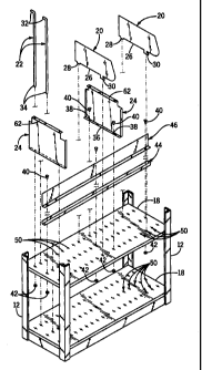
Referring to Figs. l and 2, a shelf assembly 10 constructed according to
the invention generally includes a series of corner posts 12 extending
upwardly from a
base 14 and interconnected at their upper ends with a top panel 16. A shelf 18
is
mounted above base 14, and a series of similarly configured shelves 18 are
engaged
with comer posts 12. The general construction of shelf assembly 10 is known in
the art,
and shelf assemblies of this type are available from Spacesaver Corporation of
Fort
Atkinson, Wisconsin, designated as four-post or case-type shelving. In a
manner as is
known, shelves 18 can be engaged with corner posts 12 at various locations, to
vary the
shelf height according to user requirements.
A variety of shelf accessories are adapted for use in combination with
shelf assembly 10. Such accessories include upright file dividers 20, rod-type
file
dividers 22, and bin dividers 24. Again; these types of shelf accessories aide
common
and well-known, and are representative of a variety of types of shelf
accessories which
can be used in combination with shelf assembly 10.
In a known manner, each upright file divider 20 includes a lower edge 26
engageable with the upwardly facing surface of shelf 18, a depending rear
retainer tab
28 and a depending front locking tab 30. Also in a known manner, each rod-type
file
divider 22 includes a bent upper retainer section 32 and a lower, axially
extending
mounting portion 34 which is coaxial with the area of rod-type file divider 22
between
4
CA 02366879 2006-03-09
retainer section 32 and mounting portion .34. Each bin divider 24wincludes a
lower
mounting flange 36 within which a pair of openings 38 are-formed. A pair of
fasteners
40, such as threaded screws, are adapted to extend through openings 38, and a
pair of
nuts 42 are engageable with fasteners 40. Other shelf accessories are
engageable with
$ shelves 18, such as a center support 44 adapted to secure sliding supports
or the like,
and/or a double entry center stop 46, which are engageable with a shelf 18 by
fasteners
such as 40 and nuts such as 42. Center support 44 and double entry center stop
46 are
representative of other types of shelf accessories which can be mounted to
shelf
assembly 10.
As shown in Figs. 1 and 2, each shelf 18 includes a series of slots or
openings 50 for use in mounting shelf accessories, such as upright file
dividers 20, rod-
type file dividers 22, bin dividers 24, center support 44 and center stop 46,
to each shelf
18. As shown, openings SO are formed in aligned rows in the upwardly facing
support
surface of each shelf 18, and openings 50 in each row are identically
configured. It is
understood, however, that various arrangements of openings 50 are contemplated
as
being within the scope of the present invention, and that openings 50 need not
necessarily be arranged in rows on shelves 18 and each opening need not have
the
configuration of openings 50. For example, openings 50 may be used in
combination
with conventional slot-type or circular-type openings, or may be formed such
that
openings 50 are arranged in one row but not all rows of openings in shelf 18.
Further,
the openings in shelves 18 may be formed such that only certain ones of the
openings
have the configuration of openings S0. In a manner to be explained, openings
50 are
configured so as to accommodate the different mounting arrangements for the
shelf
accessories described above, for mounting different shelf accessories to shelf
18 using
the same opening structure.
Figs. 3A and 3B illustrate the configuration of openings $0. Refernng to
Fig. 3A, each opening 50 includes a primary or central area or section 52 and
a pair of
secondary or end areas or sections 54 extending in opposite directions from
primary or
central area or section 52.
Each secondary area 54 is defined by a pair of parallel linear side edges 56
with an arcuate end edge 58 extending between and interconnecting the outer
ends of
CA 02366879 2006-03-09
side edges 56. The inner ends of secondary areas 54 face each other, and
primary area
52 is located between and interconnects the facing inner ends of secondary
areas 54.
Primary area 52 is defined by a pair of oppositely directed arcuate edges 60,
each of
which extends between one set of aligned secondary area side edges 56. With
this
construction, each secondary area 54 has a transverse dimension less than that
of
primary area 52.
Fig. 3B illustrates an alternative slot or opening 50', which has a
configuration like that of slot or opening 50 with the exception that end edge
58', which
extends between side edges 56', is squared off such that end edge 58' extends
perpendicularly to side edges 56' throughout a majority of the length of end
edge 58'. It
has been found that the configuration of slots or openings 5~ provides
somewhat less
stress on the tooling utilized to form opening SO than is the case with
opening SO'.
However, either opening configuration has been found to be satisfactory in
operation.
Opening 50 is shown with two secondary areas 54 extending in opposite
directions from primary area 52. It should be understood, however, that
opening 50
could be formed so that primary area 52 is closed at one end and only a single
one of
secondary areas 54 extends from primary area 52. In forming the opening in
this
manner, secondary area 54 would have a length slightly greater than that
illustrated with
respect to secondary areas 54 as shown.
In operation, openings 50 function to mount shelf accessories to shelves
18 in the following manner.
Referring to Fig. 4, bin divider 24 is placed between a pair of shelves 18
such that the lower mounting flange 36 of bin divider 24 engages the upwardly
facing
support surface of a lower one of shelves 18 and an upper mounting flange,
shown at 62,
is positioned adjacent the downwardly facing surface of an upper one of
shelves 18.
Flange openings 38 are positioned in alignment with selected openings 50 in
lower shelf
18, according to the desired position of bin divider 24. Similar openings in
upper
mounting flange 62 are positioned in alignment with matching ones of openings
50
formed in upper shelf 18. Screws 40 are then inserted through the flange
openings, such
as 38, and nuts 42 are engaged with the threaded shanks of screws 40.
Referring to Fig.
6, primary area 52 of opening 50 is sized and shaped so as to receive the
threaded shank
6
CA 02366879 2002-O1-07
' "' r
of screw 40, and secondary areas 54 have:a transverse dimensionless than that
of the
. . ,
shank of screw 40 so as to maintain screw 40 within primal area 52.
Referring to Fig. 5,-god-i'~pe shelf dividers 22-are engaged with upper and
lower shelves 18 in a similar manner. The upper portion of rod-type shelf
divider 22
extends through opening 50 formed in the upper shelf 18, and the lower
mounting
portion 34 of rod-type shelf divider 22 is received within opening SO in the
lower shelf
18. Rod-type shelf divider 22 has a diameter similar to that of the threaded
shank of
screw 40 with respect to Figs. 4 and 6, such that the diameter of rod-type
shelf divider
22 is greater than the width of opening secondary areas 54. In this manner,
the
mounting areas of rod-type shelf divider 22, such as mounting portion 34, are
maintained within the primary areas 52 of openings 50, to fik iod-type shelf
dividers 22
in position relative to shelves 18.
As shown in Figs. 7 and 8, upright shelf divider 20 is engageable with a
lower one of shelves 18 by positioning rear retainer tab 28 and front locking
tab 30 in a
selected aligned pair of openings 50, and at desired location along the length
of shelf 18.
Tabs 28, 30 are positioned in openings 50 such that tabs 28,30 extend into
both of
secondary areas 54 and through primary area 52. Divider 20 is then pulled
forwardly in
a conventional manner, such that the forward locking ear provided on locking
tab 30 is
positioned below the area of shelf 18 located forwardly of end edge 58 of the
forward
one of secondary areas 54, to lock shelf divider 20 to shelf 18 in a known
manner. As
shown in Fig. 8, a portion of tab 30 resides within the forward one of
secondary areas
54, and tab 30 extends across primary opening area 52 and into the rear one of
secondary opening areas 54. In this manner, tabs 28, 30 are positioned within
the
opening secondary areas 54, and the tolerances between the side surfaces of
tabs 28, 30
and the side edges 56 of secondary areas 54 are such as to maintain shelf
divider 20 in
an upright position, in a manner as is known.
It should be understood that one of secondary areas 54 could be
lengthened and the other secondary area 54 could be eliminated, and that tabs
28, 30
could be mounted to shelf 18 in the same manner as described previously while
providing adequate support for upright shelf divider 20. The lengthening of
one of
secondary areas 54 provides sufficient engagement with the side surfaces of
tabs 28, 30
7
CA 02366879 2002-O1-07
p
to support upright shelf divider 20, and the rear end portions of tabs 28, 30
simply
extend into primary area 52 or are wholly received within the elongated one of
secondary areas 54. - ' ~ --
It can thus be appreciated that the unique configuration of openings 50
enables shelving accessories with different types of mounting arrangements to
be
engaged with shelf 18, without modification to the mounting structure of the
shelf
accessory. Openings 50 are formed in place of conventional slot-type and hole-
type
openings, which are typically employed to mount shelving accessories with
different
types of mounting arrangements. The shelf manufacturer can thus reduce the
number of
tools required to form shelf openings, and can also reduce the number of
differently
configured products required to be manufactured. The distributors and users of
shelves
18 can stock a lesser number of shelves, and different shelf accessories can
be employed
without the need for changing out the shelves to mount the desired shelf
accessories.
Openings 50 are formed in a conventional manner, typically in a stamping
1 S process, when shelves 18 are being manufactured.
While shelves 18 are illustrated as being of the formed sheet metal type, it
is understood that the configuration of openings 50 could be employed in any
type of
shelf made of any satisfactory type of shelf material so as to accommodate
different
mounting arrangements for different types of shelf accessories.
Various alternatives and embodiments are contemplated as being within
the scope of the following claims particularly pointing out and distinctly
claiming the
subject matter regarded as the invention.
8