Language selection

Search

Patent 2366886 Summary

Third-party information liability

Some of the information on this Web page has been provided by external sources. The Government of Canada is not responsible for the accuracy, reliability or currency of the information supplied by external sources. Users wishing to rely upon this information should consult directly with the source of the information. Content provided by external sources is not subject to official languages, privacy and accessibility requirements.

Claims and Abstract availability

Any discrepancies in the text and image of the Claims and Abstract are due to differing posting times. Text of the Claims and Abstract are posted:

  • At the time the application is open to public inspection;
  • At the time of issue of the patent (grant).
(12) Patent: (11) CA 2366886
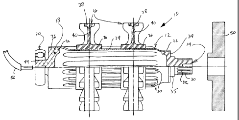
(54) English Title: SNOWMOBILE DRIVE SHAFT
(54) French Title: ARBRE D'ENTRAINEMENT DE MOTONEIGE
Status: Deemed expired
Bibliographic Data
(51) International Patent Classification (IPC):
  • F16C 3/02 (2006.01)
(72) Inventors :
  • FERRIMAN, LARRY J. (Canada)
  • CONNELLY, PETER J. (Canada)
  • CLELAND, TERRY P. (Canada)
(73) Owners :
  • LITENS AUTOMOTIVE (Canada)
(71) Applicants :
  • LITENS AUTOMOTIVE (Canada)
(74) Agent: IMAI, JEFFREY T.
(74) Associate agent:
(45) Issued: 2008-07-22
(22) Filed Date: 2002-01-07
(41) Open to Public Inspection: 2002-07-08
Examination requested: 2003-12-10
Availability of licence: N/A
(25) Language of filing: English

Patent Cooperation Treaty (PCT): No

(30) Application Priority Data:
Application No. Country/Territory Date
60/260,322 United States of America 2001-01-08

Abstracts

English Abstract

A driveshaft for a snowmobile has an elongated hollow tube having a longitudinal extent. The tube has a series of circumferentially spaced longitudinally extending splines. Both ends of the tube each have an insert for journal mounting the tube. At least two sprockets are mounted on the tube in a spaced relation. Each of the sprockets has an inner hub which has an inner circumferential surface contoured to complementarily engage with the tube in a frictional fit.


French Abstract

L'invention porte sur un arbre d'entraînement pour motoneige possédant un long tube creux pourvu d'un prolongement longitudinal. Le tube compte une série de cannelures d'extension espacées sur la circonférence du tube. Les deux extrémités du tube sont pourvues d'un raccord permettant de fixer le tube à un tourillon. Au moins deux roues dentées sont installées sur le tube, selon un espacement donné. Chacune de ces roues dentées possède un moyeu intérieur don't la surface circonférentielle intérieure est conçue pour recevoir le tube de sorte à obtenir une mise en place par frottement.

Claims

Note: Claims are shown in the official language in which they were submitted.


What is claimed:


1. A driveshaft for a snowmobile comprising:
an elongated hollow tube having a longitudinal extent and having a series of
circumferentially spaced longitudinally extending splines,
said tube having a first end having a driving insert for journal mounting said
first end,
said tube having a second end having a driven insert for journal mounting said
second
end, and
a pair of sprockets mounted on said tube in a spaced relation, each of said
sprockets
having an inner hub having an inner circumferential surface contoured to
complementarily
engage with said longitudinally extending splines of said tube in a frictional
fit.

2. A drive shaft according to claim 1 wherein said first end has a first
diameter, said
second end having a second diameter and said splines are formed on a middle
section
extending between said first and second ends, said middle section having a
third diameter,
said first diameter being less than said third diameter.

3. A drive shaft according to claim 2 wherein said third diameter is less than
said second
diameter.

4. A drive shaft according to claims 1 or 3 wherein each of said sprockets is
press fitted
onto said splines of said tube.

5. A drive shaft according to claims 1 or 4 wherein said tube is a high
strength low alloy
steel.

6. A drive shaft according to claims 1 or 5 wherein said sprockets are a
molded ultra
high molecular weight polyethylene.

7. A drive shaft according to claim 6 wherein said tube has an outside
diameter of about
3 inches.

8. A drive shaft according to claim 7 wherein said tube has a wall thickness
of about
0.065 inches.


2. A drive shaft according to claim 1 wherein said first end has a first
diameter said
second end having a second diameter and said splines are formed on a middle
section
extending between said first and second ends, said middle section having a
third
diameter, said first diameter being less than said third diameter.

3. A drive shaft according to claim 2 wherein said [middle section extends
between
said first and second ends] third diameter is less than said second diameter.

4. A drive shaft according to claims 1 or 3 wherein each of said sprockets is
press
fitted onto said splines of said tube.

5. A drive shaft according to claims 1 or 4 wherein said tube is a high
strength low
alloy steel.

6. A drive shaft according to claims 1 or 5 wherein said sprockets are a
molded ultra
high molecular weight polyethylene.

9. A drive shaft according to claims 1 or 2 wherein said driving insert is
configured
to receive a driving assembly.


9. A drive shaft according to claims 1 or 2 wherein said driving insert is
configured to
receive a driving assembly.

10. A drive shaft according to claim 9 wherein said driving insert is press
fitted and
welded to said tube.

11. A drive shaft according to claim 9 wherein said driven insert is
configured to
operative engage a driven assembly.

12. A drive shaft according to claim 11 wherein said driven insert is press
fitted to said
tube

13. A drive shaft according to claim 11 wherein said driving insert is press
fitted and
welded to said tube.

14. A drive shaft according to claim 11 wherein said driven assembly is a
speedometer.
15. A drive shaft according to claim 11 wherein said driven assembly is a disc
of a disc
brake assembly.

Description

Note: Descriptions are shown in the official language in which they were submitted.


CA 02366886 2002-01-07

SNOWMOBILE DRIVESHAFT
Field of Invention
[001] This invention relates to a driveshaft for a snowmobile. In particular,
this invention
relates to a driveshaft having improved torque transfer characteristics and
reduced weight.
Background of Invention
[002] Snowmobiles are becoming increasingly popular. Examples of known
snowmobiles are described in United States patent nos. 4,987,965; 5,660,245;
5,667,031;
and 5,904,217. The increasing popularity of snowmobiles increases competition
between
manufacturers. As a result, snowmobiles manufacturers have been increasing the
horsepower of the engines which increases the top speed of the vehicles in
order to make
the vehicles more marketable.

[003] Typically, a snowmobile has a drive track positioned beneath a frame
assembly. A
transmission is provided to receive power from the engine. The power is then
transferred
to the drive track via a rotatably mounted driveshaft. A pair of sprockets is
mounted on the
driveshaft in order to transfer power to the drive track.

[004] Heretofore, driveshaffts for snowmobiles have been made from solid hot
rolled steel
bar stock. The bar stock has a hexagonal cross section. The sprockets are then
mounted on
the bar stock and fixed thereon.

[005] Current driveshafts are able to effectively transfer power to the track.
However,
current driveshafts are also subjected to shock loading especially when the
snowmobile
travels over rough terrain at high rates of speed. The shock loads cause shaft
bending
which damages the supporting bearing housings and destroys the shaft to
sprocket
interface. Current driveshafts are able to sustain at most 50 repetitive shock
loads of 1500
ft-lbs before the driveshaft or bearing is permanently deformed or damaged.

[006] Thus, there exist a need in the production of snowmobiles for a
driveshaft capable
of transferring increasingly amounts of torque, having a reduced weight, while
being
capable of withstanding severe shock loads without significant deformation.

1


CA 02366886 2002-01-07
Summary of Invention
[007] The disadvantages of the prior art may be overcome by providing a hollow
driveshaft having a series of longitudinally extending splines which
frictionally receives a
pair of sprockets.

[008] It is desirable to provide a hollow driveshaft having an increased
diameter to
improve bending stiffness and reduce stress therein.

[009] According to one aspect of the invention, there is provided a driveshaft
for a
snowmobile that has an elongated hollow tube having a longitudinal extent. The
tube has a
series of circumferentially spaced longitudinally extending splines. Both ends
of the tube
each have an insert for journal mounting the tube. Sprockets are mounted on
the tube in a
spaced relation. Each of the sprockets has an inner hub which has an inner
circumferential
surface contoured to complementarily engage with the tube in a frictional fit.
Description of the Drawings
[010] In drawing which illustrate embodiment of the present invention,
Figure 1 is a partial cross section of the preferred embodiment of the present
invention.

Description of the Invention
[011] Refemng to Figure 1, a driveshaf3 10 of the present invention is
generally
illustrated. Driveshaft 10 generally comprises a tube 12, a chain or driving
insert 14, a pair
of sprockets 16, a speedometer or driven insert 18 and a bearing 20. The
driveshaft 10 has
a longitudinal extent that corresponds to the transverse direction of the
snowmobile in
which the driveshaft 10 is installed.

[012] Tube 12 is generally elongate and has a first end 22 having a first
diameter, a
middle section 24 and a second end 26 having a second diameter. Preferably,
first diameter
is less than the second diameter.

[013] In the preferred embodiment, tube 12 is a steel tube of high strength
low alloy steel,
having about a 3 inch outside diameter and a wall thickness of about 0.065
inches. The
preferred embodiment surprisingly provides a 400% improvement in bending
stiffness, as

2


CA 02366886 2002-01-07

well as a reduced weight and inertia in comparison with a conventional hex
type shaft of
the prior art.

[014] The first end 22 is drawn to reduce the diameter of the tube 12 to the
first diameter
relative to a third diameter of the middle section 24. The reduced diameter
enables the
sprockets 16 to be mounted on the middle section 24.

[015] Middle section 24 has a series of longitudinally extending parallel
splines 30 that
are spaced about the circumferential extent of the tube 12. Splines 30 are
formed using
conventional methods after the first end is drawn to the reduced diameter.
Splines 30
extend from the first end 22 presenting an entry for the sprockets 16.

[016] Chain insert 14 has a series of splines 32 and stepped end 34. Stepped
end 34 is
sized to frictionally engage within the inside diameter of fu-st end 22 and
welded thereto.
Shoulder 35 can be used to seal the driveshaft 10. Stepped end 34 journal
mounts the
driveshaft 10. A driving assembly 50 such as a gear is mounted on the chain
insert 14 on
splines 32. Torque is applied through the driving assembly 50 to the chain
insert 14 that
transmits the torque to the tube 12.

[017] Sprockets 16 each has an inner hub 36, an outer hub 38 and an
interconnecting web
40. The inner hub 36 has an inner circumferential surface having a series of
axially
extending ribs which complementarily engage with splines 30 in a frictional or
interference
fit. The outer hub 38 can be of any suitable configuration depending upon the
type of track
used by the particular manufacturer. Preferably, sprockets 16 are molded ultra
high
molecular weight polyethelene.

[018] Each of the sprockets 16 is mounted on the tube 12 by inserting the
first end 22 of
the tube 12 through the hub 36. Once the sprocket 16 is in the desired
location along the
tube 12, the sprocket 16 is then fixed in place by any suitable methods,
including press

fitting.

[019] Speedometer insert 18 has a stepped configuration. A portion 42
frictionally fits
within the inside diameter of second end 26 of tube 12. A shaft portion 44 is
press fitted to
the bearing 20 that rotatingly supports the second end 26. The shafft portion
44 is provided
3


CA 02366886 2002-01-07

with a non-circular bore in the end thereof. The bore receives a cable of a
driven assembly
52 that is operably connected with a speedometer.

[020] Preferably, chain insert 14 is forged and machined from steel that is
compatible for
welding to the tube 12. The speedometer insert 18 is preferably die cast
aluminum.

[021] Optionally, shafft portion 44 can be extended allowing other driven
assemblies or
components to be mounted thereon. For example, a disc can be mounted on the
shaft
portion 44. The disc cooperates with a set of calipers providing a braking
function. In
1o applications requiring torque transfers, the speedometer insert 18 is
preferably welded in
place, in addition to being press fitted into the second end 26 of the tube
12.

[022] One common failure of prior art hex shafts is damage at the sprocket to
shaft
interface. Failures commonly occur when the sprocket is subjected to about 400
ft-lbs.
However, the preferred embodiment of the present invention has shown to be
capable of
transferring torques in excess of 1800 ft-lbs.

[023] Although the invention has been described with reference to certain
specific
embodiments, various modifications thereof will be apparent to those skilled
in the art
without departing from the scope of the invention as defined by the attached
claims.

[024] In particular, the preferred method of forming the splines 32 on the
middle section
24 utilizes a mandrel to support the tube 12. The second end 26 has a larger
diameter than
the first end 22 and the middle section 24. The larger second diameter enables
the mandrel
to be removed from within the tube 12 after formation of the splines 32. It is
now apparent
to those skilled in the art that the second end 26 could be further processed,
for example by
a swaging process, to subsequently reduce the diameter of the second end 26.

4

Representative Drawing
A single figure which represents the drawing illustrating the invention.
Administrative Status

For a clearer understanding of the status of the application/patent presented on this page, the site Disclaimer , as well as the definitions for Patent , Administrative Status , Maintenance Fee  and Payment History  should be consulted.

Administrative Status

Title Date
Forecasted Issue Date 2008-07-22
(22) Filed 2002-01-07
(41) Open to Public Inspection 2002-07-08
Examination Requested 2003-12-10
(45) Issued 2008-07-22
Deemed Expired 2017-01-09

Abandonment History

There is no abandonment history.

Payment History

Fee Type Anniversary Year Due Date Amount Paid Paid Date
Application Fee $300.00 2002-01-07
Registration of a document - section 124 $100.00 2002-07-08
Request for Examination $400.00 2003-12-10
Maintenance Fee - Application - New Act 2 2004-01-07 $100.00 2003-12-22
Maintenance Fee - Application - New Act 3 2005-01-07 $100.00 2004-12-23
Maintenance Fee - Application - New Act 4 2006-01-09 $100.00 2005-12-20
Maintenance Fee - Application - New Act 5 2007-01-08 $200.00 2006-12-20
Maintenance Fee - Application - New Act 6 2008-01-07 $200.00 2007-12-21
Final Fee $300.00 2008-04-30
Maintenance Fee - Patent - New Act 7 2009-01-07 $200.00 2008-12-12
Maintenance Fee - Patent - New Act 8 2010-01-07 $200.00 2009-12-11
Maintenance Fee - Patent - New Act 9 2011-01-07 $200.00 2010-12-17
Maintenance Fee - Patent - New Act 10 2012-01-09 $250.00 2011-12-13
Maintenance Fee - Patent - New Act 11 2013-01-07 $250.00 2012-12-13
Maintenance Fee - Patent - New Act 12 2014-01-07 $250.00 2013-12-24
Maintenance Fee - Patent - New Act 13 2015-01-07 $250.00 2014-12-17
Owners on Record

Note: Records showing the ownership history in alphabetical order.

Current Owners on Record
LITENS AUTOMOTIVE
Past Owners on Record
CLELAND, TERRY P.
CONNELLY, PETER J.
FERRIMAN, LARRY J.
Past Owners that do not appear in the "Owners on Record" listing will appear in other documentation within the application.
Documents

To view selected files, please enter reCAPTCHA code :


To view images, click a link in the Document Description column. To download the documents, select one or more checkboxes in the first column and then click the "Download Selected in PDF format (Zip Archive)" or the "Download Selected as Single PDF" button.

List of published and non-published patent-specific documents on the CPD .

If you have any difficulty accessing content, you can call the Client Service Centre at 1-866-997-1936 or send them an e-mail at CIPO Client Service Centre.


Document
Description 
Date
(yyyy-mm-dd) 
Number of pages   Size of Image (KB) 
Representative Drawing 2002-02-28 1 18
Abstract 2002-01-07 1 14
Description 2002-01-07 4 209
Drawings 2002-01-07 1 31
Claims 2002-01-07 2 58
Cover Page 2002-07-05 1 43
Representative Drawing 2008-07-07 1 18
Cover Page 2008-07-07 1 44
Claims 2007-12-14 3 102
Correspondence 2002-02-05 1 23
Assignment 2002-01-07 2 79
Assignment 2002-07-08 3 116
Prosecution-Amendment 2003-12-10 1 24
Prosecution-Amendment 2007-06-19 2 41
Prosecution-Amendment 2004-05-20 1 26
Prosecution-Amendment 2007-12-17 4 138
Correspondence 2008-04-30 1 26