Note: Descriptions are shown in the official language in which they were submitted.
CA 02366968 2001-10-05
WO 00/61986 PCT/CAOO/00372
TITLE OF THE INVENTION
AUTOMATIC DRY RELEASE CONNECTOR
FIELD OF THE INVENTION
This invention relates to a fluid conduit coupling device which
allows the simultaneous coupling or uncoupling of pairs of fluid conduits
substantially without the loss of process fluid or the introduction of air or
ambient fluid, and which will automatically uncouple with the application of a
predetermined tensile force.
BACKGROUND Of THE INVENTION
It is desirable to have a means of coupling and uncoupling fluid
conduits such as hoses without the need to drain the hoses prior to coupling
or
risk fluid loss. Moreover, it is desirable to have a means to couple fluid
conduits
without introducing contaminants such as ambient fluids and air into the
process fluid. In situations where it is foreseeable that it might be
necessary to
uncouple the fluid conduits very quickly, or under other circumstances
preventing the use of a manually actuated release, it is desirable to have a
means of disconnecting the fluid conduits by the application of a predefined
amount of tensile force on the fluid conduits, preferably without damage to
the
conduits or the coupling, and in a manner allowing rapid recoupling without
the
need for prior repair. Such decoupling should occur without fluid leakage from
the conduits.
Such quick-connect / quick disconnect dry-break connectors are
especially desirable for use with liquid-circulating personal temperature
maintenance systems, particularly when such devices are used by those
piloting or driving vehicles from which rapid ejection, possibly followed by
reconnection, may become necessary.
CA 02366968 2001-10-05
WO 00/61986 PCT/CA00/00372
-2-
Numerous detachable fluid conduit coupling systems are known in
the prior art. Many such devices employ spring-loaded ball-type valves which
may reduce the loss of process fluid upon uncoupling. Such systems are
described in United States Patent 4,105,046 of Sturgis, and United States
Patent 5,092,364 of Mullins, both of which describe detachable fluid
couplings.
However, systems of this type fail to provide a means to substantially prevent
the introduction of contaminants such as air and ambient fluids into the
process
fluid upon coupling. This is because the spring-loaded ball type valves lack a
means to expel potentially contaminating materials from the valve surfaces
prior
to joining.
United States Patent 4,794,937 of Hoffman describes a plug and
socket-type plug coupling designed for application in high pressure systems.
The design of this coupling necessitates the use of gaskets recessed within
the
coupling apparatus and does not provide a means of expelling ambient fluids or
air prior to coupling.
Most fluid coupling systems are not adapted to allow damage-free
separation of the connector ends upon the application of tensile force when a
manual release mechanism has not been actuated. This can result in the loss
of significant quantities of process fluid due to conduit rupturing when
emergency separation becomes necessary. In situations where the process
fluid is potentially dangerous, this can pose a substantial hazard. Moreover,
should separation not occur under conditions where it is necessary the device
through which fluid was being circulated may be dragged behind or into the
fluid
source device, resulting in injury and property damage.
United States Patent 5,529,085 of Richards et al teaches a
breakaway hose coupling designed to limit the loss of process fluid upon the
separation of the coupling. This design relies on the breakage of shear pins
to
effect release of the coupled hoses. Thus, while an emergency release system
is provided, it is not a quick-connect / quick release system. Moreover,
design
is not adapted to exclude ambient fluid and air upon hose coupling.
The most common commercially available fluid quick-connector
CA 02366968 2007-10-31
74698-61
- 3 -
types known to the inventors are those produced by Colder
Products Company of Minnesota, U.S.A. Features of these
connectors are detailed in United States Patent
Numbers: 4,436,125, 4,541,457, 4,911,655, 5,033,777,
5,052,725, 5,104,158, 5,126,041, 5,494,074, 5,845,943, and
D357,307 and D384,712. Some connectors manufactured by
Colder Products Company purport to have self-sealing valves.
However, due to design factors, a substantial amount of
process fluid is typically lost when these valves are
uncoupled, and a substantial amount of ambient fluid or air
is introduced into the process fluid upon coupling.
Moreover, no Colder Products Company valve is known to the
inventors which uncouples automatically upon the application
of a predetermined tensile force.
U.S. Patent 2,538,259 describes a breakaway
bracket for anchoring a fluid coupler to a relatively fixed
object such as a tractor. The bracket requires the presence
of the fixed object for operation. No means is provided for
expelling ambient fluids or air during coupling.
SUMMARY OF THE INVENTION
It is thus an object of embodiments of the present
invention to provide a fluid conduit coupling apparatus
which allows quick connection and disconnection with
substantially no introduction of ambient fluids or air into
the process fluid.
According to one aspect of the invention, there is
provided a fluid conduit coupling comprising: first and
second flow channel assemblies, the first assembly having a
first flow channel therethrough and said second assembly
having a second flow channel therethrough, and each assembly
having a first end for attaching to a fluid conduit and each
having a second end, said second ends of said first and
CA 02366968 2007-10-31
74698-61
- 4 -
second assemblies configured to mate with each other by
relative axial movement; said first assembly having therein
first closure means moveable in said first channel between a
first position in which said first channel is closed off and
a second position in which said first channel is open, and
means for biasing said closure means toward its first
position, said closure means having a leading surface toward
an end of said first channel at the second end of said first
assembly; said second channel having an end portion at the
second end of said second assembly, said end portion being
insertable in the second end of said first channel, and
having a leading surface for engaging the leading surface of
said first closure means to move said first closure means
towards its second position when said assemblies are moved
axially towards each other, said leading surfaces being
complementary for forcing fluid from between them when the
surfaces are brought into mutual engagement, said second
assembly including second closure means moveable between a
first position in which the end portion of said second
channel is closed off and a second position in which the end
portion of said second channel is open to allow fluid
communication between said first and second channels when
said end portion is inserted into said first channel, and
means for biasing said second closure means towards its
first position; said first assembly having means for moving
said second closure means to its second position when said
assemblies are brought together; quick connect/disconnect
means for securing said assemblies together, and engaged by
mating said assemblies together and releasable by means of a
predetermined tensile force or by a mechanical latch; a wall
of said first channel including sealing means for forming a
seal about said first closure means to close said first flow
channel when said first closure means is in its first
position, said first closure means and the wall of said
CA 02366968 2007-10-31
74698-61
- 5 -
first channel forming a gap therebetween for the passage of
fluid through said gap and beyond the leading surface of
said first closure means when said first closure means is
moved to its second position to open said first flow
channel, disengagement of said first closure means from said
sealing means being required to open said first flow
channel, wherein said sealing means is configured to
sealingly engage said end portion of the second channel at
the second end of said second assembly as said first closure
means is moved from its first position towards its second
position and to maintain sealing contact with said end
portion as said first closure means is moved from its first
position and said end portion at the end of said second
assembly is moved axially into said first channel connecting
said first channel to said second channel.
In another aspect of the invention there is
provided a quick connect/disconnect coupling for a fluid
conduit, the coupling comprising assemblies for attaching to
the ends of a conduit to be connected and for subsequently
mating together, each assembly comprising a normally closed
channel; means for expelling fluid from between the
assemblies when the assemblies are to be connected to each
other; means for preventing fluid from entering the
assemblies from outside when the assemblies are being
connected; means for opening the normally closed channels,
means operable by the connecting of the assemblies to each
other; latch means for securing the assemblies together, the
latch means disconnectable by means of a hand operated
unlatching means or by the application of a predetermined
tensile force.
CA 02366968 2007-10-31
74698-61
- 5a -
BRIEF DESCRIPTION OF THE DRAWINGS
Embodiments of the invention will now be described
by way of non-limiting examples, and with reference to the
drawings in which:-
FIGURE 1 is a top view of a coupler according to
an embodiment of the invention, in a disconnected state;
FIGURE 2 is a side view of the coupler of
Figure 1;
FIGURE 3 is an end view of the coupler of
Figure 1, illustrating the two ends of the coupler which are
juxtaposed in Figure 2;
FIGURE 4 is a cross-sectional top view of the
coupler of Figure 1 in a completely disconnected state;
FIGURE 5 is a cross-sectional top view of the
coupler of Figure 1 in a partially disconnected state;
FIGURE 6 is a cross-sectional top view of the
coupler of Figure 1 in a completely connected state;
FIGURE 7 is a cross-sectional side view of the
coupler of Figure 1 showing a preferred latch assembly in a
completely uncoupled state;
FIGURE 8 is a cross-sectional side view of the
coupler of Figure 7 showing the latch assembly in an
intermediate state just prior to complete coupling or
complete uncouplings;
FIGURE 9 is a cross-sectional side view of the
coupler of Figure 7 showing the latch assembly in its
completely coupled state;
CA 02366968 2007-10-31
74698-61
- Sb -
FIGURE 10 is a cross-sectional side view of the
coupler of Figure 7 showing the latch assembly in an
intermediate state immediately prior to uncoupling using the
manual release button; and
FIGURE 11 is a cross-sectional side view of the
coupler of Figure 1 showing the securing device in a
completely coupled state experiencing a moderate tensile
force;
FIGURE 12 is a cross-sectional side view of the
coupler of Figure 1 showing the latch assembly in an
intermediate state immediately preceding complete automatic
uncoupling;
FIGURE 13 is an exploded perspective view of two
halves of a coupler according to Figure 1.
DETAILED DESCRIPTION OF THE PREFERRED EMBODIMENTS
In the following description, similar features in
the drawings have been given similar reference numerals.
The drawings illustrate a double or twin coupling for
connecting together two pairs of conduits or for inserting
at an intermediate point in a pair of conduits. It should
be noted that the coupling can equally be constructed for
use as a single coupling in a single conduit. In that case
one flow passage or channel is either not present or not
used. The coupling can also be constructed as a multiple
coupling for a group of conduits.
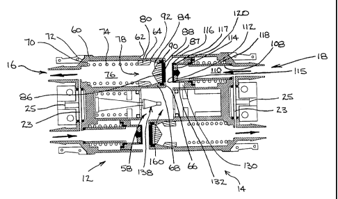
With reference to Figures 1 to 3, there is
illustrated one form of the coupler according to an
embodiment of the invention. Thus, the coupler 10 comprises
first and second parts 12 and 14 respectively which are
CA 02366968 2007-10-31
74698-61
- Sc -
configured to meet together, as will be discussed, and as
illustrated in cross section in Figure 6.
Each of parts 12 and 14 are provided with flow
passage or channel assemblies 16, 18, 20 and 22. The
channels provide flow passages through parts 12 and 14 but
the flow is interruptible, as will be discussed.
Each of parts 12 and 14 may include a bypass
channel 23, a primary purpose of which is to allow some
circulation for maintenance of temperature uniformity in the
system. Where not necessary, the bypass channels may simply
be blocked or omitted. Where the coupling is constructed
for use in a single conduit, no bypass will be present.
Hose barbs 24, 26, 28 and 30 provide for the
securing of respective conduit ends to parts 12 and 14.
Tail clamps 32 and 34, consisting of identical parts 36 and
38, and 40 and 42, respectively, are secured together by
means of fasteners such as screw pairs 44 and 46 to securely
clamp the conduit ends to the hose barbs. In applications
where safety precludes the use of screws, pins or rivets may
be used.
CA 02366968 2001-10-05
WO 00/61986 PCT/CAOO/00372
-6-
The tail clamps serve not only to secure the conduits to the
coupling but may also to relieve strain as between the conduits and the
channel
assemblies, to provide a protective shield over bypasses 23, and to provide a
thermal and/or pressure sensor receptacle through the thermal well 25.
Part 12 includes the latch pin 138 which, upon connecting together
parts 12 and 14 of coupler 10, is inserted into a receptacle assembly 160
(refer
to Figure 7) which contains a latch plate 164. As will be described later, the
latch pin 138 locks with the latch plate 164 to secure a coupler in a
connected
state.
io The part 14 includes a manual release assembly 54 which, on
application of pressure to the release button 56 causes the latch pin 138 to
unlock from latch plate 164.
Figures 4 to 6 illustrate the flow channel assemblies in detail. As
with all of the series of figures, the coupler is shown in a double
configuration
is for insertion between two pairs of conduit ends. More particularly, the
figures
illustrate a form of the coupler which is preferably used as part of a supply
and
return system, whereby a fluid supply flows in one direction through one side
of
the coupler and in the opposite direction to the other side of the coupler.
Thus,
Figures 4 to 6 illustrate direction of flow by means of the arrows.
Furthermore,
20 the figures progressively illustrate the coupler in a disconnected state in
Figure
4, a partially connected state in Figure 5, and a connected state in Figure 6.
The parts 12 and 14 of coupler 10 are the same insofar as the
channel assemblies are concerned, and differ only in latch assembly 58, in
that
part 12 includes latch pin 138 and associated parts, and part 14 includes
25 receptacle assembly 160. Since the two flow channels through the coupler
are
the same, it is necessary to describe in detail one side only.
Thus, channel assembly 16 in part 12 comprises a channel wall 60
which houses the assembly components. Channel wall 60 is stepped on the
outside thereof at 62 to provide a length 64 of decreased outside diameter
30 extending to the end 66 of wall 60.
The inside of wall 60 is profiled to provide a part 68 of decreased
CA 02366968 2001-10-05
WO 00/61986 PCT/CAOO/00372
-7-
inside diameter.
Channel wall 60 is also stepped internally to provide a shoulder 70
adjacent end 72 of channel wall 60.
A coil spring 74 is seated within channel 76 against shoulder 70.
Closure means comprising a shuttle 78 (refer to Figure 13)
comprises a base ring 80, a series of struts 82 and a plug 84. Plug 84
includes
a leading surface 86.
A sealing ring 88 is disposed around plug 84, and a complimentary
sealing ring 90 is fitted within area 68 of channel wall 60.
In the preferred configuration the leading surface 86 is overlaid by
an elastomeric cap comprising a face seal 87 and integral sealing ring 88.
In the normal disconnected position of the coupling, as illustrated in
Figure 4, shuttle 78 is biased by spring 74 to close off the opened end of the
channel. In that condition the sealing rings 88 and 90 combine to prevent
fluid
leakage. The face seal 87 of shuttle 78 is substantially flush with the end 66
of
channel wall 60 and is held in that position by the abutment of base ring 80
against the narrowing interior of channel wall 60 at 92.
The shuttle 78 is free to move within the channel wall 60 against
the force of spring 74 when sufficient force is applied to the leading surface
86
of shuttle 78.
Turning to the complimentary part 14, the channel wall 94 has an
inside diameter at end 96 which is matched to the outside diameter of channel
wall 60 of part 12 at area 64.
Toward opposite end 98 of channel wall 94 the wall is stepped to
form shoulders 100 and 102. A side vent tube 104 (refer to Figure 13) is
seated
against shoulder 102 and fixed to channel wall 94. Seal 106 provides sealing
as between tube 104 and shoulder 102 of channel wall 94. Seal 106 may be
omitted where side vent tube 104 is welded directly to shoulder 102.
Side vent tube 104 consists of lower tubular part 108 which actually
defines within it a part of channel 110. From the end of tubular part 108, a
group of struts 111 support plugs 112. The struts 111 are preferably extended
CA 02366968 2001-10-05
WO 00/61986 PCT/CAOO/00372
-8-
along the length of tubular part 108 to form reinforcing ribs. Plug 112
includes a
leading surface 114, a peripheral seal 116 and a sealing ring 117. Preferably
the leading surface 114 is flush with the end 96 of channel wall 94.
In the preferred configuration, the leading surface 114 is overlaid by
an elastomeric cap which forms a face seal 115 integral with peripheral seal
ring 116 and sealing ring 117. The plug 112 preferably includes a shoulder 113
into which sealing ring 117 is molded.
A coil spring 118 is disposed about tubular part 108 and seated
against shoulder 100 of channel wall 94.
To complete the closure means in the channel assembly 18, an
annular slider 120 is disposed about side vent tube 104 and is freely slidable
in
the annulus 122 between the channel wall 94 and the tubular part 108. Slider
120 is provided with a sealing surface 124 at one end and a sealing ring 126
at
the other end. Slider 120 also includes a shoulder 128 which seats against
spring 118. When the channel 110 is in the normally closed position when the
parts 12 and 14 are disconnected, as illustrated in Figure 4, slider 120 is
biased
by spring 118 to a position where sealing surface 124 seals against sealing
ring
117 of plug 112, and sealing ring 126 seals against tubular part 108 to
thereby
prevent leakage into or out of channel 110.
Axial force exerted against the slider 120 will permit the slider to
move against the biasing force of spring 118.
Without considering for the moment the latch assemblies 58, the
operation of the channel assemblies will be described with reference to the
three positions illustrated in Figures 4 to 6. Figure 4 illustrates the
coupler in a
disconnected state in which the springs 74 and 118 respectively bias the
shuttle
78 and the slider 120 into positions in which the channels are closed to the
outside, so that no leakage can occur either inwardly or outwardly.
When the two parts 12 and 14 are moved together axially as
illustrated in Figure 5, the first contact will be between the leading
surfaces 86
and 114 of shuttle 78 and side vent tube 104 respectively. When this contact
is
made, any ambient fluid, whether liquid or atmospheric air, will be
substantially
CA 02366968 2001-10-05
WO 00/61986 PCT/CAOO/00372
-9-
expelled from the area between the surfaces.
As parts 12 and 14 are further overlapped by additional axially
movement, the end 66 of channel wall 60 moves into the annular space 130
between channel wall 94 and the leading land 132 of slider 120. At the same
time, plug 112 is forcing shuttle 78 into channel 76 against the bias of
spring 74,
resulting in sealing ring 90 in channel wall 60 to be first transferred to
peripheral
seal 116 of plug 112 and then to engagement with the leading land 132 of
slider
120. The movement of the shuttle thus opens a flow path between struts 82 of
shuttle 78 and the wall 60. However during this motion the channels 76 and
110 are effectively sealed against inward or outward leakage at their
interface
by the sealing rings 90, 117 and 126.
As further axial movement occurs, the end 66 of channel wall 60
abuts against shoulder 134 of slider 120. As parts 12 and 14 are forced into
the
connected state, the end 66 of channel wall 60 forces slider 120 to move
against the bias of spring 118. This movement of slider 120 opens the flow
path between the struts 111 of side vent tube 104, so that fluid can begin to
flow through the side vents. This thus opens flow between channels 76 and
110 and effectively seals against inward and outward leakage to the ambient.
At the same time, the shuttle 78 remains restrained by leading surface 114 of
plug 112 and is moved further within channel wall 60 against the force of
spring
74.
As is clear from Figure 6, a flow path is also opened around the
outside of plug 84 and plug 112 of shuttle 78 and side vent tube 104
respectively.
When fully coupled, end 96 of channel wall 94 abuts shoulder 62 of
channel wall 60.
The coupler has thus been connected in a way which prevents
leakage either into or out of the unit.
In disconnecting, the process is simply reversed, so that shuttle 78
and slider 120 are caused by springs 74 and 118 respectively to return to
their
initial positions to close off the channels to again prevent leakage in the
CA 02366968 2001-10-05
WO 00/61986 PCT/CAOO/00372
-10-
disconnect step.
Turning to Figures 7 to 12, the latch assemblies 58 are illustrated in
detail.
The pin assembly 136 comprises latch pin 138 having a base plate
140. A spring 142 is disposed around latch pin 138 and is seated against base
plate 140. Spring 142 is held under compression by spring retainer 144. Thus
spring 142 maintains a constant bias against base plate 140.
Base plate 140 and latch pin 138 are together siidable within the
latch pin housing 146. However, the extent of sliding movement of base plate
140 is limited on one side of housing 146 by plate 148. Plate 148 thus acts as
a stop for one side of base plate 140.
Latch pin 138 includes a shoulder 150 which is preferably formed
by positioning a cone-shaped part 152 on latch pin 138. Latch pin 152 is then
extended at 154 beyond the end of cone-shaped part 152.
As is evident from the drawings, the forward area of the latch pin
138, particularly including the shoulder 150 extends beyond the end 158 of
latch pin housing 146.
Turning to receptacle assembly 160, the receptacle housing 162
includes a latch plate or striker plate 164 which extends down into the
interior of
housing 162.
A manual release button 56, disposed on the outside of receptacle
housing 162, has fixed thereto a manual release pin 168. Button 56 is biased
toward the upward position shown in Figures 7 to 9 and 11 to 12 in which the
manual release pin 168 may be said to be in a rest position.
The outer part 170 of spring retainer 144 and the latch plate 164
leave openings 172 and 174 at the entries to latch pin housing 146 and
receptacle housing 162 respectively. Openings 172 and 174 are configured
such that latch pin 138 can be tilted relative to the axis of the housings.
The spring retainer 144 and latch plate 164 are secured in position
by shear pins 176 and 178, and 180 and 182 respectively.
The operation of the latch assembly 58 is illustrated sequentially in
CA 02366968 2001-10-05
WO 00/61986 PCT/CAOO/00372
-11-
Figures 7 to 12. Those figures illustrate both manual and automatic
disconnection and also illustrate a safety feature provided by the shear pins.
When the parts 12 and 14 of coupler 10 are brought together, latch
pin 138 extends out of the opening 172 in latch pin housing 146 and through
the opening 174 in receptacle housing 162. As the parts are moved more
closely together, as illustrated in Figure 8, the conical part 152 is
deflected by
latch plate 164. The latch pin 138 is biased against deflection by spring 142
acting on base plate 140. Because base plate 140 is free to slide within latch
pin housing 146, when latch plate 164 deflects latch pin 138, one side 184 of
io base plate 140 tilts against the force of spring 142. When shoulder 150
passes
latch plate 164, the force of spring 142 acting on side 184 of base plate 140
causes latch pin 138 to snap back to the rest position along the axis of the
housing so that shoulder 150 is locked behind latch plate 164. The coupling is
now locked in the position illustrated in Figure 9.
There are three possible means of disconnecting the latch
assemblies. First, the assemblies may be disconnected manually by
depressing button 56 which acts through manual release pin 168 on the
extended part 154 of latch pin 138. The latch pin is then deflected to the
position shown in Figure 10. The two parts 12 and 14 could then simply be
pulled apart. However, since in the connected position the springs 74 and 118
in the channel assemblies 16 and 18 are in compression, the springs will cause
the two parts 12 and 14 to spring apart as soon as the shoulder 150 is caused
by the release pin 168 to clear latch plate 164. That thus describes the
manual
disconnection.
In an emergency or other situation where unusual axial force is
placed on the coupling and the conduits which are attached to it, it may be
necessary to allow disconnection without manual intervention. For example, if
the conduits were feeding heating fluid to a flying suit, and the pilot
ejected from
an aircraft, it is necessary that the conduits disconnect without impeding the
pilots exit from the aircraft. The automatic disconnect feature is illustrated
in
Figures 11 and 12. As axial forces are placed on the coupler tending to
CA 02366968 2007-10-31
74698-61
- 12 -
disconnect it, it begins to move apart as illustrated in
Figure 11. This occurs because the base plate 140 moves
axially within the latch pin housing 146. As side 186 of base
plate 140 abuts against plate 148, continued axial force will
cause base plate 140 to tilt, thus deflecting shoulder 150 of
latch pin 138 out of engagement with latch plate 164, thus
allowing the coupler to spring apart under the influence of
springs 74 and 118, as described above. Once the two parts are
disconnected, latch pin 138 is free to return to its rest
position under the influence of spring 142. In appropriate
situations the coupler can be reconnected, since it will not
have been damaged in any way by the automatic release.
Finally, should the automatic release feature fail,
a clean break can still be made if either pair of shear pins
176 and 178 or 180 and 182 shear off. If the first pair shear
off, then the assembly within the latch pin housing 146 is free
to move out of the housing. Similarly, if the second pair 180
and 182 shear, then the latch plate 164 and associated
structure will move out of receptacle housing 162. In either
case there will be a successful disconnect without leakage of
fluid into or out of the system.
Obviously in the case of emergency release by
shearing the shear pins, the coupling cannot be reconnected
without repair work.
while the invention has been described in
conjunction with (a) specific embodiment(s) thereof, it is
evident that many alternatives, modifications and variations
will be apparent to those skilled in the art in light of the
foregoing description. Accordingly, it is intended to embrace
all such alternatives, modifications and variations as fall
within the spirit and broad scope of the invention.