Note: Descriptions are shown in the official language in which they were submitted.
CA 02367346 2001-09-14
t
18716.6
Translation of PCT/EP00/01873 as filed on March 6, 2000
Applicator Brush for Liquid or Pasty Means,
Especially for Decorative Cosmetics Such as Mascara
and Method for Producing Same
The invention concerns an applicator brush for liquid or
pasty media, in particular for decorative cosmetics such as
mascara, with a rod-shaped support the outer side of which
has a plurality of injected fingers of plastic material which
are disposed at mutual separations to project radially in
different directions. The invention also concerns a method
for producing a corresponding applicator brush.
Applicator brushes of this type can be used for different
purposes. The application of so-called mascara is described
below. The inventive applicator brush can also be used for
coloring strands of hair, and for applying pharmaceuticals or
cleaning agents.
An applicator brush for mascara should simultaneously satisfy
different requirements to permit advantageous application of
the mascara. The applicator brush should at least comb the
eyelashes and optionally the eyebrows before applying the
mascara, thereby aligning them in the desired fashion. The
applicator brush should accept a sufficient amount of mascara
to permit coloring of all eyelashes or hair therewith, while
avoiding frequent dipping of same into the mascara supply
CA 02367346 2001-09-14
' 2
container. Since the mascara should be applied uniformly and
without spilling, there can be no excess mascara on the
applicator brush. Towards this end, the applicator brush is
usually wiped off when pulled out of the supply container.
Since the applicator brush is formed as a freely projecting
component having a handle at one end, it must be sufficiently
stable to absorb the forces exerted during use to prevent it
from breaking. On the other hand, the applicator brush must
be flexible enough to adjust to the curvatures of the eyelids
and eyebrows and must yield sufficiently during improper use
to prevent injuries to the eye region.
To prevent user allergic reactions, the applicator brush
should contain no metal and mold fungus and bacteria
contamination should be largely prevented. This can be
achieved e.g. in that unused residual mascara does not cling
to the applicator brush, since these residual amounts are a
good basis for mold fungus and bacteria growth.
The applicator brush can be used for applying mascara onto
the eyelashes and also for applying mascara onto the eyelids
as so-called eyeliner.
When the supply container is empty, the applicator brush is
usually disposed of therewith. Since the applicator brush is
relatively expensive to manufacture compared to the mascara,
it should be produced as inexpensively as possible.
CA 02367346 2001-09-14
' 3
The known applicator brushes satisfy only some of the above-
mentioned requirements and have further disadvantages.
It is known to dispose a plurality of short bristles between
several wires and twist them such that the bristles are held
between the wires. Such a twisted applicator brush, which is
mostly used today as a mascara applicator, is described e.g.
in US 4 982 838. A substantial disadvantage of a twisted
applicator brush is that a large portion of the mascara is
retained in the regions formed between the bristles during
use, due to the compact arrangement of the bristles, in which
dirt, e.g. spores or bacteria can develop. Moreover, such an
applicator brush does not provide uniform combing of the
eyelashes or hair due to the plurality of densely packed
bristles, since the bristles cannot engage with the eyelashes
or hair in a combing fashion.
To improve the combing action, DE 80 26 372 U1 has attempted
to incorporate an asymmetric bristle support into the twisted
wires. A construction of this type is very demanding and does
not actually improve the combing effect since the plurality
of bristles form a surface which blocks the eyelashes or hair
such that the hair cannot penetrate between the bristles to
an extent which would be required to obtain a good combing
effect.
The production of twisted applicator brushes is also
relatively expensive since the wires and bristles are
produced individually and the bristles must be subsequently
CA 02367346 2001-09-14
4
twisted into the wires, which is complicated from an
apparatus point of view. The bristle ends must also be
thereby deburred and ground to prevent the ends from having
sharp edges which could cause injuries. A further additional
disadvantage of twisted applicator brushes is that the metal
core formed from the twisted metal wires can bend during use
which makes the applicator brush useless and presents a great
danger to the eye region of the user.
To eliminate the disadvantages of twisted applicator brushes
comprising a bristle stock, an applicator brush was developed
which comprises injected fingers (described in DE 80 10 740
U1) on which the pre-characterizing part of claim 1 is based.
An applicator brush of this type has a relatively rigid
tubular support with injected plastic coating having radially
outwardly projecting fingers formed in one piece therewith,
the fingers having a constant cross-section throughout their
length. Attempts were made to improve the combing effect of
this applicator brush by giving the individual fingers
sufficiently large mutual separations. However, this caused
the amount of mascara accepted in the spaces between the
fingers to be insufficient. If the fingers are disposed at
smaller mutual separations, a sufficient amount of mascara
can be received, however, the combing effect is inadequate,
since the eyelashes and hair cannot or can only
insufficiently penetrate between the fingers. DE 80 10 740 U1
tries to increase the reception capacity for mascara by
profiling the fingers. This slightly reduces the above-
mentioned problems but does not eliminate them completely.
CA 02367346 2001-09-14
The desired sequence of combing effect and subsequent
application of mascara and optionally renewed final combing
is not guaranteed by the applicator brush of DE 80 10 740 U1.
Moreover, it does not bend under the application of small
forces due to the relatively stiff, central support such that
optimum adjustment to the curvature of the eyelids or
eyelashes is not ensured.
It is the underlying purpose of the invention to produce an
applicator brush of the above-mentioned type which reliably
achieves a good combing effect and good, uniform application
of the medium to be applied.
This object is achieved by an applicator brush of the above-
mentioned construction in that the fingers have a cross-
section which tapers towards their free end and are made,
together with the carrier, from an elastic plastic material,
in particular an elastomeric plastic material.
The outwardly tapering shape of the fingers ensures that the
foot sections of the fingers, where they are connected to the
support, have smaller mutual separations than the free ends
thereof. The larger separation at the free ends of the
fingers ensures that they can easily engage the hair and
eyelashes in a combing fashion. Due to the relatively large
mutual separation, none or only a small amount of mascara is
received in the region of the finger tips which can be almost
completely removed by a conventionally provided wiper such
CA 02367346 2001-09-14
6
that the tip region of the fingers substantially contains no
mascara and exercises a pure combing effect. Consequently,
the eyelashes and hair are combed before contacting the
mascara which is accommodated in the foot region of the
fingers. It has turned out that in this fashion, the
eyelashes can be excellently pre-positioned before applying
the actual mascara.
Due to the relatively small separation between neighboring
fingers in their foot region, a sufficiently large amount of
mascara can be received to generally avoid frequent dipping
of the applicator brush into the supply container.
The inventive applicator brush is also advantageous in that
the eyelashes and hair are combed again after application of
mascara by moving the finger tips of the applicator brush
through the eyelashes with decreasing pressure.
The support and the fingers are formed in one piece from a
soft-elastic plastic material to ensure that the applicator
brush adjusts to the curvatures of the eyelids even at low
pressures thereby reliably preventing breaking of the
applicator brush. The applicator brush deforms under
excessive pressure but returns into its original shape after
pressure-relief.
As mentioned above, the carrier and the fingers are formed in
one piece from plastic material. To adjust the stability of
the support to the desired purpose of application, the
CA 02367346 2001-09-14
7
support can be provided with local reinforcing inserts. The
shape, arrangement and size of the reinforcing inserts
permits exact and simple adjustment of the flexibility of the
applicator brush to the desired application.
Advantageously, the reinforcing insert is rod-shaped and
extends in the longitudinal direction of the support. It can
project from the support such that the projecting part of the
reinforcing insert forms a retaining or mounting section at
which the applicator brush can be grasped directly or mounted
to another holding part.
In a preferred embodiment of the invention, the reinforcing
insert consists of plastic material, in particular fiber-
reinforced plastic material, e.g. fiber-glass reinforced
polypropylene, and the support including fingers is injected
onto the reinforcing insert. The reinforcing insert
preferably extends over more than half the length of the
support and, in particular, over approximately 80% of its
length, wherein the material of the support covers the
reinforcing insert with sufficient strength to provide the
applicator brush in total with sufficient elasticity and
flexibility. Preferably, the diameter of the support is three
to five times larger than the diameter of the reinforcing
insert such that the coating of the reinforcing insert with
the elastic plastic material of the support has a thickness
of one or two times the diameter of the reinforcing insert.
CA 02367346 2001-09-14
In a preferred embodiment of the invention, the fingers taper
substantially throughout their entire length, from their foot
region to the tip region. It is also possible to provide
sections of the fingers, e.g. the foot region, with a
constant cross-section.
The fingers can have a plurality of different cross-sectional
shapes, such as a circular or polygonal cross-section, i.e. a
conical or pyramid shape. The fingers may also have a
crossed, C- or Y-shaped or annular cross-section. The cross-
sectional shape can be selected to provide as large as
possible acceptance or continuous delivery of the medium to
be applied. The entire applicator brush can comprise fingers
of uniform cross-sectional shape. Alternatively, the support
comprises fingers having different cross-sectional shapes.
In contrast to the above mentioned twisted bristles, the
injected fingers can assume exactly defined positions with
respect to one another. This permits precise adjustment of
the amount of mascara received and delivered and permits
removal of most excess mascara using wipers. In a preferred
development of the invention, the fingers are mutually
oriented in several planes, separated from one another in the
axial direction of the support, wherein selection of the
separation between the planes permits adjustment of the
application properties of the applicator brush to the medium
to be applied. The fingers disposed in one plane are
preferably evenly distributed across the circumference of the
support, with three to six fingers being disposed in one
CA 02367346 2001-09-14
9
plane. The fingers in the subsequent planes can be arranged
in the same fashion or can be displaced in the
circumferential direction of the support.
A first embodiment provides that the fingers are aligned in
rows extending in the longitudinal direction of the support,
in particular, if there are several evenly spaced planes of
fingers. Alternatively, the fingers can be disposed in at
least one row extending helically about the support. Sections
without fingers may also be provided in the longitudinal
direction of the support and in the peripheral direction.
The diameter of human eyelashes is approximately 0.05 to
0.08mm and of the eyebrow hairs, approximately 0.03mm to
O.lOmm. In a preferred embodiment of the invention, the
separation between neighboring fingers in their foot region
is between 0.03mm and O.lmm and, in particular, approximately
0.05mm. This ensures that a single hair can be accommodated
between the foot regions of the fingers and minimizes the
chance that several hairs thread between two fingers.
Optionally, a separate region can be provided for treating
the eyelashes and eyebrows, wherein the separation between
the fingers is optimally adapted to the respective hair in
that the fingers are disposed on the support in at least two
regions having different mutual separations.
In a preferred embodiment of the invention, the fingers can
have differing radial lengths. This ensures that the longer
fingers comb and align the eyelashes and hair before mascara
CA 02367346 2001-09-14
. 10
is applied by the shorter fingers. This is the case in
particular, if short and long fingers are alternately
disposed in the axial direction of the support.
The application properties of the applicator brush can also
be influenced when the surface of the fingers is not smooth
but structured. The surface can be e.g. wavy, curled or
toothed. In particular, the fingers can have surface
depressions for receiving the medium to be applied. The
depressions are formed e.g. as small blind holes for storing
mascara from which it is gradually and uniformly delivered.
In a further development of the invention, the free ends of
the fingers are split several times such that the finger tips
are preferably formed like a brush. This ensures that the
applicator brush can also reach and comb very fine hair.
The fingers and the support can be made from the same plastic
material. Alternatively, fingers of different plastic
materials can be disposed on the support thereby providing
different combing and application effects, which are
recognizable to the user.
The front free end of the support is usually rounded to
prevent any risk of injuries. In accordance with the
invention, this region can be used for application if the
front free end of the support comprises several axially
extending fingers. This permits drawing of relatively thin
CA 02367346 2001-09-14
~ 11
mascara lines using the applicator brush, which permits
additional use of the applicator brush as an eyeliner.
The mascara is usually received in the foot region of the
fingers by dipping the applicator brush into a mascara supply
container. Alternatively, the mascara can also be guided to
and exit from the fingers via internal channels. This can be
effected e.g. in that the support has one or more internal
axial channels into which the medium to be applied can be
supplied, wherein the fingers and/or intermediate sections
are provided with outlet channels which connect the axial
channels to the outside of the applicator brush. The outlet
channels either open into the foot region between two
neighboring fingers or can extend through the fingers to the
finger tip region. A user can support transport of the
mascara in the axial channels and in the outlet channels by
compressing a section of the axial channel in a region of the
support provided therefor to achieve a pumping effect.
In a further embodiment of the invention, the support has an
inner axial channel in which a holding means, in particular a
holding bar, of at least one additional applicator is guided
in an axially displaceable fashion such that the additional
applicator can be extended at the front end of the applicator
brush and be retracted into the axial channel. The additional
applicator can thereby be used as an eyeliner or can be
adapted in any other manner to a further application
function.
CA 02367346 2001-09-14
' 12
In a further development of the invention, two coaxial
holding means are provided in the inner axial channel each of
whose front ends carries one additional applicator. The
coaxial holding means can be displaced relative to one
another and relative to the support to permit optionally
extending one or both additional applicators or retraction
thereof into the support.
When the applicator brush is not used it must be accommodated
in a casing which substantially tightly surrounds it.
Conventional applicator brushes are inserted into a casing. A
further development of the invention provides that the
support comprises a guiding part at its rear end which is
slidably received in a casing. Displacement of the guiding
part within the casing permits adjustment of the support and
fingers between a usage position projecting from the casing
and a resting position withdrawn into the casing. Such an
extendable applicator brush is advantageous in that the user
does not need to separate the applicator brush from the
supply container and keep same in her/his hand during use of
the applicator brush. Moreover, the inventive design permits
use of the applicator brush with one hand, wherein the
applicator brush can thereby be easily brought into its
position of use.
The casing and the inserted applicator brush are preferably
separated from the surroundings via a wiper diaphragm
disposed on the casing through which the support penetrates
when removing the applicator brush, the wiper diaphragm
CA 02367346 2001-09-14
13
having a passage shaped in correspondence with the
arrangement of the fingers on the support. When extending the
support or the fingers, the diaphragm wipes off excess
mascara and retains it in the casing. The diaphragm is
preferably merely cut or tightly slit to guarantee sufficient
sealing of the casing interior in the undeformed state while
allowing extension and withdrawal of the support and fingers.
The inventive applicator can be produced in one single step
using single or multiple component injection method to
facilitate inexpensive production. The reinforcing insert,
which consists of a first plastic material, is thereby
injected with a second elastic plastic material for forming
the support and the fingers which are connected in one piece
therewith. The reinforcing insert can either be prefabricated
and subsequently be introduced into the injection mold or can
be produced or injected directly in the injection mold in a
previous step.
Further details and features of the invention can be
extracted from the following description of embodiments with
reference to the enclosed drawing.
Fig. 1 shows a longitudinal section of a first embodiment
of an applicator brush;
Fig. 2 shows the section II-II of Fig. 1;
CA 02367346 2001-09-14
' 14
Fig. 3 shows an outer view of the applicator brush in
accordance with Fig. 1;
Fig. 4 shows an alternative embodiment of the applicator
brush in accordance with Fig. 3;
Fig. 5 shows an outer view of a further embodiment of the
applicator brush;
Fig. 6 shows a longitudinal section through a further
embodiment of the applicator brush;
Fig. 7 shows the detail VII of Fig. 6;
Fig. 8 shows a longitudinal section of a further
embodiment of an applicator brush;
Fig. 9 shows a longitudinal section of a further
embodiment of the applicator brush;
Fig. 10 shows the detail X of Fig. 9;
Fig. 11 shows a further embodiment of the applicator brush,
partly in sections;
Fig. 12 shows the detail XII of Fig. 11;
Fig. 13 shows a longitudinal section of an alternative
embodiment of the applicator brush;
CA 02367346 2001-09-14
' 15
Fig. 14 shows the detail XIV of Fig. 13;
Fig. 15 shows a side view of a further embodiment of the
applicator brush;
Fig. 16 shows a longitudinal section of a further
embodiment of the applicator brush;
Fig. 17 shows a longitudinal section of an alternative
embodiment of the applicator brush;
Fig. 18 shows the detail XIII of Fig. 17;
Fig. 19 shows a longitudinal section of a further
embodiment of the applicator brush;
Fig. 20 shows a further development of the applicator brush
in accordance with Fig. 19;
Fig. 21 shows an applicator brush including casing in the
extended position;
Fig. 22 shows the applicator brush in accordance with Fig.
21 in a partially withdrawn position;
Fig. 23 shows the closing diaphragm of the casing; and
CA 02367346 2001-09-14
16
Fig. 24 shows a longitudinal section through a further
embodiment of an applicator brush.
The applicator brush 10 for mascara, shown in figures 1
through 3, includes a rod-shaped support 11 comprising a
plurality of fingers 12 on its outside which extend outwardly
in different radial directions. The support 11 and the
fingers 12 are formed as a single plastic part from a soft-
elastic plastic material, in particular, an elastomer. The
rear end section lla of the support has no fingers and serves
for mount~_ng the support on a handle or actuating part. The
support tapers at its front end llb in a conventional fashion
and is rcunded at its tip.
The fingers 12 are separated from one another and have a
cross-section which tapers towards their free end. In the
present case, the fingers 12 taper continuously from the
foot, i.e. the connecting point to the support 11, towards
the tip.
As shown in particular in Fig. 3, the fingers 12 are arranged
in a row about the support, wherein, in the embodiment shown
(Fig. 2), adjacent fingers 12 are displaced with respect to
one another through a peripheral angle of approximately 60°
such that the applicator brush 10 has a star-shaped cross-
section with six fingers 12 evenly distributed about the
circumference.
CA 02367346 2001-09-14
17
The embodiment shown in Fig. 4 differs from the above-
mentioned embodiment in that the fingers 12 are disposed in
several planes E1, E2, E3..., separated in the axial
direction of the support 11, wherein the arrangement of the
fingers 12 in the individual planes El, E2, E3 ... is similar
such that the fingers are aligned in several rows extending
in the longitudinal direction of the support 11. Also in this
case, six fingers are provided in each plane and are evenly
distributed about the circumference of the support.
While all the fingers of the embodiments described up to now
have a conical or pyramid shape, Fig. 5 shows an applicator
brush with fingers 12 of different cross-sections disposed on
the support 11. Fig. 5 shows that the cross-sections can be
circular, triangular, crossed, annular, C-shaped, Y-shaped,
square or rectangular.
Figs. 6 and 7 show an applicator brush 10 whose support 11
has two regions B1 and B2 axially disposed behind each other,
wherein the fingers are disposed at different mutual
separations. While the fingers in the front region B2,
surrounding the tip of the support 11, have a relatively wide
foot section, the fingers in the axially adjacent rear region
B1 are smaller, i.e. they have a smaller foot section. This
increases the finger density. The radial length of the
fingers is the same in both sections.
Fig. 7 shows that the separation A between neighboring
fingers in the foot region is chosen such that an individual
CA 02367346 2001-09-14
18
hair H can penetrate into the space between two fingers 12,
down to their feet. The separation is, in particular, in the
region between 0.03 and O.lmm and in particular approximately
0.05mm, which corresponds to the average thickness of an
eyelash or an eyebrow hair. The fingers in the region B1 and
in the region B2 have a corresponding design.
Fig. 8 shows an applicator brush 10 with adjacent long and
short fingers alternately disposed in the longitudinal
direction, wherein the short fingers have a length of
approximately half or 2/3 that of the long fingers.
Figures 9 and 10 show an applicator brush 10 whose fingers
have a surface structure. The detailed representation (Fig.
10) shows that the fingers can be wavy (12a) or have teeth on
their surface (12b) .
Figures 11 and 12 show an applicator brush whose fingers 12
have small depressions 14 on their surfaces for accommodating
the medium, e.g. mascara, to be applied. The mascara is
released from the depressions during use of the applicator
brush 10.
In a further development in accordance with figures 13 and
14, the outer free ends of the fingers are split several
times over a very short radial region such that their tips
form bristle-like tentacles 15 to increase the combing
effect.
CA 02367346 2001-09-14
19
Fig. 15 shows an applicator brush having fingers 12 of
different plastic materials injected onto the support 11
which can be differentiated by the user. In the embodiment
shown, the fingers of different material alternate in the
axial direction of the support. In some regions, the fingers
can be made from the same plastic material.
In contrast to the above embodiments, wherein the fingers
project only radially from the support, Fig. 16 shows an
applicator brush 10 with several additional axially extending
fingers 13 formed at the front end of the support 11, which
constitute a single plastic component together with the
support 11 and the fingers 12.
Figures 17 and 18 show a system for supplying mascara to the
individual fingers 12. Towards this end, an axial channel 16
is providad in the support 11 which can be supplied with
mascara from a supply container (not shown) as indicated by
arrows. The fingers have internal outlet channels 18 whose
inner ends are connected to the axial channel 16 and which
terminate in the finger 12 tips. Further outlet channels 17
are provided which terminate in the foot region between two
neighboring fingers. As indicated in the figures, the mascara
can pass through the outlet channels 17 and 18 from the axial
channel 16 to the outside of the applicator brush.
Figures 19 and 20 each show one applicator brush 10 with an
extendable additional applicator 21 and 22 at its tip. The
support 11 of the applicator brush 10 in accordance with
CA 02367346 2001-09-14
figure 19 has an internal axial channel 20 in which a holding
rod 19 is guided in a displaceable fashion and which has an
additional applicator 21 at its front end. The additional
applicator can be extended by displacement of the holding rod
19 at the front end of the applicator brush 10 (Fig. 19) or
can be accommodated inside the support 11 by withdrawing the
holding rod 19.
Fig. 20 shows a further development of the applicator brush
in accordance with Fig. 19, wherein two coaxial holding rods
19 and 23 are provided each of which bears one additional
applicator 21 and 22 at its front end. The two holding rods
19 and 23 can be displaced relative to one another and
relative to the support 11 such that both additional
applicators 21 and 22 can be extended and withdrawn either
individually or together.
Figures 21 and 22 show an applicator brush (already
described) in the embodiment of Fig. 1, whose rear end lla of
the support 11 is connected to a guiding part 24 which is
displaceably received in a casing 25. An actuating section
24a of the guiding part 24 projects past the outside of the
casing 25 such that a user can adjust the guiding part 24
through displacement of the actuating section 24a within the
casing 25, between an operating position (Fig. 21) in which
the applicator brush 10 is disposed outside the casing 25,
and a resting position in which the applicator brush 10 is
completely withdrawn into the casing 25. Fig. 22 shows an
intermediate state during withdrawal of the applicator brush.
CA 02367346 2001-09-14
21
The front end of the casing 25 is closed by a diaphragm 26
(indicated by broken lines) which is crosswise slit
corresponding to the alignment of the fingers 12 on the
support 11 (Fig. 23). The slits 27 are sufficiently narrow
that, in the undeformed state, the diaphragm 26 seals the
inside of the casing 25 from the surroundings.
Mascara is located within the casing 25 and can be received
by the fingers 12. When extending the applicator brush 10,
excess mascara is wiped off by the diaphragm flaps defined by
the slits 27 such that a sufficient amount of mascara is
present in the foot regions between the fingers 12.
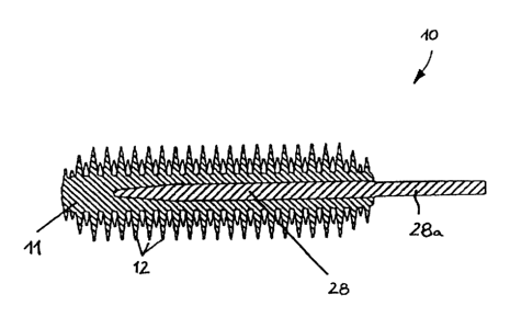
Fig. 24 shows an alternative embodiment of an applicator
brush 10 which has a rod-shaped reinforcing insert 28 made
from a fiber-reinforced plastic material. Part of the length
of the reinforcing insert 28 and the fingers 12 formed in one
piece thereon are injected with the elastomeric plastic
material of the support 11, wherein one end of the
reinforcing insert 28 is disposed in the support 11 and the
opposing end projects therefrom such that the projecting part
forms a holding or mounting section 28a where the applicator
brush can be directly grasped by the user or be mounted to a
further gripping or holding part. The figure shows that the
reinforcing insert 28 extends centrally in the support 11
through approximately 80% of its length, wherein the outer
diameter of the support is 3.0 to 3.5 times the diameter of
the reinforcing insert 28 such that the reinforcing insert is
CA 02367346 2001-09-14
22
covered by the elastic plastic material of the support 11
with a thickness which corresponds to approximately 1 to 1.2
times the diameter of the reinforcing insert 28. The front
end of the reinforcing insert 28 disposed in the support 11
has a separation from the front end of the support 11 which
is sufficient to provide same with the required flexibility.