Note: Descriptions are shown in the official language in which they were submitted.
' 20341-69729
CA 02367545 2002-O1-14
_1-
THERMALLY INSULATED CONTAINER FOR
JUVENILE STROLLER PUSH HANDLE
BACKGROUND AND SUMMARY
The present disclosure relates to juvenile strollers, and particularly to
stroller accessories. More particularly, the present disclosure relates to
storage units
adapted to be carried onboard a juvenile stroller.
Juvenile strollers are being adapted to carry various child-care items in
handy onboard locations in addition to carrying infants or other young
children.
Caregivers appreciate the convenience of being able to store child-care items
onboard
the stroller so that those items will be available to the caregiver when the
stroller is
being used to transport a child away from home or vehicle.
According to the present disclosure, a juvenile stroller includes a
stroller frame and a thermally insulated container configured to stare items
in a
temperature-controlled environment. The container is coupled to a console tray
mounted on a push handle included in the stroller frame to move therewith.
In some embodiments, the thermally insulated container is suspend
from the console tray and configured to include an interior storage region
accessible
through an access opening formed in a rear wall facing toward a person pushing
the
stroller. In another embodiment, the thermally insulated container is formed
to
include an interior storage region having a top opening and is coupled to a
lid frame
mounted on the push handle so that a lid mounted on the lid frame can be
opened and
closed to control access to the interior storage region through the top
opening. The
interior storage region of such container can also be accessed through an
access
opening formed in a rear wall facing toward a person pushing the stroller.
Additional features of the disclosure will become apparent to those
skilled in the art upon consideration of the following detailed description of
prefen:ed
embodiments exemplifying the best mode of carrying out the disclosure as
presently
perceived.
20341-69729
CA 02367545 2002-O1-14
-2-
BRIEF DESCRIPTION OF THE DRAWINGS
The detailed description particularly refers to the accompanying
figures in which:
Fig. 1 is a perspective view of a portable thermally insulated push
handle container in accordance with a first embodiment of this disclosure
adapted to
be mounted in a container receiver formed in a console tray mounted on the
push
handle of a juvenile stroller;
Fig. 2 is a perspective view of a portable thermally insulated container
adapted to be placed in a basket coupled to a stroller frame and arranged to
lie under a
seat coupled to the stroller frame as shown in Fig. 1;
Fig. 3 is a perspective view similar to Fig. 2 showing the container of
Fig. 2 after it has been opened;
Fig. 4 is a perspective view of ~ portable thermally insulated push
handle container in accordance with a second embodiment of this disclosure
adapted
to be mounted in a container receiver formed in a console tray mounted on the
push
handle of a juvenile stroller;
Fig. 5 is a perspective view of a portable thermally insulated container
adapted to be coupled to a rear portion of a thermally insulated container
arranged to
lie under a seat coupled to the stroller frame as shown in Fig. 4;
Fig. 6 is a rear perspective view of the thermallly insulated push handle
container of Fig. 4 showing a rear-access cover in an opened position;
Fig. 7 is a perspective view of a portable thermally insulated push
handle container in accordance with a third embodiment of this disclosure
adapted to
be mounted on handle arms included in a push handle of a juvenile stroller,
the
juvenile stroller further including a thermally insulated container mounted
under a
seat included in the juvenile stroller and formed to include a front-access
cover in an
opened position; and
Fig. 8 is a rear perspective view of the push handle container of Fig. 7
showing a rear-access cover in an opened position.
DETAILED DESCRIPTION OF THE DRAWINGS
20341-69729
CA 02367545 2002-O1-14
-3-
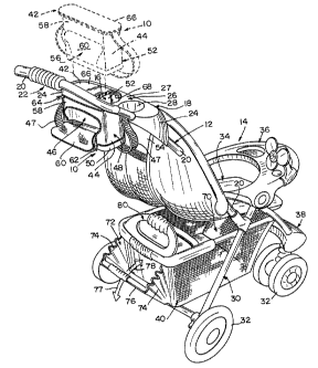
A thermally insulated container 10 is configured to store items in a
temperature-controlled environment from a perch on the push handle 12 of a
juvenile
stroller 14 as shown, for example, in Fig. 1. A second thermally insulated
push
handle container 110 is illustrated in Figs. 4 and 6, while a third thermally
insulated
push handle container 210 is shown in Figs. 7 and 8.
Each container 10, 110, 210 is configured to provide a thermally
insulated case in which caregivers can store child-care or other items to be
maintained
in a cooled environment. Such a thermally insulated case is adapted to r~eive
an ice
pack or any other suitable low-temperature source to lower the temperature in
an
interior storage region to a selected temperature target or range. Such a
thermally
insulated case is also adapted to receive a heat pack or any other suitable
high-
temperature source. Such containers fimction as a thermally insulated storage
region
to maintain products stored therein at a desired temperature relative to an
ambient
temperature outside the storage region for a desired period of time so that
cold
products stored in the thermally insulated storage region will be maintained
at their
cold temperature and warm products stored in the thermally insulated storage
region
will be maintained at their warm temperature.
Container 10 is configured to be located in a container receiver 16
included in a console tray 18 that is mounted on push handle 12 of stroller 14
as
shown, for example, in Fig. 1. Push handle 12 includes a pair of spaced-apart
handle
arms 20 and a grip handle 22 coupled to handle arms 20. Console tray 18
includes a
pair of spaced-apart side walls 24 and a top plate 26 formed to include an
aperhare-
defining container receiver 16. Each side wall 24 is configured to mount on
one of
handle arms 20 to support console tray 18 on push handle 12 in a location near
grip
handle 22. Top plate 26 is also formed to include a cup holder 28 configured
to hold
a cup, bottle, juice box, or other item. It is within the scope of this
disclosure to
provide other storage receptacles on console tray 18 (and the other console
trays
disclosed herein) to provide a convenient storage platform on push handle 12
within
easy reach of a caregiver pushing the stroller 14.
Juvenile stroller 14 includes a frame 30 and wheels 32, a seat 34, a tray
36, a footrest 38, and a basket 40 of any suitable shape and coupled to frame
30 in any
suitable manner. The push handle 12 is a part of frame 30 and may have any
suitable
20341-69729
CA 02367545 2002-O1-14
-4-
shape and size. Basket 40 is arranged to lie under seat 34 to provide
additional
storage capacity onboard stroller 14.
As shown in Fig. 1, thermally insulated container 10 includes a basket
support frame 42 and a basket 44 formed to include an interior storage region
46 and
suspended from basket 44. Console tray 18 includes a top surface 27 on top
plate 26
that is formed to include an opening into the container receiver 16 formed in
top plate
26 as shown, for example, in Fig. 1. Basket 44 is sized to pass thmugh the
opening in
top surface 27 of top plate 26 during movement of basket support frame 42 into
container receiver 16 formed in the top plate 26 of tray console 18. A
carrying strap
47 is coupled to either basket support frame 42 or basket 44 to facilitate
handling of
container 10 when container 10 is separated from console tray 18.
In the illustrated embodiment, basket support frame 42 is made of a
plastics material and basket 44 includes walls 48 coupled to basket support
frame 42
and made of a pliable material and a floor 50 coupled to walls 48 and made of
a
plastics material. It is within the scope of this disclosure to provide walls
48 and floor
50 with a wide variety of suitable shapes using any suitable materials. Walls
48
include a front wall 52 arranged to face toward a seat back 54 included in
seat 34 and
a rear wall 56 arranged to face away from seat back 54 as shown, for example,
in
Fig. 1.
Rear wall 56 of basket 44 includes a fixes portion 58 formed to include
an access opening into interior storage region 46, a cover portion or door 60,
and
means for fastening cover portion 60 to fixed portion 58 to permit movement of
cover
portion 60 relative to fixed portion 58 to open and close the access opening
into
interior storage region 46. Although the fastening means is a zipper 62 in the
illustrated embodiment, it is within the scope of this disclosure to use any
suitable
fastener such as snaps, buttons, ties, and hook-and-loop fasteners. It is
within the
scope of this disclosure to provide another fastener such as zipper 64 along
an
interface between basket walls 48 and basket support frame 42 to provide a
closable
top opening into interior storage region 46 that is usable, for example, when
the
thermally insulated container 10 is separated from console tray 18.
In the illustrated embodiment shown in Fig. l, a perimeter edge 66 of
basket support frame 42 sets on an interior ledge 68 formed in top plate 26 of
console
20341-69729
CA 02367545 2002-O1-14
-5-
tray 18 and associated with container receiver 16 to suspend thermally
insulated
container 10 in container receiver 16. In such a suspended position, basket
walls 48
extend downwardly from top plate 26 to lie under console tray 18 and basket 44
lies
in spaced-apart relation to cup holder 28. It is within the scope of this
disclosure to
S use other connectors to establish a fixed position of basket support frame
42 in
container receiver 16. It is also within the scope of this disclosure to mount
perimeter
edge 66 of basket support frame 42 on top surface 27 or another part of top
plate 26 of
console tray 18. When container 10 is located in container receiver 16,
carrying strap
47 is arranged to hang or otherwise lie below console tray 18 in an out-of the-
way
location.
As shown, for example, in Fig. 1, the basket 40 arranged to lie under
seat 34 is formed to include a large storage cavity 70 of fixed volume and a
smaller
expandable cavity 72 of variable volume located to the rear of large storage
cavity 70.
Corrugated foldable side walls 74 and a grippable rear wall 76 cooperate to
form
expandable cavity 72 and can be moved in directions 77 or 78 to change the
volume
of expandable cavity 72.
A thermally insulated container 80, configured to be stored in
underseat basket 40 of stroller 14, as shown in Fig. 1, is shown in Figs. 2
and 3.
Container 80 includes side walls 81, floor 82 coupled to side walls 81, end
wall 83
coupled to side walls 81 and floor 82, and a handle portion 84 coupled to each
of side
walls 81. Container 80 is formed to include an interior storage region 85 that
is
accessible by opening closure 86 using fastener 87 or by opening closure 88
using
fastener 89. Closure 86 is located in one of side walls 81 while closure 88 is
located
in a top portion 90 and an end wall 91. Closure 88 includes side portion 88a
and top
portion 88b. When closed as shown, for example, in Fig. 2, handle portions 84
mate
to form handle 92 and hook-and-loop fasteners 93 or other fasteners can be
used to
couple one handle portion 84 to the other handle portion 84.
A thermally insulated container 110 associated with a console tray 118
mounted on a push handle 112 included in a stroller 114 is illustrated in
Figs. 4 and 6.
Stroller 114 includes frame 130, wheels 132, seat 134, tray 136, footrest 138,
basket
140, and canopy 141. Push handle 112 includes two spaced-apart handle arms 120
and a grip handle 122 coupled to handle arms 120.
' 20341-69729
CA 02367545 2002-O1-14
-6-
Console tray 118 includes a pair of spaced-apart side walls 124, a front
wall 125, and a top plate 126 formed to include two cup holders 228. Top plate
126 is
coupled to each of side walls 124 and arranged to span a space therebetween as
suggested in Fig. 6. Front wall 125 is also coupled to each of side walls 124
and is
coupled to a front edge of top plate 126 as shown best in Fig. 4. Top plate
126, front
wall 125, and side walls 124 cooperate to define a container receiver 116
therebetween as shown best in Fig. 6. Container 110 is mounted in container
receiver
116 to extend downwardly from top plate 126 and lie in a space between handle
arms 120.
Container 110 includes walls 148 coupled to top plate 116 and/or other
portions of console tray 118 and a floor 150 coupled to walls 148. In the
illustrated
embodiment, walls 148 and floor 150 are made of a pliable material. Walls 148
include a front wall 152 arranged to face toward front wall 125 of console
tray 118
and a rear wall 156 arrang~l to face away from console tray wall 125 as in
Figs. 4
and 6.
Rear wall 156 of container 110 includes a fixed portion 158 formed to
include an access opening into an interior storage region 146 formed in
container 110,
a cover portion or door 160, and means for fastening cover portion 160 to
fixed
portion 158 to permit movement of cover portion 160 relative to fixed potion
158 to
open and close the access opening into interior storage region 146. Although
the
fastening means is a zipper 162 in the embodiment illustrated in Figs. 4 and
6, it is
within the scope of this disclosure to use any suitable fasteners such as
snaps, buttons,
ties, and hook-and-Ioop fasteners. It is also within the scope of this
disclosure to
provide means 161 for holding ice packs 163 or heat packs (not shown) in
predetermined locations inside interior storage region 146 as suggested in
Fig. 6. In
the illustrated embodiment, such pack holder means 161 includes interior walls
coupled to walls 148 and floor 150 to form a pack receiver chamber therein. It
is also
within the scope of this disclosure to mount a pack holder 161 on or in close
proximity to seat 134 as shown, for example, in Fig. 4 to provide means for
cooling or
warming a juvenile at rest on the seat 134.
As shown, for example, in Fig. 4, the basket 140 arranged to lie under
seat 134 is formed to include a thermally insulated interior storage region
141 that is
20341-69729
CA 02367545 2002-O1-14
_7_
accessible through a side wall by opening closure 186 using fastener 187.
Further, a
thermally insulated container 180, configured to be coupled to a rear portion
of
underseat basket 14 as shown in Fig. 4, is shown in Fig. 5. Container 180
includes
side walls 181, floor 182 coupled to side walls 181, end walls 183 coupled to
side
walls 181 and floor 182, and a handle 192 coupled to a lid 193. Lid 193 is
fastened to
walls 181, 183 by zipper 194. Hooks 195 are coupled to lid 193 and arranged to
provide means for mating with underseat basket 140 to support container 180 on
basket 140 a shown, for example, in Fig. 4.
A thermally insulated container 210 associated with a console tray 218
configured to mount on a push handle 212 included in a stroller 214 is
illustrated in
Figs. 7 and 8. Stroller 214 includes frame 230, wheels 232, seat 234, tray
236,
footrest 238, basket 240, and canopy 241. Push handle 212 includes two spaced-
apart
handle arms 220 and a grip handle 222 coupled to handle arms 220.
Console tray 218 includes a lid frame 201 configured to mount on
handle arms 220 of push handle 212 and a lid or top plate 202 mounted on lid
frame
201 for movement relative to lid frame 201 to open and close a top opening
formed in
thermally insulated container 210 and located under lid 202. In the
illustrated
embodiment, lid 202 is mounted on a hinge 203 to pivot about a hinge axis 204
relative to lid frame 201. A carrying strap 247 is coupled to lid frame 201 to
facilitate
handling of container 210 when it is separated from stroller 214.
Container 210 includes walls 248 coupled to lid frame 201 and a floor
250 coupled to walls 248. Walls 248 and floor 250 cooperate to form an
interior
storage region 246 in container 210. In the illustrated embodiment, wall 248
and floor
250 are made of a pliable material. Walls 148 include a front wall 252
arranged to
face toward canopy 241 and a rear wall 256 arranged to face away from canopy
241
as suggested in Figs. 7 and 8.
Rear wall 256 of container 210 includes a fixed portion 258 formed to
include an access opening into an interior storage region 246 formed in
container 210,
a cover portion or door 260, and means for fastening cover portion 260 to
fixed
portion 258 to permit movement of cover portion 260 relative to fixed portion
258 to
open and close the access opening into interior storage region 246. Although
the
fastening means is a zipper 262 in the embodiment illustrated in Figs. 7 and
8, it is
20341-69729
CA 02367545 2002-O1-14
_g_
within the scope of this disclosure to use any suitable fastener such as
snaps, buttons,
ties, and hook-and-loop fasteners.
Lid frame 201 of console tray 218 includes a pair of side walls 205
arranged to lie in spaced-apart relation to one another to define a container
receiver
216 therebetween as suggested in Figs. 7 and 8. Each side wall 205 is formed
to
include an inclined channel 206 defined by a curved concave wall 207 shaped
and
sized to receive a tubular section of one of the handle arms 220 therein. Lid
frame
201 further includes a rear wall 208 coupled to each of the side walls 205.
Rear wall
208 is "cut away" as shown, for example, in Fig. 7 to provide lowermost
openings
into each of the inclined channels 206 formed in the side walls 205. Rear wall
208
includes a lowermost edge 209 and floor 250 is arranged to lie below and in
spaced-
apart relation to lowermost edge 209 of rear wall 208.
As shown, for example, in Fig. 7, the basket 240 arranged to lie under
seat 234 is formed to include a thermally insulated interior storage region
241.
Interior storage region 241 is accessible through a front wall located between
a front
edge of seat 234 and footrest 238 by opening a closure 286 using fastener 287.