Note: Descriptions are shown in the official language in which they were submitted.
CA 02367733 2002-01-11
SNAP LOCK BALANCE SHOE AND SYSTEM FOR A PIVOTABLE WINDOW
Related Application
This application incorporates by reference in its entirety and claims priority
to U.S.
Provisional Patent Application Serial No. 60/261,501 entitled Snap Lock
Balance Shoe
and System for a Pivotable Window filed on January 12, 2001.
Field of the Invention
This invention relates to a window balance system for use in a pivotable
window
assembly.
Background of the Invention
This invention relates to the field of tilt-in windows. More particularly this
invention relates to a balance shoe of a window balance system used in
conjunction with a
pivot bar mounted on a window sash for rotating the window sash relative to a
window
frame.
Typical pivotable double hung windows include two window sashes disposed in
tracks located in a window frame to allow vertical sliding movement of the
sashes. Pivot
bars are provided to allow rotational movement of a pivotable window sash
about the
pivot bars to facilitate cleaning of glazing. To control vertical movement,
window
balances are used so that the window sashes remain in a position in which they
are placed.
Balance shoes are used to guide the rotational movement of the window sashes
with
respect to the window frame. Typically, the balance shoes are coupled to
window
balances with a connecting member. See, for example, U.S. Pat. No. 6,119,398,
entitled
"Tilt Window Balance Shoe Assembly with Three Directional Locking" issued to
H. Dale
Yates, Jr., the disclosure of which is herein incorporated by reference in its
entirety.
One of the problems with balance shoes and window balances for pivotable
double
hung windows is that they are difficult to install. In order to install a
pivotable double
hung window with balance shoes and window balances, the following installation
steps
typically must be followed. First, before the window frame is assembled, the
balance
shoes are inserted into jamb tracks. Next, connecting members are used to
attach the
balance shoes to the window balances. The balance shoes generally have an
opening to
accept the pivot bars that are mounted on window sashes. Finally, the sashes
are made
operable by inserting the pivot bars into the balance shoes and rotating the
window sash up
CA 02367733 2002-01-11
to a vertical position in the jamb tracks. The installation process is rather
complex and
difficult. Repair costs for replacing balance shoes are also significant. In
order to change
a malfunctioning or failed balance shoe, the jamb tracks either need to be
deformed or
replaced to gain access to the problematic balance shoe for removal and
replacement.
Summary of the Invention
In general, in one aspect, the invention relates to a balance shoe. The
balance shoe
includes a frame, a locking member at least partially disposed within the
frame, a cam in
communication with the locking member, and a connecting device for attaching
the
balance shoe within a window balance. Embodiments of the invention can include
the
following features. The connecting device can include one or more retractable
tabs that
engage the window balance directly. The frame can further include a frame
pocket sized
to receive a fastener. The cam can include at least one camming surface and a
keyhole
opening for receiving a pivot bar attached to a window sash. The cam is at
least partially
housed within the frame and is disposed within a space enclosed by the locking
member.
Upon rotating the cam with the pivot bar, the locking member engages the
window jamb.
In one embodiment, the locking member includes two opposing ends integrally
connected
by a spring member. The cam is located within a space between the opposing
ends of the
locking member, and upon rotating the cam with the pivot bar, the opposing
ends engage
the window jamb. In another embodiment, the locking member includes a plate,
which is
parallel to a back surface of the frame. The cam is located within a space
between the
plate and the frame such that rotating the cam with the pivot bar forces the
plate to engage
the window jamb.
In another aspect, the invention relates to an inverted window balance system
for
use within a pivotable double hung window assembly. The inverted window
balance
system includes a rigid U-shaped channel with a plurality of openings in the
channel walls
for securing the contents in the channel, which include an extension spring, a
system of
pulleys, a cord to connect the extension spring via the system of pulleys with
the window
sash, and a balance shoe. The balance shoe includes a frame, a locking member
at least
partially disposed within the frame, a cam in communication with the locking
member,
and a connecting device for attaching the balance shoe within the rigid U-
shaped channel.
Embodiments of this aspect of the invention can include the following
features. At least a
portion of the balance shoe is disposed within the rigid U-shaped channel. The
connecting
device can include one or more retractable tabs for engaging the rigid U-
shaped channel.
-2-
CA 02367733 2007-12-06
The retractable tabs can partially extend through at least one of the
plurality of openings in
the rigid U-shaped channel. The balance shoe can be further secured to the
rigid U-shaped
channel with a fastener that interfaces with a frame pocket in the balance
shoe. The cam can
include at least one camming surface and a keyhole opening for receiving a
pivot bar attached
to a window sash. The cam is at least partially housed within the frame and is
disposed
within a space enclosed by the locking member. Upon rotating the cam with the
pivot bar,
the locking member engages the window jamb. In one embodiment, the locking
member
includes two opposing ends integrally connected by a spring member. The cam is
located
within a space between the opposing ends of the locking member, and upon
rotating the cam
with the pivot bar, the opposing ends engage the window jamb. In another
embodiment, the
locking member includes a plate, which is parallel to a back surface of the
frame. The cam is
located within a space between the plate and the frame such that rotating the
cam with the
pivot bar forces the plate to engage the window jamb.
In still another aspect, the invention relates to a method for installing an
inverted
window balance system within a window jamb in a window frame comprising the
steps of:
providing an inverted window balance system comprising: a U-shaped channel
with a
plurality of openings, a spring connected to a system of pulleys located
within the U-shaped
channel; a cord with a first cord end and a second cord end, the first cord
end connected and
threaded through the system of pulleys, the second cord end connected to a
jamb mounting
attachment; and a balance shoe comprising: a frame comprising a frame bottom
surface, a
frame front surface and two frame edge surfaces; a locking member at least
partially disposed
within the frame; a cam in communication with the locking member; and a
connecting device
for attaching the balance shoe within the U-shaped channel; inserting the
inverted window
balance system within a jamb track of the window jamb such that an axis
extending along a
longitudinal direction of the U-shaped channel is perpendicular to a back wall
of the jamb
track and an axis that is perpendicular to the two frame edge surfaces is
parallel to the back
wall while the frame front surface faces a side wall of the jamb track;
rotating the inverted
window balance system within the jamb track 90 degrees about the axis
extending along the
longitudinal direction of the U-shaped channel such that the frame front
surface faces down;
and rotating the inverted window balance system 90 degrees about the axis that
is
perpendicular to the two frame edge surfaces such that the frame bottom
surface faces in a
downward direction.
-3-
CA 02367733 2004-01-20
In accordance with another aspect of the present invention there is provided a
balance shoe for a window balance system, the balance shoe comprising a frame
comprising
an enlarged first end and a second end, wherein the second end is adapted to
be received by
a U-shaped channel of a window balance; a locking member proximal to the
enlarged first
end; a cam in communication with the locking member; and a connecting device
for
attaching the balance shoe within the U-shaped channel of the window balance.
In accordance with another aspect of the present invention there is provided
a method for installing a window balance system within a window jamb in a
window frame
comprising the steps of providing a window balance system comprising a U-
shaped
channel; a spring connected to a system of pulleys located within the U-shaped
channel; a
cord with a first cord end and a second cord end, the first cord end connected
and threaded
through the system of pulleys, the second cord end connected to a jamb
mounting
attachment; and a balance shoe comprising a frame comprising an enlarged first
end
comprising a frame bottom surface; and a second end comprising a frame front
surface and
two frame edge surfaces; a locking member proximal to the enlarged first end
of the frame;
a cam in communication with the locking member, and a connecting device for
attaching
the balance shoe to the U-shaped channel; inserting the enlarged first end of
the frame of the
window balance system within a jamb track of the window jamb such that an axis
extending
along a longitudinal direction of the U-shaped channel is perpendicular to a
back wall of the
jamb track and an axis that is perpendicular to the two frame edge surfaces is
parallel to the
back wall while the frame front surface faces a side wall of the jamb track;
rotating the
window balance system within the jamb track 90 degrees about the axis
extending along the
longitudinal direction of the U-shaped channel such that the frame front
surface faces down;
and rotating the window balance system 90 degrees about the axis that is
perpendicular to
the two frame edge surfaces such that the frame bottom surface faces in a
downward
direction.
In accordance with another aspect of the present invention there is provided a
window balance system comprising a U-shaped channel comprising a plurality of
openings;
a spring connected to a system of pulleys located within the U-shaped channel;
a cord with
a first cord end and a second cord end, the first cord end connected and
threaded through the
system of pulleys, the second cord end connected to a jamb mounting
attachment; and a
3a
CA 02367733 2004-01-20
balance shoe, wherein the balance shoe comprises a frame comprising an
enlarged first end
and a second end, wherein the second end is adapted to be received by a U-
shaped channel
of an inverted window balance; a locking member proximal to the enlarged first
end; a cam
in communication with the locking member; and a connecting device for
attaching the
balance shoe within the U-shaped channel of the window balance.
In accordance with another aspect of the present invention there is provided
a method for installing a window balance system within a window jamb in a
window frame
comprising the steps of providing a window balance system comprising a U-
shaped
channel; and a balance shoe comprising a frame including a frame bottom
surface, a frame
front surface and two frame edge surfaces; inserting the window balance system
within a
jamb track of the window jamb such that an axis extending along a longitudinal
direction of
the U-shaped channel is perpendicular to a back wall of the jamb track and an
axis that is
perpendicular to the two frame edge surfaces is parallel to the back wall
while the frame
front surface faces a side wall of the jamb track; rotating the window balance
system within
the jamb track 90 degrees about the axis extending along the longitudinal
direction of the U-
shaped channel such that the frame front surface faces down; and rotating the
window
balance system 90 degrees about the axis that is perpendicular to the two
frame edge
surfaces such that the frame bottom surface faces in a downward direction.
In accordance with another aspect of the present invention there is provided
a window balance system comprising a U-shaped channel comprising a plurality
of
openings; a spring connected to a system of pulleys located within the U-
shaped channel;
a cord with a first cord end and a second cord end, the first cord end
connected and threaded
through the system of pulleys, the second cord end connected to ajamb mounting
attachment; and a balance shoe, wherein the balance shoe comprises a frame
comprising an
enlarged first end and a second end, wherein at least a portion of the second
end of the
frame is disposed within the U-shaped channel; a locking member proximal to
the enlarged
first end; a cam in communication with the locking member; and a connecting
device
comprising one or more resilient tabs for attaching the balance shoe within
the U-shaped
channel of the window balance, wherein the one or more resilient tabs extend
at least
partially through a corresponding number of the plurality of openings in the U-
shaped
channel.
3b
CA 02367733 2006-11-20
In accordance with another aspect of the present invention there is provided a
window balance system comprising a U-shaped channel comprising a plurality of
openings;
a spring connected to a system of pulleys located within the U-shaped channel;
a cord with
a first cord end and a second cord end, the first cord end connected and
threaded through the
system of pulleys, the second cord end connected to a jamb mounting
attachment; and a
balance shoe, wherein the balance shoe comprises a frame comprising an
enlarged first end
and a second end, wherein the second end is adapted to be received by the U-
shaped
channel, and wherein the second end of the frame of the balance shoe further
forms a pocket
positioned in the second end of the frame adapted to mate with a rivet; a
locking member
proximal to the enlarged first end; a cam in communication with the locking
member; and
a connecting device for attaching the balance shoe within the U-shaped channel
of the
window balance.
In accordance with another aspect of the present invention there is provided
an
inverted window balance system comprising: a U-shaped channel comprising a
plurality of
openings; a spring connected to a system of pulleys located within the U-
shaped channel; a
cord with a first cord end and a second cord end, the first cord end connected
and threaded
through the system of pulleys, the second cord end connected to a jamb
mounting
attachment; and a balance shoe, wherein the balance shoe comprises: a frame; a
locking
member at least partially disposed within the frame; a cam in communication
with the
locking member; and a connecting device for attaching the balance shoe within
the U-
shaped channel.
In accordance with another aspect of the present invention there is provided a
balance shoe for a window balance system adapted to be received in a window
jamb track,
the balance shoe comprising: a frame comprising an enlarged first end and a
second end,
wherein at least a portion of the second end is adapted to be directly
attached to a U-shaped
channel of the window balance system; a locking member proximal to the
enlarged first
end, the locking member adapted to engage the jamb track; and a cam in
communication
with the locking member.
In accordance with another aspect of the present invention there is provided a
balance shoe for a window balance system having a U-shaped channel, the system
adapted
to be received within a window jamb track of a window jamb, the balance shoe
comprising:
a frame comprising a first end and a second end, at least a portion of the
second end adapted
3c
CA 02367733 2007-12-06
to be received in at least a portion of the U-shaped channel of the window
balance system; a
locking member proximal to the first end; and a cam in communication with the
locking
member, wherein rotation of the cam causes the locking member to engage the
jamb track
when installed.
In accordance with another aspect of the present invention there is provided a
window
balance system adapted to be received in a window jamb track, the balance
system
comprising: a U-shaped channel; a spring connected to a system of pulleys
located within the
U-shaped channel; a cord with a first cord end and a second cord end, the
first cord end
connected and threaded through the system of pulleys, the second cord end
connected to a
jamb mounting attachment; and a balance shoe in accordance with the above
balance shoe.
In accordance with another aspect of the present invention there is provided a
balance
shoe for a window balance system adapted to be received in a window jamb
track, the
balance shoe comprising: an elongate portion adapted to be received at least
partially within a
channel of a window balance system, the channel adapted to be removeably
installed in the
window jamb track; a cam at least partially housed within the elongate
portion, the cam
defining a recess adapted to accept a pivot bar, wherein the cam rotates in
response to a
rotation of a pivot bar; and a locking member in communication with the cam,
wherein when
installed in a window balance system in a window jamb track, the rotation of
the cam forces
the locking member toward a window jamb track.
In accordance with another aspect of the present invention there is provided a
window
balance system adapted to be received in a window jamb track, the window
balance system
comprising: a channel adapted to be removeably installed within the window
jamb track; and
a balance shoe comprising: a first end; a second end, at least a portion of
the second end
adapted to be received in the channel; a locking member; and a cam in
communication with
locking member, wherein the cam is positionable in at least a first position
that applies a
force to the locking member, thereby forcing the locking member toward a
window jamb
track when the window balance system is installed in a window jamb track.
In accordance with another aspect of the present invention there is provided a
window
balance system adapted to be received in a window jamb track, the system
comprising: a
channel defining at least one opening and comprising a longitudinal axis, the
channel adapted
3d
CA 02367733 2007-12-06
to be removeably installed in the window jamb track; a frame having an
enlarged end, the
enlarged end having a width greater than a width of the channel and mounted to
the channel,
the enlarged end adapted to at least partially guide a window sash in response
to a movement
thereof; a connecting device adapted to directly attach the frame within the
channel; a cam
rotatably mounted relative to the channel, wherein the cam is substantially
aligned with the
longitudinal axis of the channel; and a locking member in communication with
the cam,
wherein a rotation of the cam forces the locking member toward the jamb track
when the
window balance system is installed in the window jamb.
3e
CA 02367733 2002-01-11
These and other features of the invention will be made apparent from the
following
description taken in conjunction with the accompanying drawings.
Brief Description of the Drawings
In the drawings, like reference characters generally refer to the same parts
throughout the different views. Also, the drawings are not necessarily to
scale, emphasis
instead generally being placed upon illustrating the principles of the
invention.
FIG. 1 is a perspective view of a pivotable double hung window assembly;
FIG. 2A is a rear view of inverted window balance system for use with a prior
art
balance shoe;
FIG. 2B is a rear view of a window balance;
FIG. 3A is one perspective view of an embodiment of a snap lock balance shoe
of
the present invention;
FIG. 3B is another perspective view of the embodiment of the snap lock balance
shoe of FIG. 3A;
FIG. 3C is a rear view of one embodiment of a snap lock inverted balance
system;
FIG. 3D is a bottom view of one embodiment of a snap lock balance shoe;
FIG. 3E is a front view of one embodiment of a snap lock balance shoe;
FIG. 3F is a side view of one embodiment of a snap lock balance shoe;
FIG. 4 is a perspective view of an embodiment of a snap lock balance shoe of
the
present invention;
FIG. 5A is one perspective view of another embodiment of a snap lock balance
shoe of the present invention;
FIG. 5B is another perspective view of the embodiment of the snap lock balance
shoe of FIG. 5A;
FIG. 6A is a perspective view of one embodiment of a balance shoe of the
invention and a rigid U-shaped channel;
FIG. 6B is a perspective view showing the first step of connecting one
embodiment
of the balance shoe of the invention to the rigid U-shaped channel;
FIG. 6C is a perspective view showing the second step of connecting one
embodiment of the balance shoe of the invention to the rigid U-shaped channel;
FIG. 6D is a perspective view showing one embodiment of the balance shoe of
the
invention connected to the rigid U-shaped channel;
-4-
CA 02367733 2002-01-11
FIG. 7A is a front view of a prior art balance shoe attached to a rigid U-
shaped
channel;
FIG. 7B is a side view of the prior art balance shoe attached to the rigid U-
shaped
channel;
FIG. 8A is a front view of one embodiment of a snap lock balance shoe of the
present invention attached to a rigid U-shaped channel;
FIG. 8B is a side view of one embodiment of the snap lock balance shoe of the
present invention attached to the rigid U-shaped channel;
FIG. 9 is a front view of a window assembly including one snap lock inverted
window balance system of the present invention and one prior art inverted
window
balance system installed in a window frame;
FIG. l0A is a side view illustrating the first step of installing the snap
lock inverted
window balance system of the invention into the jamb track;
FIG. l OB is a front view illustrating the first step of installing the snap
lock
inverted window balance system of the invention into the jamb track;
FIG. 11A is a side view illustrating the second step of installing the snap
lock
inverted window balance system of the invention into the jamb track;
FIG. 11B is a front view illustrating the second step of installing the snap
lock
inverted window balance system of the invention into the jamb track;
FIG. 12A is a side view illustrating the third step of installing the snap
lock
inverted window balance system of the invention into the jamb track;
FIG. 12B is a front view illustrating the third step of installing the snap
lock
inverted window balance system of the invention into the j amb track;
FIG. 13A is a side view illustrating the last step of installing the snap lock
inverted
window balance system of the invention into the jamb track; and
FIG. 13B is a front view illustrating the last step of installing the snap
lock
inverted window balance system of the invention into the jamb track.
Detailed Description of the Invention
Referring to FIG. 1, shown is a pivotable double hung window assembly 100 in
which a snap lock balance shoe constructed in accordance with the teachings of
the
present invention can be used. The pivotable double hung window assembly 100
includes
of a window frame 102, a pivotable lower window sash 104, a pivotable upper
window
sash 106, and a window jamb 107. The pivotable lower window sash 104 and the
-5-
CA 02367733 2002-01-11
pivotable upper window sash 106 slide vertically in jamb track 108 within the
window
jamb 107, while also being able to pivot about a pivot bar 114, as shown in
FIG. 9.
FIG. 2A shows a rear view of an inverted window balance system 120 for use in
the pivotable double hung window assembly 100. The inverted window balance
system
120 includes an inverted window balance 122 used for balancing the weight of
either the
pivotable lower window sash 104 or the pivotable upper window sash 106 at any
vertical
position within the window frame 102, and a prior art balance shoe 110 for
guiding the
rotation of the pivotable lower window sash 104 about the pivot bar 114. A
hanging
connector 112 connects the prior art balance shoe 110 to the inverted window
balance 122.
The inverted window balance 122 includes an extension spring 126 connected to
a system
of pulleys 128 housed within a rigid U-shaped channel 130, and a cord 132 for
connecting
the system of pulleys 128 to a jamb mounting attachment 134. The jamb mounting
attachment 134 is used for connecting the inverted window balance system 120
to the
window jamb 107. One difference between the inverted window balance 122 and a
window balance 140, shown in FIG. 2B, includes the placement of the extension
spring
146 above a system of pulleys 148 within the rigid U-shaped channel 150. A
cord 152
connects the system of pulleys 148 to a jamb mounting attachment 154. Another
difference is that while inverted window balances 122 travel with either the
pivotable
lower window sash 104 or pivotable upper window sash 106, the window balance
140
remains in a fixed position in the window jamb 107 due to an attachment to the
window
jamb 107 through an attachment opening 155.
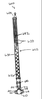
FIGS. 3A and 3B are perspective views of a snap lock balance shoe 210 of one
embodiment of the present invention. The snap lock balance shoe 210 has a
frame 211 in
which is housed a connecting device 212, a locking device 214, and a cam 218.
The
connecting device 212 can be integral with the frame 211 and attaches the snap
lock
balance shoe 210 directly within an inverted window balance 622, shown in FIG
3C. The
inverted window balance 622 in combination with the snap lock balance shoe 210
forms a
snap lock inverted window balance system 600. The inverted window balance 622
includes an extension spring 626 connected to a system of pulleys 628 housed
within a
rigid U-shaped channel 630, and a cord 632 for connecting the system of
pulleys 628 to a
jamb mounting attachment 634, such as a cord terminal or hook.
In the depicted embodiment, the connecting device 212 is a pair of retractable
tabs
that snap into the rigid U-shaped channel 630. In other embodiments, other
connecting
devices such as a screw, may be used to secure the frame 211 to the rigid U-
shaped
-6-
CA 02367733 2002-01-11
channel 630. A fastener 635 located in the inverted window balance 622 can be
used to
further secure the connection between the snap lock balance shoe 210 and the
inverted
window balance 622. To accommodate the fastener 635, the snap lock balance
shoe 210
can form a connection pocket 213 sized to receive or mate with the fastener
635.
Another element of the snap lock balance shoe 210 visible in FIG. 3A is a
keyhole
opening 219 located within the cam 218. The keyhole opening 219 is sized to
accept the
pivot bar 114 extending from either the pivotable lower window sash 104 or the
pivotable
upper window sash 106, and serves as a connection point between the pivotable
lower or
upper window sash 104, 106 and the snap lock balance shoe 210. FIG. 3B shows a
perspective view of the snap lock balance shoe 210 showing another face of the
cam 218.
In the embodiment shown in FIG. 3B, the locking device 214 surrounds the cam
218 and includes of a pair of opposing ends 215 connected by a spring member
216.
When the pivotable lower window sash 104 is tilted open, the pivot bar 114
rotates, which
in turn rotates the cam 218 forcing the opposing ends 215 outward to engage
the jamb
track 108 of the window frame 102, thereby locking the balance shoe 210 in
that location.
FIGS. 3D-3F show different views of one of the embodiments of the snap lock
balance shoe 210 of the invention. FIG. 3D is a bottom view of the snap lock
balance
shoe 210 that shows a frame bottom surface 230. FIG. 3E is a front view of the
same
embodiment of the snap lock balance shoe 210 that illustrates a frame front
surface 240,
and FIG. 3F is an side view that shows one of the two frame edge surfaces 250
of the snap
lock balance shoe 210.
FIG. 4 shows another embodiment of a snap lock balance shoe 310. The snap lock
balance shoe 310 has an elongated frame 311 in which is housed a connecting
device 312,
a locking device 314, and a cam 318. Within the cam is a keyhole opening 319
sized to
receive the pivot bar 114. The elongated frame 311 has a length L 325 that is
greater than
about 1.25 inches. When attached to the rigid U-shaped channel 630, the
balance shoe
310 extends further outward from the rigid U-shaped channel 630 than the
balance shoe
210 attached to a similar sized rigid U-shaped channel 630. The balance shoe
310 allows
a fixed-sized rigid U-shaped channel 630 to be used in a larger window having
a greater
travel distance by extending the length of the entire window balance system by
having a
longer balance shoe 310. One of the advantages of the present invention is
that an installer
can create a custom window balance system for a particular window by fitting a
fixed-
length rigid U-shaped channel 630 with an appropriately sized snap lock
balance shoe.
7
CA 02367733 2002-01-11
Referring to FIGS. 5A-5B, shown is another embodiment of the present invention
of a snap lock balance shoe 410. The snap lock balance shoe 410 has a locking
member
422 which engages a back wall of the jamb track 108 locking the balance shoe
410 in that
location. The locking member 422 is partially disposed in the frame 411 and
includes a
plate 423 that engages the back wall of the jamb track 108. The balance shoe
410 also
includes a frame 411, a connecting device 412, and a cam 418. The cam 418 is
partially
disposed within the frame 411 in a space enclosed by the locking member 422.
The cam
418 includes a keyhole opening 419 sized to receive the pivot bar 114. Upon
rotation of
the cam 418 with the pivot bar 114, the locking member 422 is forced away from
the
frame 411 towards the back wall of the jamb track 108, thereby anchoring the
balance
shoe 410 in that location within the window frame 102.
FIGS. 6A - 6D show one embodiment of a method for securing the snap lock
balance shoe 210 within a rigid U-shaped channel 630 with multiple openings
638. It
should be noted that each opening 638 on one side of the rigid U-shaped
channel 630 has a
corresponding opening 638 on the other side of the rigid U-shaped channel 630
to form a
pair of openings. The first step, shown in FIG. 6A, is to place a fastener
635, such as a
rivet, in one of the pairs of openings 638 in the rigid U-shaped channel 630.
The next
step, as depicted in FIG. 6B, is to slide the snap lock balance shoe 210 into
the rigid U-
shaped channel 630 such that the fastener 635 is received in the connection
pocket 213 of
the snap lock balance shoe 210. As shown in FIG. 6C, the snap lock balance
shoe 210 is
then rotated down so that the front frame surface 240 is aligned with a bottom
wall 636 of
the rigid U-shaped channel 630. FIG. 6D shows the last step of attaching the
snap lock
balance shoe 210 within the rigid U-shaped channel 630. In this step, the
connecting
device 212 of the snap lock balance shoe 210 snaps into one of the pairs of
openings 638
located on the rigid U-shaped channel 630. In alternative embodiments the
connection
device 212 of the snap lock balance shoe 210 can extend through off-set
openings in the
rigid U-shaped channel 630. In some embodiments, the snap lock balance shoe
210 is
attached to the rigid U-shaped channel 630 with the fastener 635. In other
embodiments,
the snap lock balance shoe 210 is attached to the rigid U-shaped channel 630
without the
fastener 635. It should also be noted that in some embodiments, the snap lock
balance
shoe 210 can be aligned and secured to the rigid U-shaped channel 630 such
that the front
frame surface 240 faces upwards instead of downwards as depicted in FIG. 6D.
FIG. 7A is a front view of the prior art balance shoe 110 attached to the
rigid U-
shaped channel 130. The rigid U-shaped channel 130 is connected to the prior
art balance
-8-
CA 02367733 2002-01-11
shoe 110 by the hanging connector 112. No part of the prior art balance shoe
1101ies
within the rigid U-shaped channel 130. FIG. 7B is a side view of the prior art
balance
shoe 110 attached to the rigid U-shaped channel 130 illustrating channel
openings 137.
Fasteners (not shown) are installed through the channel openings 137 to secure
the
hanging connector 112 to the rigid U-shaped channel 130.
Referring to FIGS. 8A and 8B, shown is an embodiment of the snap lock balance
shoe 210 of the present invention attached to the rigid U-shaped channel 630.
The snap
lock balance shoe 210 is directly attached within the rigid U-shaped channel
630 by a
connecting device 212 located on the frame 211 of the snap lock balance shoe
210. The
connecting device 212 extends through a pair of openings 638 located on the
rigid U-
shaped channe1630.
FIG. 9 is a front view of a pivotable double hung window assembly 800 in which
an inverted window balance 122 is attached to a prior art balance shoe 110 by
using the
hanging connector 112, and the inverted window balance 622 is attached to the
snap lock
balance shoe 210 of an embodiment of the present invention. Pivot bars 114, as
shown in
FIG. 9, are secured to the pivotable lower window sash 104. The pivot bars 114
are
slidably receivable by both the prior art balance shoe 110 and the snap lock
balance shoe
210 and serve as connections between the pivotable lower window sash 104 and
respective
inverted window balances 122, 622.
An advantage of the type of balance shoe presently disclosed is that the snap
lock
balance shoe 210 is attached within the rigid U-shaped channel 630 resulting
in a longer
rigid U-shaped channel 630 than in the inverted balance systems 120 for a
given window
sash. The longer rigid U-shaped channel 630 of the inverted window balance 622
allows
for the use of longer extension springs that provide greater control of the
vertical
positioning of the window sash than a shorter rigid U-shaped channel 130 with
a shorter
extension spring. Another advantage of the present invention is that the snap
lock balance
shoe 210 contains a smaller number of parts than prior art balance shoes 110.
One installation method used to place a snap lock inverted window balance
system
600 within the jamb tracks 108 is schematically illustrated in the remaining
figures. The
snap lock inverted window balance system 600 includes one inverted window
balance 622
and one snap lock window balance 210. FIGS. 10A, 11A, 12A, and 13A show the
installation method from a side view, while FIGS. IOB, 11B, 12B, and 13B show
the
method from a front view. The installation method involves an orientation
step, a first
rotation step, and a second rotation step. FIGS. 10A and lOB show the
orientation step in
-9-
CA 02367733 2002-01-11
the installation method. In the orientation step, the snap lock inverted
window balance
system 600 is inserted the jamb tracks 108 such that an axis CC 510 in FIG.
l0A is
perpendicular to a back wal1530 of the jamb tracks 108, while an axis DD 520
in FIG.
l0A is parallel to the back wal1530 and the frame front surface 240 is
adjacent to a side
wal1532 of the jamb tracks 108. FIGS. 11A and 11B show the snap lock inverted
window
balance system 600 inserted in the jamb tracks 108 as well as an arrow 550
indicating the
direction of rotation of the snap lock inverted window balance system 600
required to
complete the first rotation step. The first rotation step involves rotating
the snap lock
inverted window balance system 600 90-degrees about the axis CC 510 such that
the
frame front surface 240 faces downward. FIGS. 12A and 12B show the snap lock
inverted
window balance system 600 after the 90-degree rotation around the axis CC 510
has been
completed. The second rotation step involves a 90-degree rotation about the
axis DD 520.
An arrow 560 showing the direction of the second rotation step is shown in
FIGS. 12A and
12B. FIGS. 13A and 13B show in two different views the snap lock inverted
window
balance system 600 after the installation method has been completed. The cord
terminal
or any other jamb mounting attachment 634 (see FIG. 9) can then be screwed or
hooked
into place to anchor the snap lock inverted window balance system 600.
The installation method just described can be carried out in reverse to remove
the
snap lock inverted window balance system 600 from the jamb track 108 of the
window
frame 102 to allow for easy replacement of the snap lock balance shoe 210 or
the snap
lock inverted window balance system 600 itself. In order to replace inverted
window
balance systems 120 with prior art balance shoes 110, either the jamb tracks
108 need to
be warped or completely removed in order to replace the prior art balance shoe
110 of the
inverted window balance system 120.
While there have been described several embodiments of the invention, other
variants and alternatives will be obvious to those skilled in the art.
Accordingly, the scope
of the invention is not limited to the specific embodiments shown.
What is claimed is:
-io-