Note: Descriptions are shown in the official language in which they were submitted.
CA 02368082 2001-10-30
WO 00/67850 PCT/CAOO/00520
-1-
LIQUID MIST FIRE EXTINGUISHER
FIELD OF INVENTION
This invention relates to a liquid mist fire extinguisher and more
particularly a low
pressure water atomizing fire extinguisher.
BACKGROUND TO THE INVENTION
Fires are classified as A, B, C or D as follows: Class A: ordinary
combustibles; Class
B: flammable liquids; Class C: electrical fires and Class D: flammable metals.
Fire
extinguishers are listed in Canada and the United States by ULC and UL
respectively according to their effectiveness in suppressing the fires of the
various
classes. A standard extinguisher with an A:B:C rating for example, is
effective in
suppressing A, B and C class fires.
To achieve an A:B:C rating, extinguishers to date have used either dry
chemicals or
halon. The use of dry chemicals results in a messy and sometimes toxic
cleanup.
Halon is a clean alternative but has been banned by the Montreal Protocol on
Substances that Deplete the Ozone Layer.
Water has also been used but prior art water extinguishers have not achieved
an
A:B:C rating. The standard water extinguisher for example discharges a solid
stream of water from a pressurized canister and has a limited Class 2A rating.
Another type of known water extinguisher discharges a spray of water droplets
and
utilizes the same amount of water as the standard extinguisher. This
extinguisher
typically operates at about 100 psi. While this water extinguisher has been
rated
A:C, it does not generate the fine atomized mist required for a class B
rating.
CA 02368082 2007-12-06
-1A-
WO 97 02863 to Ritcher, Joachim discloses a fire extinguisher and a specially
designed spray nozzle for producing a jet of extinguishing agent, wherein the
extinguisher comprises a pair of containers adapted to store carbon dioxide
gas
and extinguishing water, whereby upon mixing inside the spray nozzle the
carbon dioxide gas causes the water droplets to freeze, allowing for improved
throwing ranges.
It is therefore an aspect of the present invention to provide an extinguisher
in
which
20
Printed:02-08-2001 11 :49 FR MCFADDEN - F I NC DESC ',4 5233 TO 01149892399,
00926603-CA0000520
CA 02368082 2001-10-30
'2.
water and air are stored together and are released simultaneously and
separately to
produce a fine liquid mist, capable of class A:B:C rating.
SUMMARY OF THE iNVENTION
In accordance with the present invention, there is provided an apparatus for
producing a fine liquid mist, characterized in that the apparatus includes a
container
for holding a gas and liquid together under pressure, valve means for
simultaneously releasing the gas and the liquid separately from the container,
a
nozzle including a mixing chamber and outlet orifices for emission of the
liquid mist,
the outlet orifices beingat an end of the mixing chamber, feed means for
feeding
the gas and the liquid separately to the mixing chamber arid the mixing
chamber
having two separate inlets at one end, a first inlet for injeclion of the
liquid radially
into the mixing chamber and a second inlet for injection of the gas axially
into the
mixing chamber for atomization of the liquid. In another aspect of the present
invention, there is provide-d a release valve for
simultaneously releasing a gas and a liquid separately from a pressurized
container
containing the gas and liquid together and to permit feeding the liquid and
the gas
as individual, separate fluid streams from the container and to and through
the
valve, characterized in that the release valve includes 'a first valve for
controlling
and regulating the flow of liquid from a container to a first supply means, a
second
valve for controlling and regulating the flow of gas from thEi container to a
second
supply means and a single actuating means connected to a valve member
including
spaced apart first and second valves for simuitaneously actuating the valves.
In a further embodiment of the present invention, there is provided a liquid
mist fire
extinguisher, characterized in that the extinguisher includes a container for
holding
a gas and a liquid together under pressure, a valve assembly at an upper end
of the
container, valve means for simultaneously releasing the gas and the liquid
separately from the container, a hose for feeding the gas and the liquid
separately
AiXNML SHEq
30-07-2001
Empfan&steit 30.Juli 17:45
14-05=2001 PCT/CA00/00520 P DESCPAMD
-2A_ CA 02368082 2001-10-30
from the container to a second supply means, and whereby movement of the
single
actuating means effects opening a closing of the valves to effect control and
regulation of flow of the liquid and the gas.
In a further embodiment of the present invention, there is provided a liquid
mist fire
extinguisher, comprising a container for holding a gas and a liquid under
pressure, a
valve assembly at an upper end of the container for releasing the gas and the
liquid
from the container, a hose and a nozzle assembly, characterized in that the
extinguisher has a single actuating means for simultaneous release of the
liquid and
the gas by simultaneously actuating first and second valve means , the
actuating
means controlling spaced apart first and second valves, and wherein the valve
means simultaneousiy releases the gas and the liquid separately from the
container,
the first valve means controlling and regulating the flow of liquid from a
container
and the second valve controlling and regulating the flow of gas from the
container.
Printed:21-05-2001 AMENDED SHEET 3
14-05=2001 PCT/CA00/00520 p' DESCPAMD
-3-
CA 02368082 2001-10-30
BRIEF DESCRIPTION OF THE DRAWINGS
Figure 1 is a cross-section of a fire extinguisher according to the present
invention;
Figure 2 is a cross-section of the valve structure at the top of the
extinguisher of
Figure 1, to a larger scale, and at right angles to that of Figure 1; with
valve
closed;
Figure 3 is a cross section similar to that of Figure 2, with valve open;
Figure 4 is a cross section of the valve structure, on the axis of the cross
section of
Figure 1;
Figure 5 is a longitudinal cross section through the nozzle;
Figure 6 is an end view on the end of the nozzle member, in the direction of
arrow A.
Figure 7 is a cross-section of another embodiment of the valve structure of
the
present invention, on the axis of the cross-section Figure 1.
Figure 8 is a cross section of another embodiment of the valve structure of
the
present invention, on the axis of the cross section of Figure 1.
DETAILED DESCRIPTION OF THE PREFERRED EMBODIMENT
The drawings illustrate a fire extinguisher assembly having an A, B and C
rating
comprising a pressure container 10 of, for example, an approximately 12L
capacity
having at its upper end a valve structure 12, and flexible hose 14 with a
relatively
ridged wand portion 16, and a nozzle assembly 18 at the end of the wand 16.
The
valve structure 12 closes the upper end of the container which, in use
contains a
liquid, for example, water, at its lower portion 20 and a pressurizing gas,
for
Printed:21-05-2001 AMENDED SHEET '4
CA 02368082 2001-10-30
WO 00/67850 PCT/CA00/00520
-4-
example, air at its upper portion 22, the gas/liquid in the phase shown at 24.
A tube
26 extends down and from the valve structure 12 towards the bottom of
container,
finishing a short distance above the bottom. The tube is connected at its
upper end
to the valve structure 12.
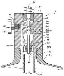
Figures 2 and 3 show specifically the valve structure indicated by reference
numeral
12. It comprises a main body 30, which is attached by a fitted threaded
connection
32 to a neck portion 34 at the upper part of container 10. The body 30 has a
central
longitudinal extending bore, having a varying dimension along its length. At
its
lower end 36, the bore is enlarged and receives the upper end of the tube 26,
conveniently provided with a threaded connection. The bore tapers inwardly to
form a valve seat 38 of a first valve. The bore enlarges, at 40, to form a
fluid
passage, described later in connection with Figure 4. Above the enlargement
40,
the bore decreases in size to form an elongate tubular seating at 42. Above
the
tubular seating 42, the bore is enlarged and a plug 44 is inserted to close
off the
bore, and also to form a chamber which serves as a transfer passage 46, again
described in more detail with respect to Figure 4. The plug 44 has a central
bore 48
and extending through the bore is an elongate valve member or stem 60. At its
lower end, the valve stem 60 has a tapered valve member or seal 62, which
cooperates with tapered valve seat 38. At an intermediate position, there is
provided
a second valve comprised of an extended valve portion 64 which cooperates with
the tubular seating 42.
The first valve comprised of valve member or seal 62 and valve seat 38 acts to
control flow of liquid from container. The second valve formed of the upper
end of
the valve portion 64 acts with the upper end of seating 42 to control flow of
gas from
the container 10.
A further bore 70 extends up through the body 30 and connects to a radial bore
72
extending to the central bore to form a port 76, between the enlargement 40
and the
passage 46. The outer end of the radial bore 72 is closed by a plug 78 which
can
CA 02368082 2001-10-30
WO 00/67850 PCT/CAOO/00520
-5-
be used to provide a connection to a pressure gauge. Considering the valve
portion
64, a reduced diameter portion 66 on the valve member 60 connects with the
passageway 46 only, in a closed position, as in Figure 2, and connects
passageway
46 with port 76, in an open position, as in Figure 3.
The upper end 80 of the valve member 60 extends beyond the plug 44. A lever 82
(see Figure 1) is pivotally mounted on the end of the stem 60 and extends over
the
outer end 80. A compression spring 81 is mounted on the outer end 80 of the
valve
member 60 to bias the valve member to a closed position. Pressure by the lever
82
on the outer end 80 of the valve member 60 will open both valves
simultaneously.
Various seals are provided for the valve member 60. An 0-ring 84 is provided
between the passage 46 and the upper end surface of the body 30, in the
example
of the plug 44, to prevent leakage from the top end or upper surface of the
body 30.
0-rings 86 and 88 are spaced apart to prevent leakage from port 76 to the
passage
46 and enlargement 40 in the valve closed position, and to prevent leakage
from the
port 76 to the enlargement 40 in the valve open position. 0-rings 100 and 107
can
be provided in a conventional manner, such as to seal threaded connections 32
and
the threaded connection between the plug 44 and the upper end of the body 30.
Figure 4 illustrates the attachment of the flexible hose 14 to the valve body
30, with
connections to the enlargement 40, and also connection of a flexible tube 110,
inside the hose 14 to the passage 46. The hose 14 is connected to the body 30
via
a threaded connection 112 in a bore 114 connecting to the enlargement 40. The
tube 110 extends up through a bore 116 in the top part of the body 30 to
connect to
the passage 46. As seen in Figure 1, the tube 110 extends through the hose 14
and
wand 16 to a nozzle assembly 18.
When the valves are closed, neither the liquid nor gas can flow from the
container
to the nozzle assembly 18. Pushing down on the lever 82 opens the valves to a
position as seen in Figure 3. Liquid escapes up past the lower end of the
valve
member 60 into the enlargement 40 and up through bore 114 and connection 112
CA 02368082 2001-10-30
WO 00/67850 PCT/CA00/00520
-6-
into the hose 14. Simultaneously, air escapes through bores 70 and 76, recess
66,
passage 46 and then through the tube 110 to nozzle 18.
One form of nozzle assembly 18 is illustrated in Figure 5. This assembly has a
nozzle member 120 attached to the end of the wand 16 and an internal
intermediate
support member 122 to which the tube 110 is connected. The member 122 includes
an orifice or bore 128 formed internally of the member 122, and can be, e.g.,
0.75-
1.5 mm in diameter.
The member 122 is connected to the nozzle member 120 forming an axial hollow
or
mixing chamber 126. A passage 124 provides access, via a port 125, to a mixing
chamber 126 for the liquid in the wand 16. Port 125, can be, e.g., 2 - 3.5 mm
in
diameter. Liquid enters the mixing chamber 126 through the port 125 at right
angles
to the longitudinal axis of the nozzle 18. Gas flows through bore 128 of the
member
122 into the mixing chamber 126 and interreacts with the liquid, for effective
atomization of the liquid.
The nozzle member 120 is circular in cross section, and has a closed end with
a
number of orifices 132. One arrangement is seen in Figure 6. The nozzle member
120, at one end of the nozzle assembly 18 has, when seen in cross section
(Figure
5) with respect to the longitudinal axis, an angled face 130, the angle being
preferably in the range of 60 to 75 .
The gas enters the mixing chamber in a longitudinal direction and combines
with the
jet of liquid that is entering the mixing chamber at port 125. Thus, this will
produce a
gas/liquid mixture. The mixture exits the chamber 126 through the orifices
132,
resulting in further expansion and further atomization of the liquid. The
orifice
pattern 132 combined with the amount of atomization and end face angles
produces
the described mist pattern.
To charge the container 10, about 6L of liquid, for example water is placed in
the
CA 02368082 2001-10-30
WO 00/67850 PCT/CAOO/00520
-7-
container. The gas, for example air, is fed into the upper part of the
container 10
through the wand 16 by removing the nozzle 120 and replacing it with an air
valve
(not shown). The gas source means is connected to the air valve, the valves
are
opened and air is fed into the container 10. After pressurization, the nozzle
is
replaced. Pressurization in this manner minimizes later tampering. As an
alternative, the gas is fed through bore 72 by removing plug 78. As a further
alternative, a pressure gauge can be permanently mounted at the bore 72, and
this
can be provided with a T-shaped valved connection having an air valve for
connection of a pressurized source of gas. The gas is generally pressurized
initially
to a maximum pressure of about 175 pounds per square inch.
Figure 7 illustrates an alternate embodiment of the valve structure 12. The
central
longitudinal extending bore above enlargement 40 is not enlarged, eliminating
the
need for a plug such as plug 44 (see Figure 4) to close off the bore. The bore
116
extends through the top of the valve body 30. The top of the bore 116 is
closed by a
plug 31. A second bore 33 serves as a transfer passage in place of the chamber
46
(see Figure 4), and is closed by plug 37. The valve structure 12 is otherwise
the
same as the_previous embodiment including the tube 110 which extends up
through
bore 116.
Figure 8 illustrates a further alternative embodiment of the valve structure
12. The
central longitudinal extending bore above enlargement 40 is not enlarged
eliminating the need for a plug such as plug 44 (see Figure 4) to close off
the bore.
Also eliminated is bore 116 (see Figure 7). A bore 33 serves as a transfer
passage
in place of the transfer passage or chamber 46 (see Figure 4), and is
connected
through a connection 112A to a flexible hose 14A. As with previous embodiments
of
the present invention, when the valves are closed, neither the liquid nor gas
can
flow from the container 10. In use, with similar components described above,
pushing down on a lever opens the valves whereby liquid escapes up past the
lower
end of the valve member into the enlargement and up through the connection and
into the hose. Simultaneously, air escapes through suitable bores or the like,
CA 02368082 2001-10-30
WO 00/67850 PCT/CAOO/00520
-8-
through a transfer passage and then through the connection 11 2A to the hose
14A.
A carrying handle can be attached through the valve structure 12 as seen in
Figure
1. The container is shaped so that such can normally stand upright on a
surface.
Although embodiments of the invention have been described above, it is not
limited
thereto and it will be apparent to those skilled in the art that numerous
modifications
form part of the present invention insofar as they do not depart from the
spirit,
nature and scope of the claimed and described invention.